GeneralComments Off on Restored Missing Files in the “PC Software” Section
May012024
The files in the “PC Software” section of JAMMArcade.net had been lost in a WordPress hiccup some time ago. Thanks to augitesoul sharing his backup of the files with me, they have now been restored.
This tutorial is a straightforward procedure for using a colorimeter to calibrate an arcade cab or consumer CRT. Using a colorimeter is perfect for people that want their displays calibrated to a high standard with no “eyeballing it” or guesswork involved.
Display color calibration in a nutshell is precisely matching the contrast, brightness and colors of a video display against a reference standard such that (A) the calibrated display looks the same as other calibrated displays and (B) subtle details in video games aren’t missed due to either color washout (white point too high) or black crush (black point too low).
Up front, here’s some vocabulary words that this tutorial uses:
White Point: The measurement of the brightest white your monitor can display.
Black Point: The measurement of the darkest shadow your monitor can display.
Contrast: Adjusts the White Point of the RGB color guns equally.
Brightness: Adjusts the Black Point of the RGB color guns equally.
Gain or Drive: Individually adjusts the White Point of each Red, Blue and Green color gun.
Cutoff or Bias: Individually adjusts the Black Point of each Red, Blue and Green color gun.
Color Temperature: Expressed in kelvins, color temperature is a parameter comparing the color of a light source (ie your display or a light bulb) against an real-world reference light source (ie the sun). Lower color temperatures (< 3000 K) are considered “warm” (red or yellowish) while higher color temperatures (> 5000 K) are considered “cold” (blueish).
The abbreviation for 6500 kelvin color temperature is D65 while the abbreviation for 9300 kelvin is D93.
Note that display color calibration is a VERY deep rabbit hole with a lot of information, detail and nuance. This guide is intended for enthusiasts that just want a procedure they can quickly step through to make their displays look nice. There’s much more you can do in addition to what I’ve written up here if you want to be very precise with your display’s calibration.
If you want to delve deeper into the world of color calibration, consider these resources and articles:
This tutorial steps you through a white point balance procedure for your display, but does not cover adjustment of the RGB primary and secondaries since adjustments to those are very specific to each CRT model. Geometry adjustment is also not covered here.
Necessary Calibration Components
Laptop or desktop Windows computer to run the Colorimeter
Colorimeter to accurately read color measurements off the display
Pattern Generator to push accurate calibration images to the display
Calibration Software that reads the values from the Colorimeter and displays them to you in a readable format
What I Use
X-Rite I1 Display Pro colorimeter – it’s around $30 – $100 used from Ebay.
PGenerator is a great pattern generation option since it supports 15 khz output for CRTs and the laptop you’re using to read measurements can control it automatically, but it is tricky to setup for the first time. There is an excellent YouTube tutorial by StickFreaks available here: https://youtu.be/D6z0wS5oRoE
HCFR – the same program that interfaces with the colorimeter – if the display you’re calibrating supports an output resolution that your HCFR PC supports.
If applicable, use a color generator that matches what will be connected to your display the most often – ie, if you’ll be running a MISTer FPGA in an arcade cab, use a MiSTer as your color generator.
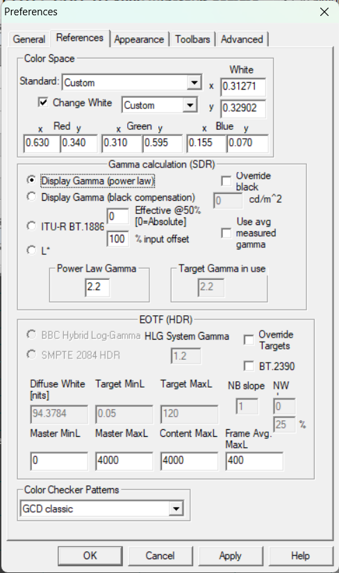
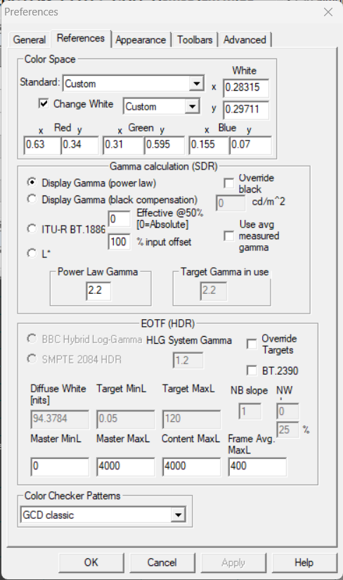
White Point Reference Selection
One decision you should make before you start is the white point standard you want your display calibrated against.
For retro video games, there are two target white point standards to consider:
D65 is considered the standard that US CRTs were calibrated for in the 80s-90s. It is a “warmer” white point and thus the display will have stronger red output.
D93 is considered the standard that Japanese televisions were calibrated for in the 80s-90s. Is is a “cooler” white point and thus the display will have a stronger blue output.
Choosing one or the other is a personal preference. Personally, I go with D65 for displays with US tubes (ie Zenith, RCA, Magnavox) and D93 for Japanese tubes (Sony, Toshiba, Panasonic, JVC, Hitachi)
IMPORTANT NOTE ABOUT TERMINOLOGY CRT manufacturers often confuse the labeling for Contrast, Brightness, Drive and Cutoff.
“Contrast” is the term for adjusting the White Point level.
“Brightness” and “Black Level” are two interchangeable terms for the Black Point adjustment. I use “Brightness” in this guide, but yours may be labeled “Black Level”.
“Drive” and “Gain” are two interchangeable names for the upper-end Red, Green and Blue color gun adjustments. I use “Drive” in this guide, but yours might be labeled Gain.
“Cutoff” and “Bias” are two interchangeable names for the low-end Red, Green and Blue color gun adjustments. I use “Cutoff” in this guide, but yours may be labeled Bias.
CRT and colorimeter setup 1) Connect your test pattern generator to the display.
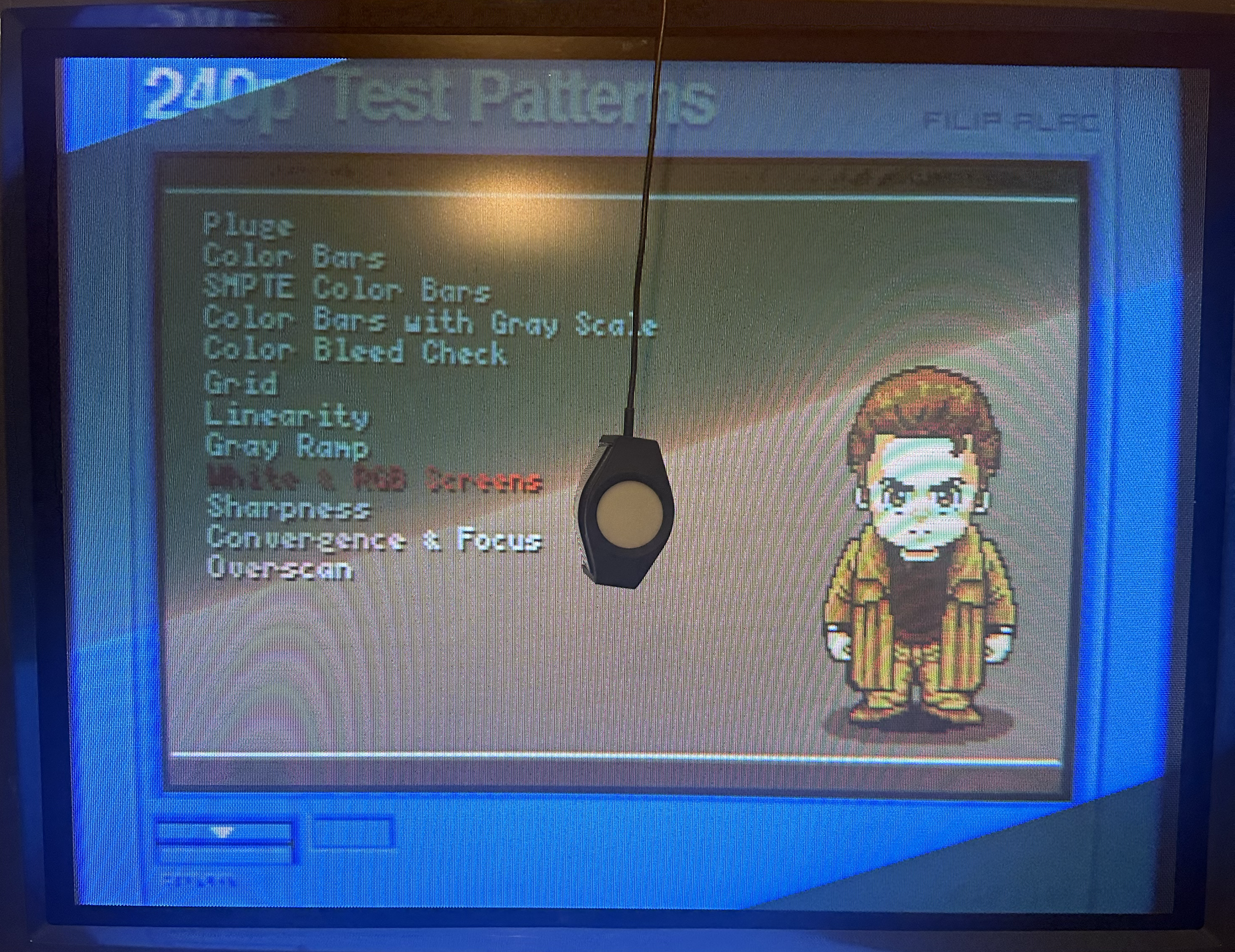
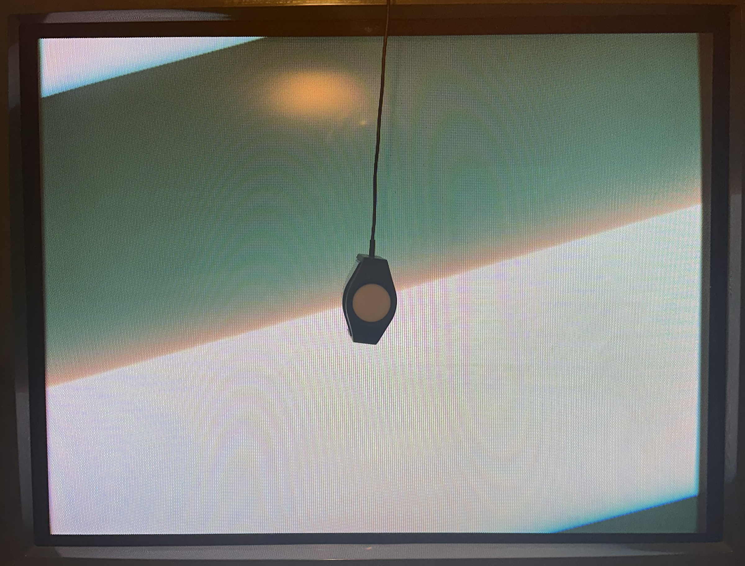
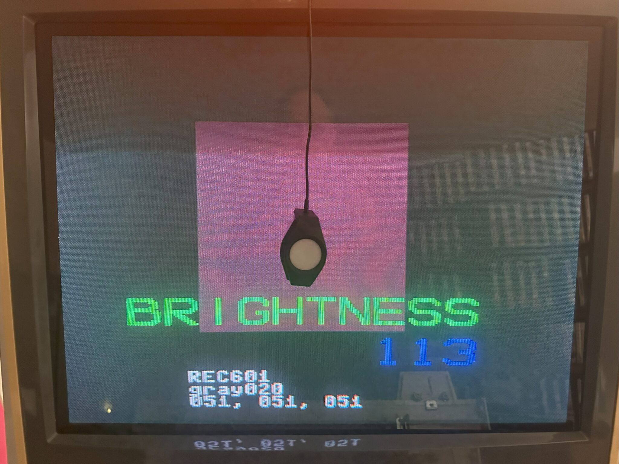
2) Power on the display. Display a 100% solid white test pattern. In the 240P Test Suite, go to “Test Patterns” -> “White Screen”.
3) Wipe down the monitor glass with glass cleaner. Place the colorimeter directly on the glass in the center of the screen. Place a book or something heavy on top of the cable to stop it from sliding or falling off the screen.
4) Wait one hour with the screen on all-white to let the CRT and chassis warm up.
5) Connect the colorimeter to your laptop running HCRF with the USB cable. Launch HCRF.
6) Click on the “File” menu and choose “New”.
7) On the Generator Selection screen, choose:
DVD manual: if you’re using a pattern generator that can’t be controlled from the laptop, such as MiSTer HCRF core, 240P Test Suite or a DVD Player.
Automatic: if the laptop is the pattern generator and thus connected to the cab display as a secondary monitor.
PGenerator will also be detected and used by HCFR when Automatic is selected.
8) Select your model of Colorimeter from the sensor list, select “Do not use a meter correction file” and click Finish.
9) Your meter might now ask what kind of display you’re calibrating – choose “CRT” or “Refresh Display”. Also, Reading Type should be set to “Display”. Click the Calibrate Meter button. Some meters will then ask you to display a white image of 80% IRE or higher. You’re already displaying a 100% IRE all-white screen, so just click OK to finish the calibration.
10) In the main HCFR window that appears, click on the Green Triangle button in the menu bar to start taking readings.
Adjustments – Ideally, you’ll want to do this with the room as dark as possible.
NOTE: If you don’t have straight-forward access to your CRT’s flyback, set each Drive, Cutoff, Contrast, and Brightness setting to the center position and move on to the next section.
1) Set the CRT controls as follows:
Each RGB Drive: All the way down.
Each RGB Cutoff: Center position.
Contrast: Center position.
Brightness: Center position.
2) Display a white grid pattern.
In the 240P Test Suite, go to “Test Patterns” -> “Grid”.
3) Turn the Screen dial on the flyback down (counter-clockwise) until the display is completely dark and pitch black. You want to go just past the last trace of the grid.
4) Turn each RGB Cutoff up until you see the black space around the white grid turn into the color you’re adjusting. Then turn it down until the black is perfectly black again.
5) Turn each RGB Drive up until the grid is really white without bleeding out / turning blurry.
Now the CRT is broadly dialed in, we can fine tune the adjustment using the colorimeter.
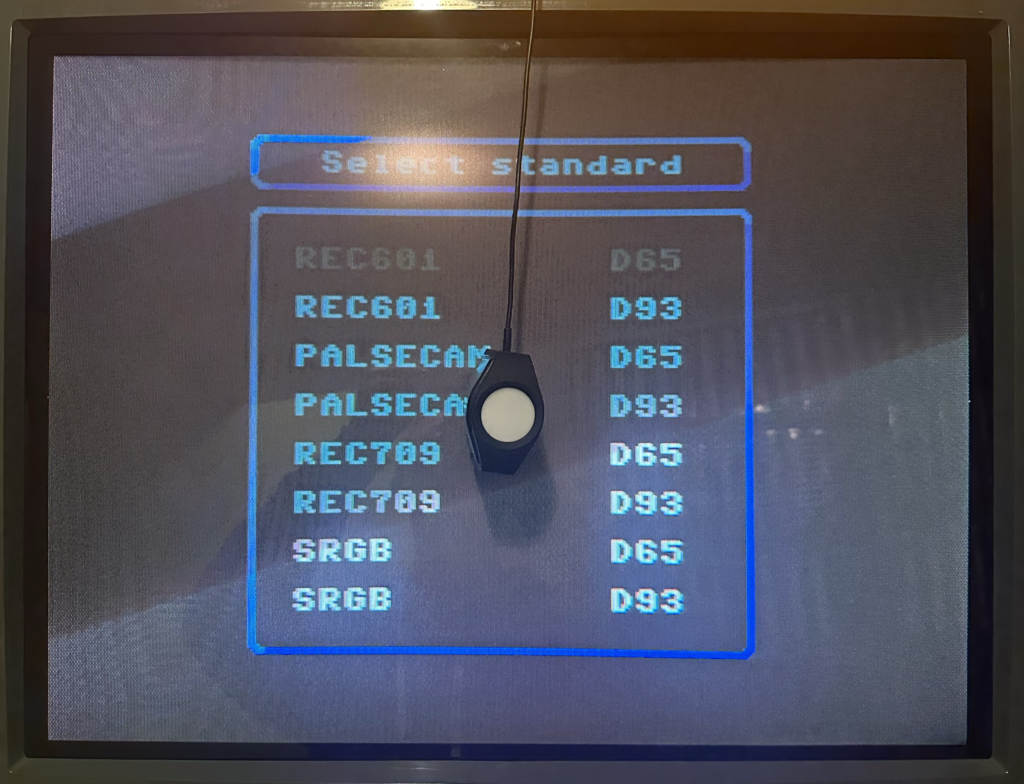
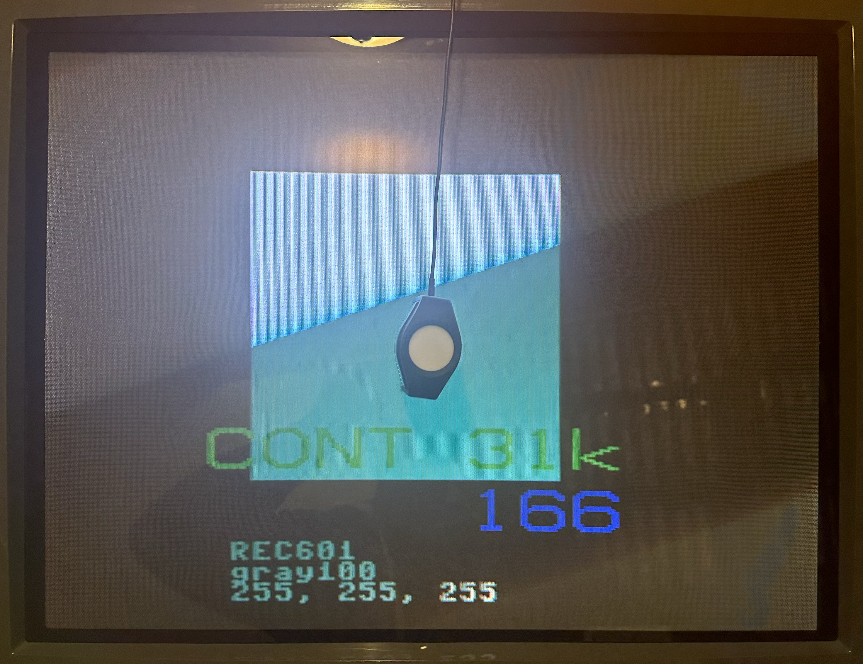
1) Display a 100% IRE test pattern. In the MiSTer HCFR core, choose “REC601 D65” or “REC601 D93” from the menu depending on which white point standard you’re using. Up and Down on the controller will cycle the IRE level up or down in 10% increments. In the 240P Test Suite, back out and go to “Test Patterns” -> “100 IRE”. Depending on the console, some control buttons will adjust the IRE level up or down in 10% increments.
2) Click on the 100 Column in HCRF. If the colorimeter isn’t currently taking readings, click on the green Triangle button in the upper-middle of the toolbar.
The “Y” measurement tells you how bright your screen is. Typically, you want it at 100 nits. If you plan to always run your display in a dark setting, you may want to go down to either 95 or 90.
Adjust the SubContrast dial (if you have one; Contrast otherwise) until the Y readout hits your target.
If your chassis doesn’t have any Contrast adjustment dials or if you can’t get the Contrast to go high enough to hit your target, try adjusting the Red, Green and Blue Drive/Gain pots evenly upward.
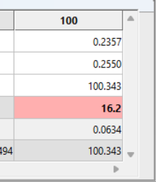
The Y Value reads 100.343 in this example.
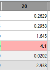
3) Click on the 20 Column in HCRF. Change your pattern generator to display a 20% IRE test pattern.
4) Your target now for the Y value is 0.3% of the reading at IRE 100. So if 100 nits is your IRE 100 target, 3.0 is what you want Y to read at IRE 20. HCRF also calculates the target value for you – look at “Y Target”.
Adjust the SubBrightness dial (if you have one; Brightness otherwise) until the Y readout hits your target.
The Y Value reads 1.645 in this example. The Y Target reads 2.938.
If you can’t go low or high enough try adjusting the Red, Green and Blue Cutoff pots evenly.
Note that aged chassis components and tubes may have trouble hitting these high and/or low targets. In that case, just get as close as you can.
5) When you change Brightness, it affects Contrast and vice-versa, so repeat Steps 2-4 until the Brightness and Contrast are balanced against each other with the appropriate Y target for each.
Drive and Cutoffs – Precise Calibration Part 2 1) Click on the 80 Column in HCRF. Change your pattern generator to display a 80% IRE test pattern.
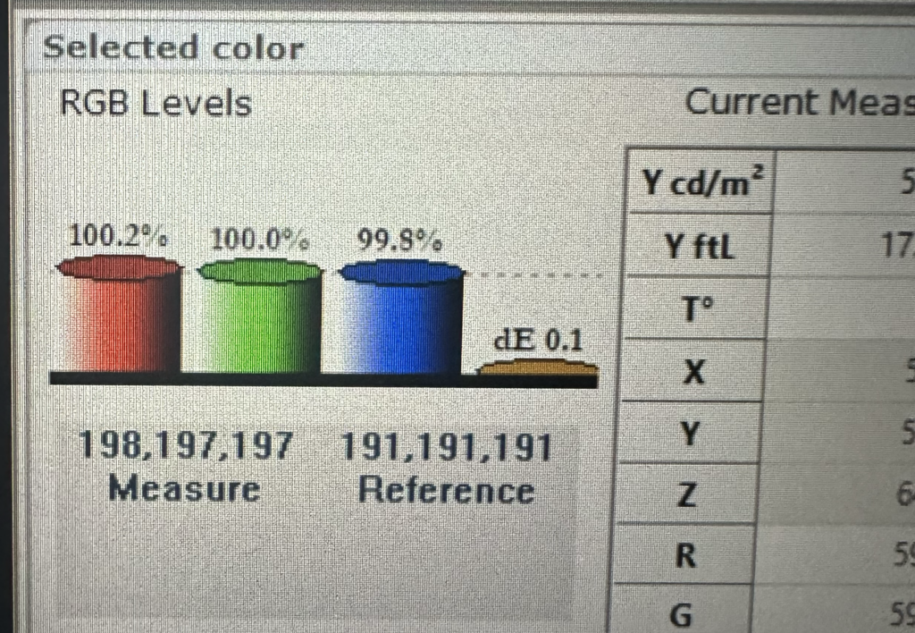
2) Look at the gauges in the lower-left corner of HCFR. The Red, Green and Blue gauges show your levels relative to the target, while the yellow gauge shows your Delta E (deviation) away from the target. As the RGB gauges get close to 100%, the Delta E gauge will drop. Your goal is to get Delta E as close to zero as possible.
Adjust the Blue and Red Drive pots until the gauges are as close to 100% as possible and Delta E is as close to 0 as possible. Adjust Blue first before Red.
Adjusting Green will scew both the Red and Blue levels, so you shouldn’t touch the Green pot unless you can’t get Red or Blue to adjust far enough to reach your targets. You’ll notice as you adjust the Red and Blue levels closer to 100%, the Green will be pulled there as well.
3) Click on the 20 Column in HCRF. Change your pattern generator to display a 20% IRE test pattern.
4) Adjust the Blue and Red Cutoff pots until the gauges are as close to 100% as possible. Adjust the Blue first before Red.
Adjusting Green will scew the Red and Blue levels, so you shouldn’t touch the Green pot unless you can’t get Red or Blue to adjust far enough to reach your targets. You’ll notice as you adjust the Red and Blue levels closer to 100%, the Green will be pulled there as well.
5) When you change the Drive pots, the Cutoff target shifts and vice-versa, so repeat Steps 1 – 4, going back and forth between 20 and 80 IRE and adjusting Cutoff and Drive respectively until both of them are as close to 100.0% RGB and 0.0 Delta E readings as possible on the gauges.
Now, the display is pretty well dialed in at this point, but if you’re extra picky, repeat the Part 1 – Contrast and Brightness steps one more time, because adjusting the Drive and Cutoffs will have shifted those values a little bit. If you do end up readjusting Contrast and Brightness, you’ll also have to readjust the Drive and Cutoffs again afterward as well, but none of them will need very much readjustment.
Verifying the White Balance Calibration If you’d like to check your cab CRT now and see how the White Balance calibration holds up across the gamma range, do the following:
1) In HCFR, click the Green Triangle to stop taking constant readings.
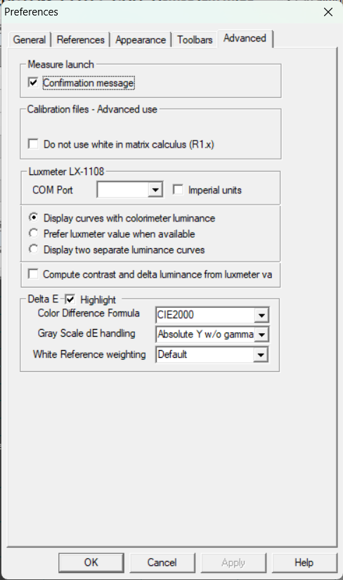
2) Click the Measures menu and choose “Gray scale”, and click Yes at the prompt.
3) The software will prompt you to “set 0% grey level”. Set an IRE 0% test pattern on your generator. In 240P Test Suite, use the L and R buttons on the controller to set IRE to 0, and click OK.
4) After a moment, the software will now prompt to “set 10% grey level”. Set an IRE 10% test pattern on your generator. In 240P Test Suite, use the L and R buttons to set IRE to 10, and click OK. Repeat all the way up through the 10 incrementing IRE levels.
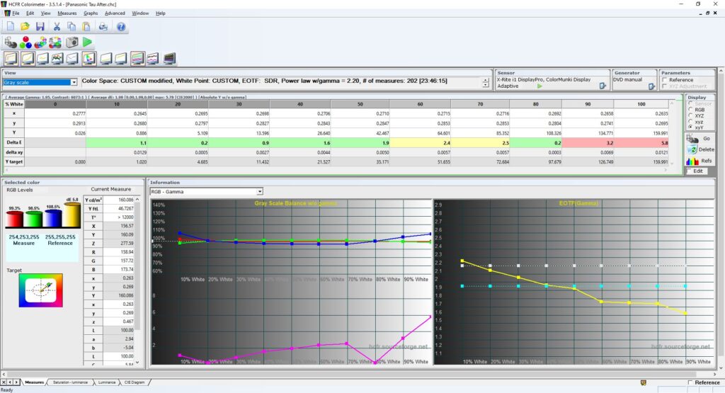
5) When the measurement is complete, look at the DeltaE row. Recall that DeltaE measures your variance from the perfect white balance target. If all ten cells are green (Delta E < 2.0) then you’re in good shape – your white balance is approximately on-par with a professional CRT. If some or all of the cells are yellow (Delta E between 2.0 and 3.0) then you’re approximately on par with a consumer CRT. If some or all of the cells are red (Delta E > 3.0) then you’re off target – either the calibration is wrong, your chassis PCB needs servicing, or the color guns in your tube are worn out.
Also, with Gray Scale selected from the drop-down in the upper-left corner, make a note of your Average Gamma and your Contrast Ratio. Ideally, you want an Average Gamma of 2.2 and an Average Contrast Ratio of at least 1000 : 1, but your results will vary based on tube and chassis age, specs, etc.
This post-calibration result of a Panasonic Tau consumer CRT shows some drift at the 90 and 100 IRE levels.
Note that calibration drifts as the tube and caps age – you may want to “tune up” your calibration every couple of years.
Post-Calibration Examples
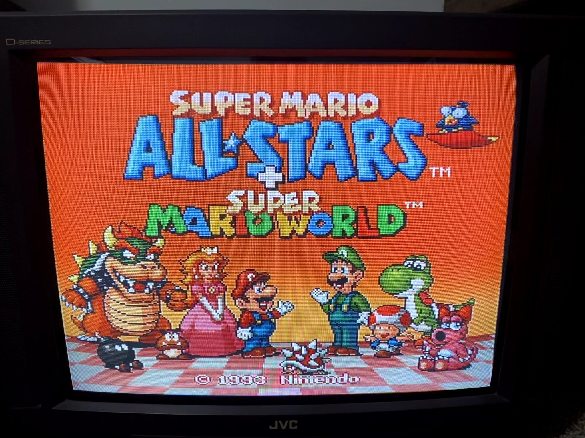
Sony GDM-FW900Nanao MS9Nanao MS9Mitsubishi DiamondTronJVC D-SeriesToshiba D29C051 This tube is worn and has burn-in and poor black levels
The Seibu Kaihatsu SPI platform was offered in two configurations:
Two Board – Main Board and cartridge ROM Board
Region locked: Main Board must match country of cartridge ROM Board. This protection can be bypassed – see “Protection Mechanisms” below.
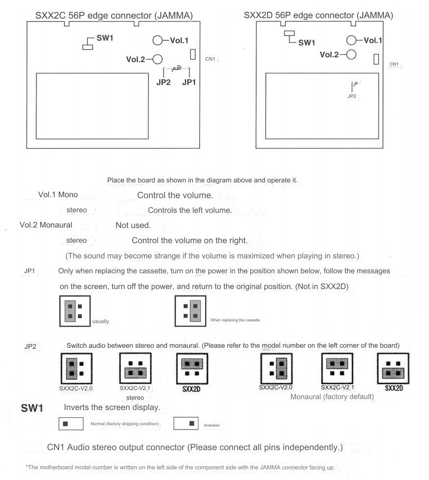
Optional Stereo audio.
Single Board
Only runs the one game that was loaded onto it at the factory.
Offered with two different audio setups- Yamaha YM-271-F or dual OKI MSM6295
Mono audio only.
This article will address the two configurations separately.
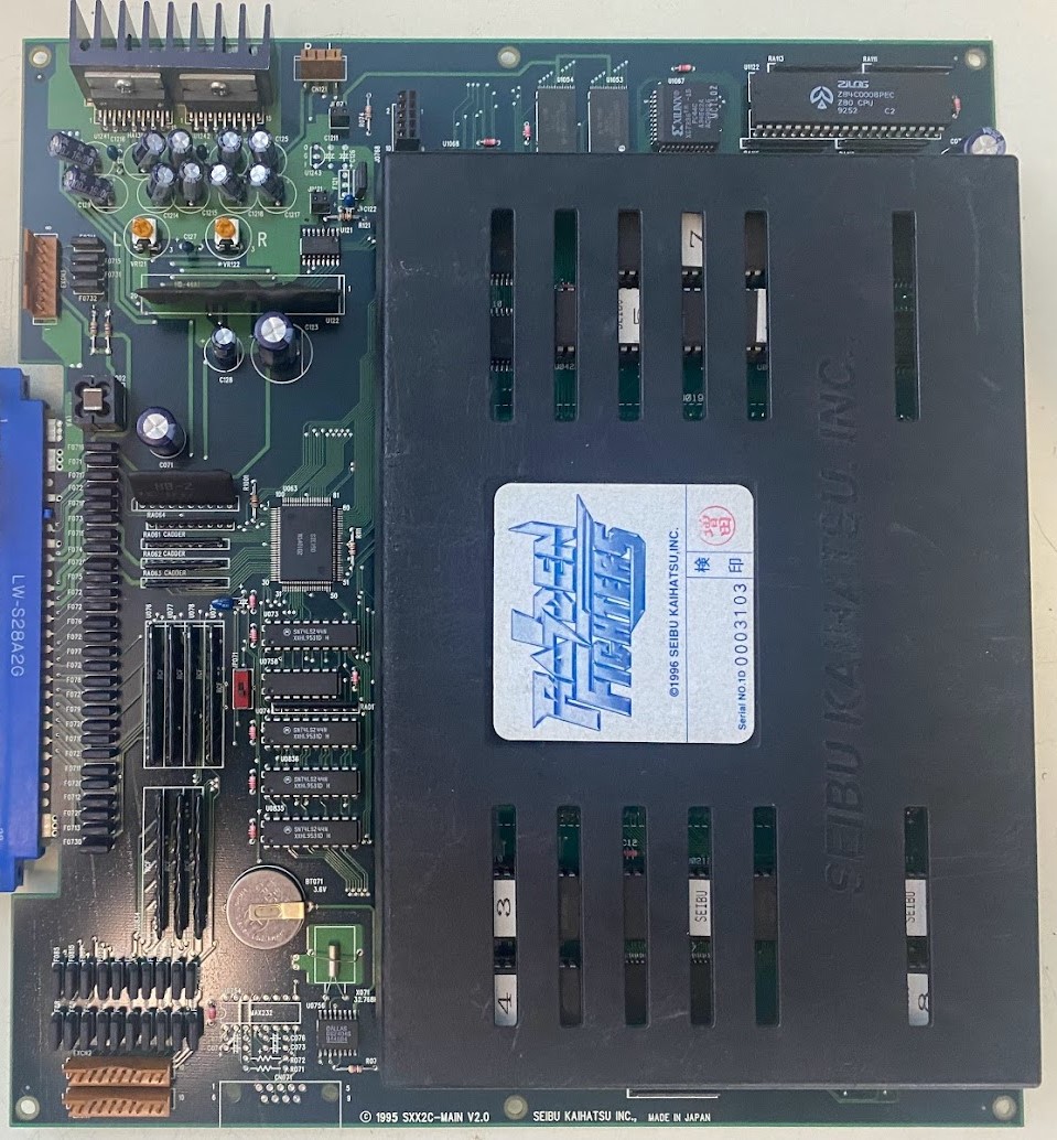
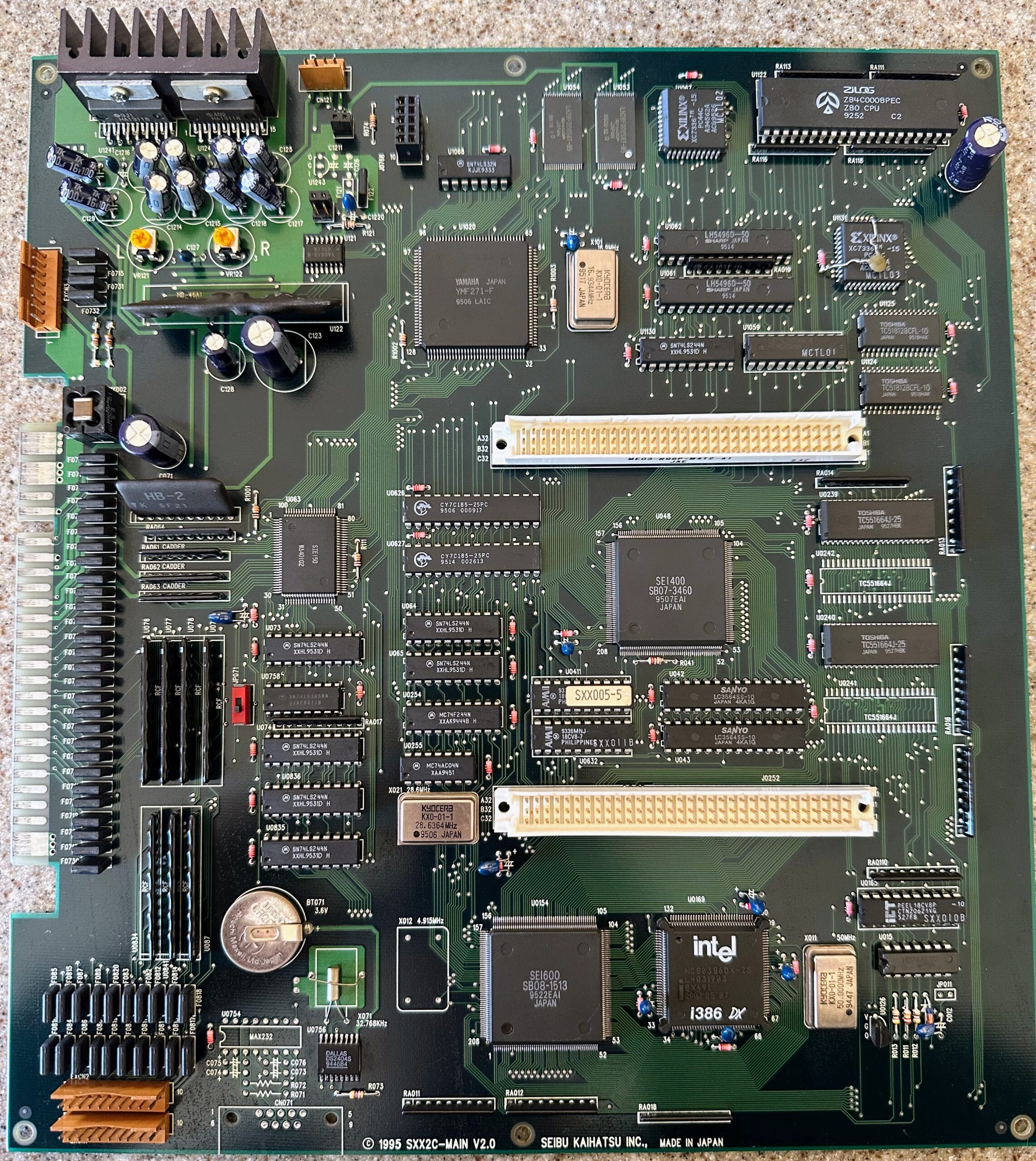
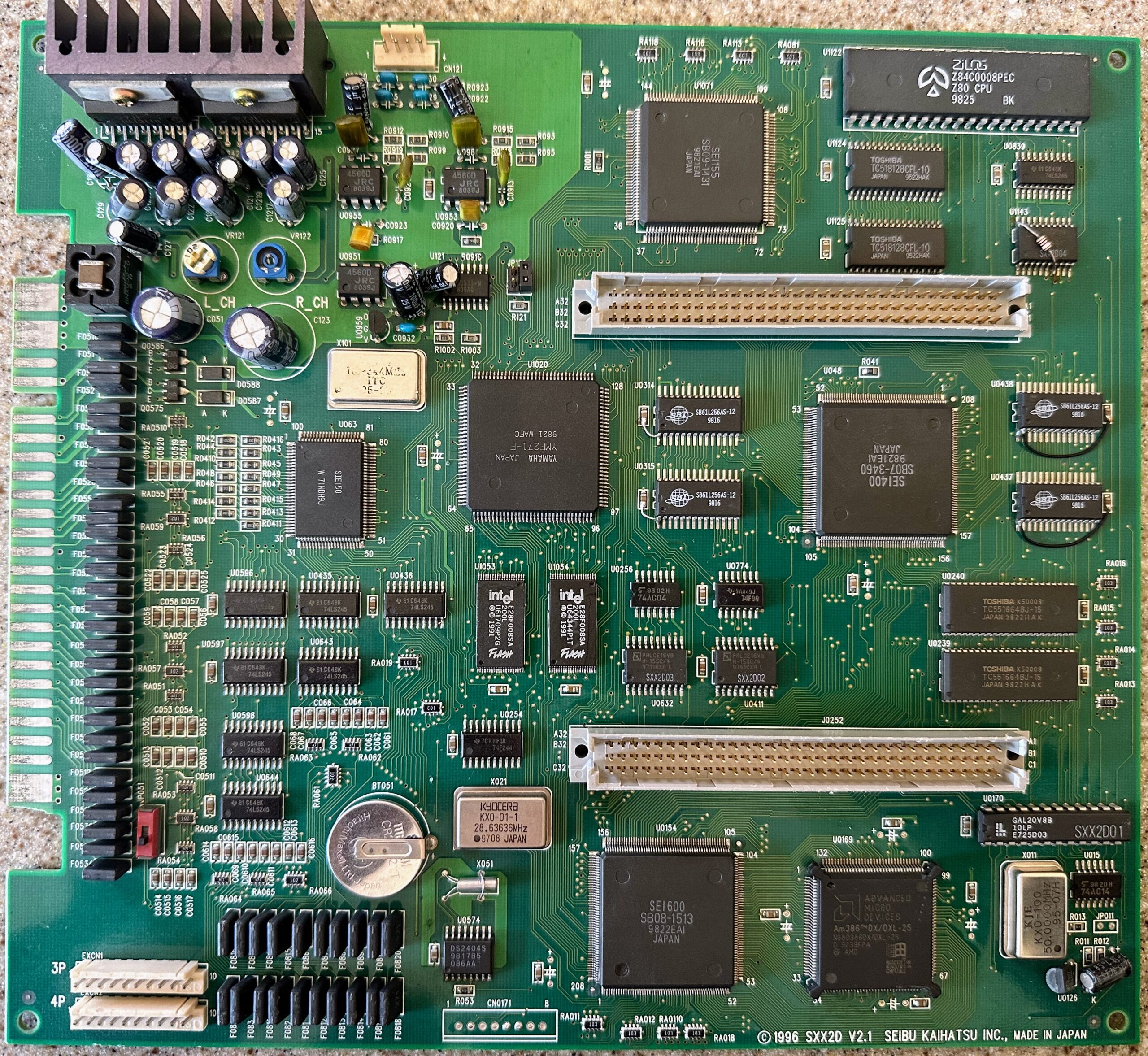
Two-Board Configuration: Main Board
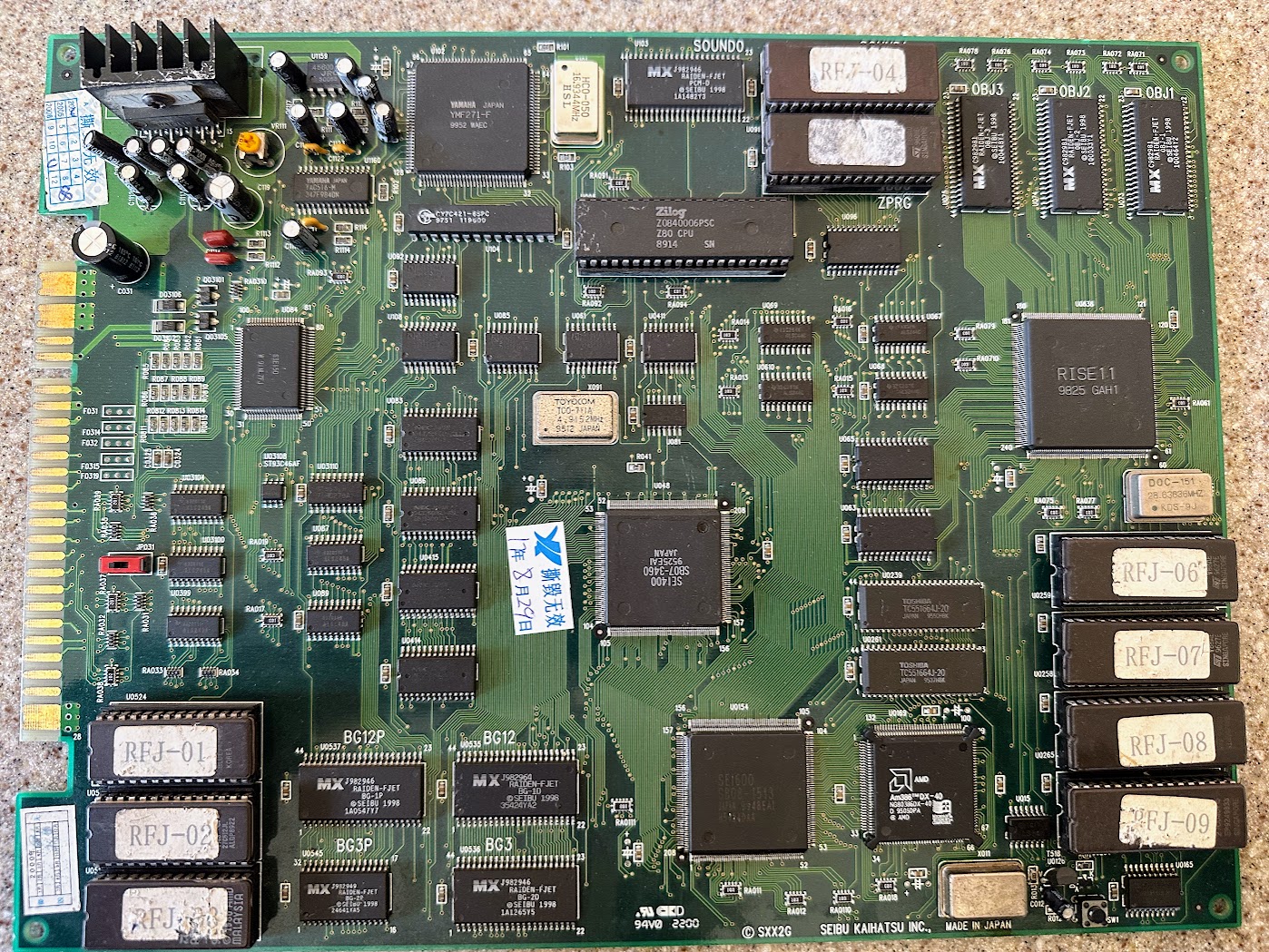
The SPI main board contains all the processing logic to run the game. It was released with two revisions, both of which can run the same ROM game cartridges. The marking on the board for each revision is:
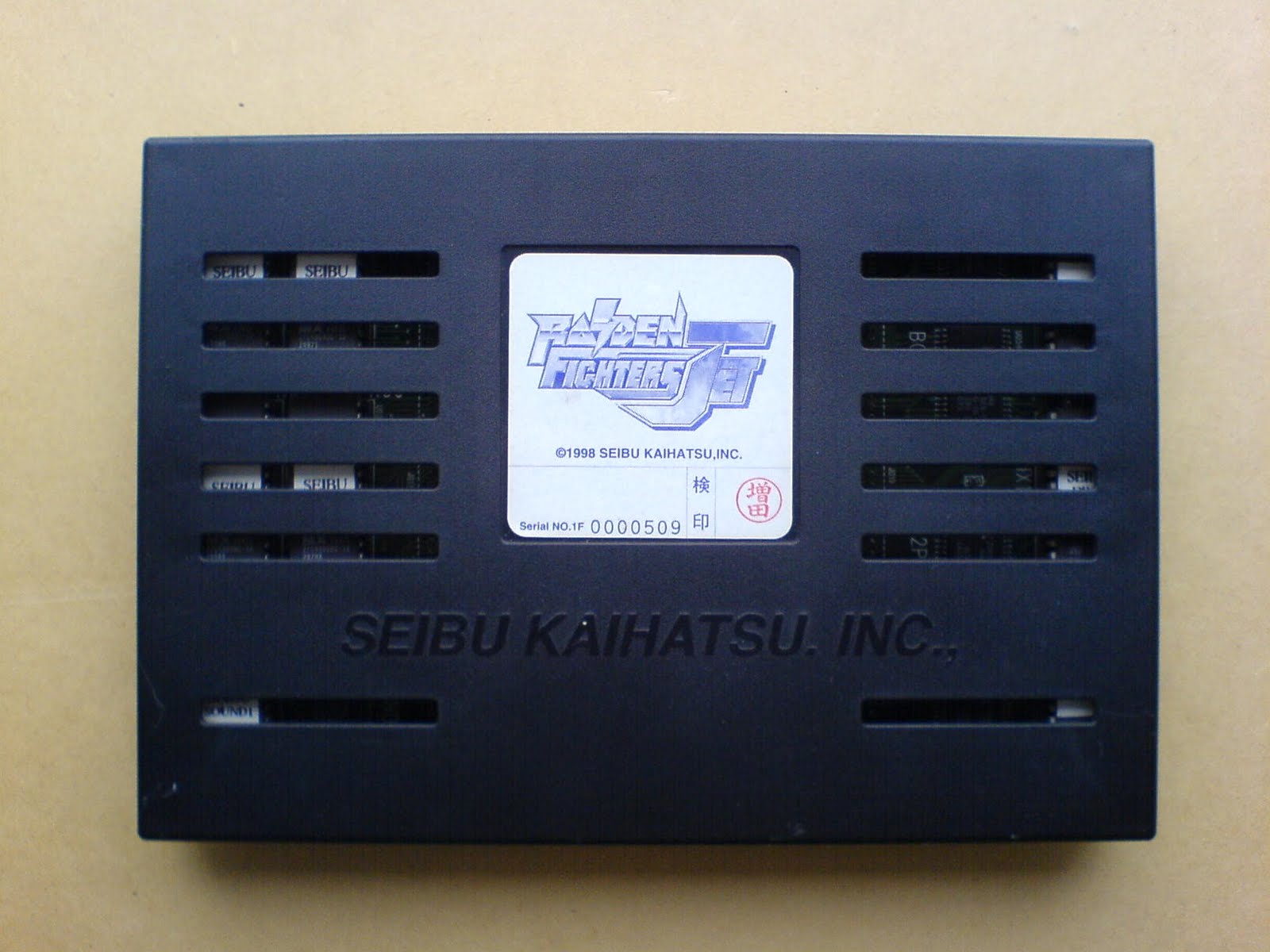
SPI Main Board V2.0 with Raiden Fighters cartridge Photo Credit: ShootTheCoreSPI Main Board – V2.0 Photo Credit: ShootTheCoreSPI Main Board – V2.1 Photo Credit: ShootTheCore
The SPI system has onboard flash memory used for both region lockout and to store part of the game. The V2.0 board restricts write access to the flash memory by a jumper labeled JP072. The V2.1 board does not have any flash write access restriction jumper.
When swapping game cartridges, you will need to change the jumper (V2.0 only), install the new cart, power on, wait for the game to write to the flash memory (the message “NOW UPDATING. PLEASE WAIT A MOMENT.” will be displayed), power down and flip the jumper back (V2.0 only). Even after flashing, the ROM cartridge must stay attached for the game to operate.
Notable ICs
IC
Function
PCB Label
AM386DX/DXL-25 – OR – Intel NG80386DX25
25.0 Mhz Main CPU
U0169
Zilog Z84C0008PEC
7.15909 Mhz Audio CPU
U1122
Yamaha YM271-F
Audio Processor and Flash Access
U1020
Yamaha YAC513-M
Audio DAC
U1068
Intel E28F008SA – OR – Sharp LH28F008
8 MBit FlashROM
U1053, U1054
SEI400
Graphics Rendering
U048
SEI600
Graphics Rendering
U0154
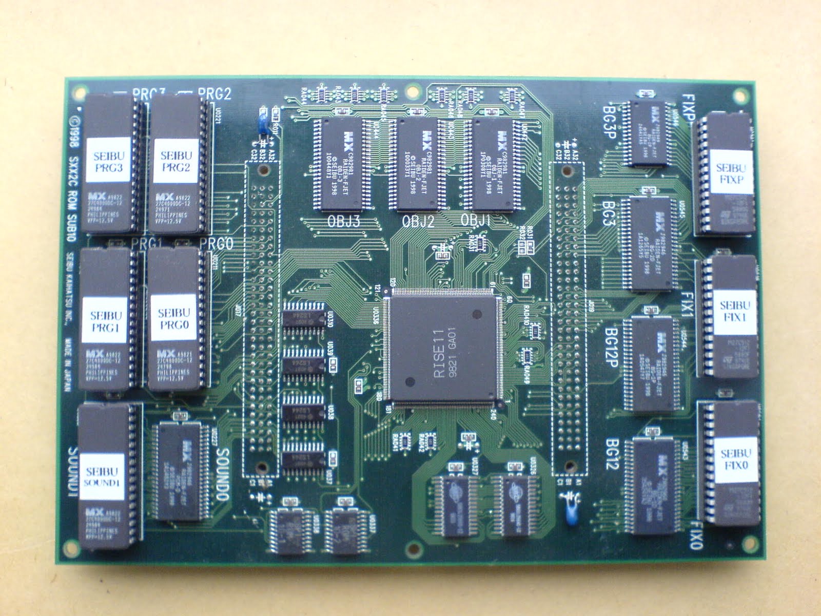
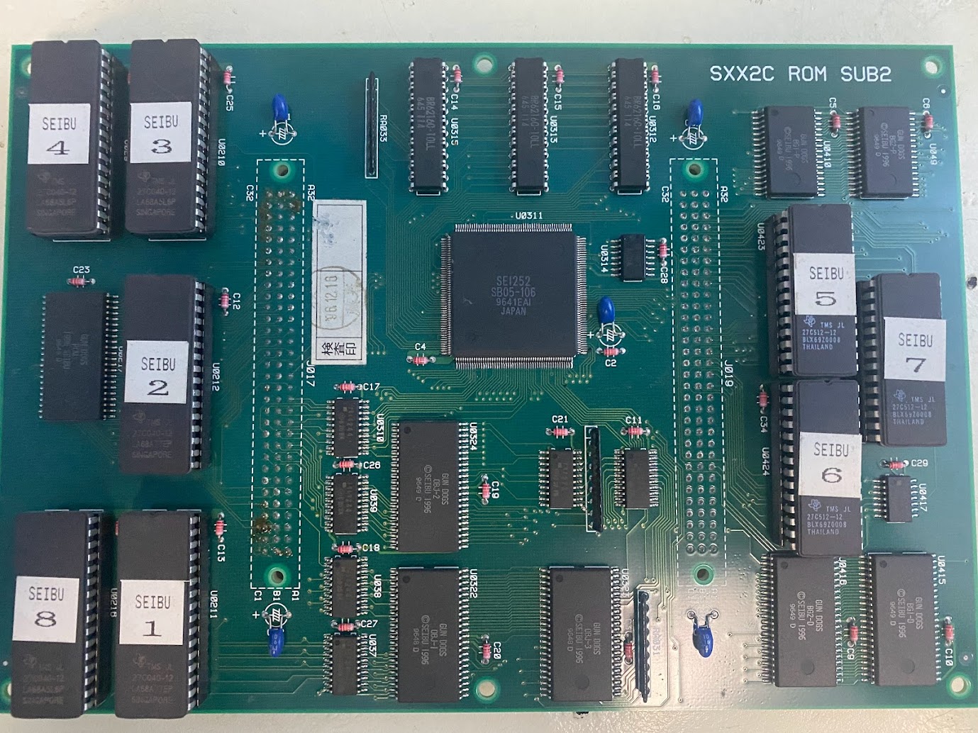
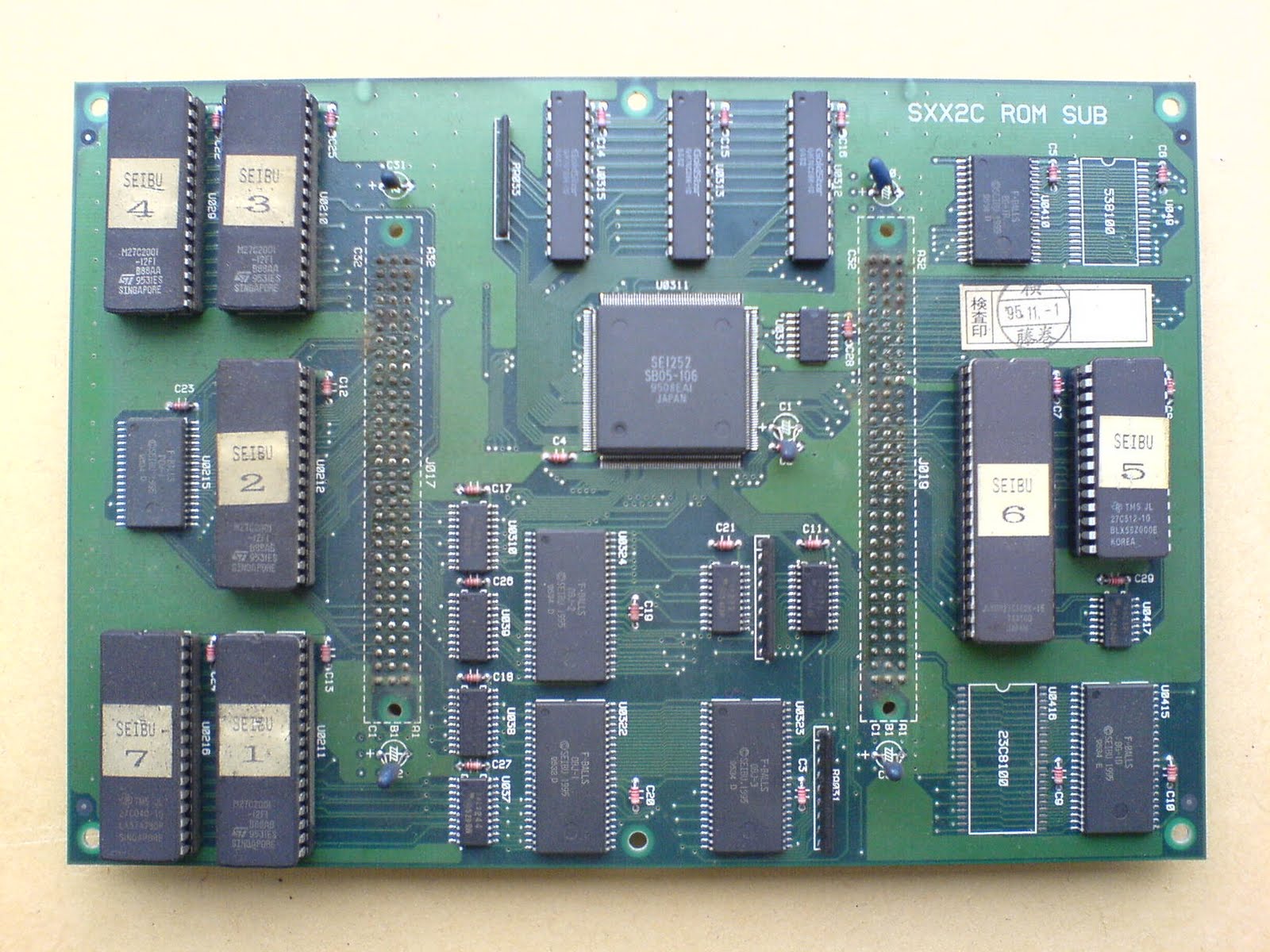
Two Board Configuration – ROM Cartridge Board
Cartridge boards include DIP socket EPROMs, SMD mask ROMs, SRAM and a custom decryption IC – see Protection Mechanisms below. It is not possible to reliably convert one SPI game cart to another at this time, although it is possible to upgrade the same game to a different version (ie Viper Phase One to Viper Phase One NV).
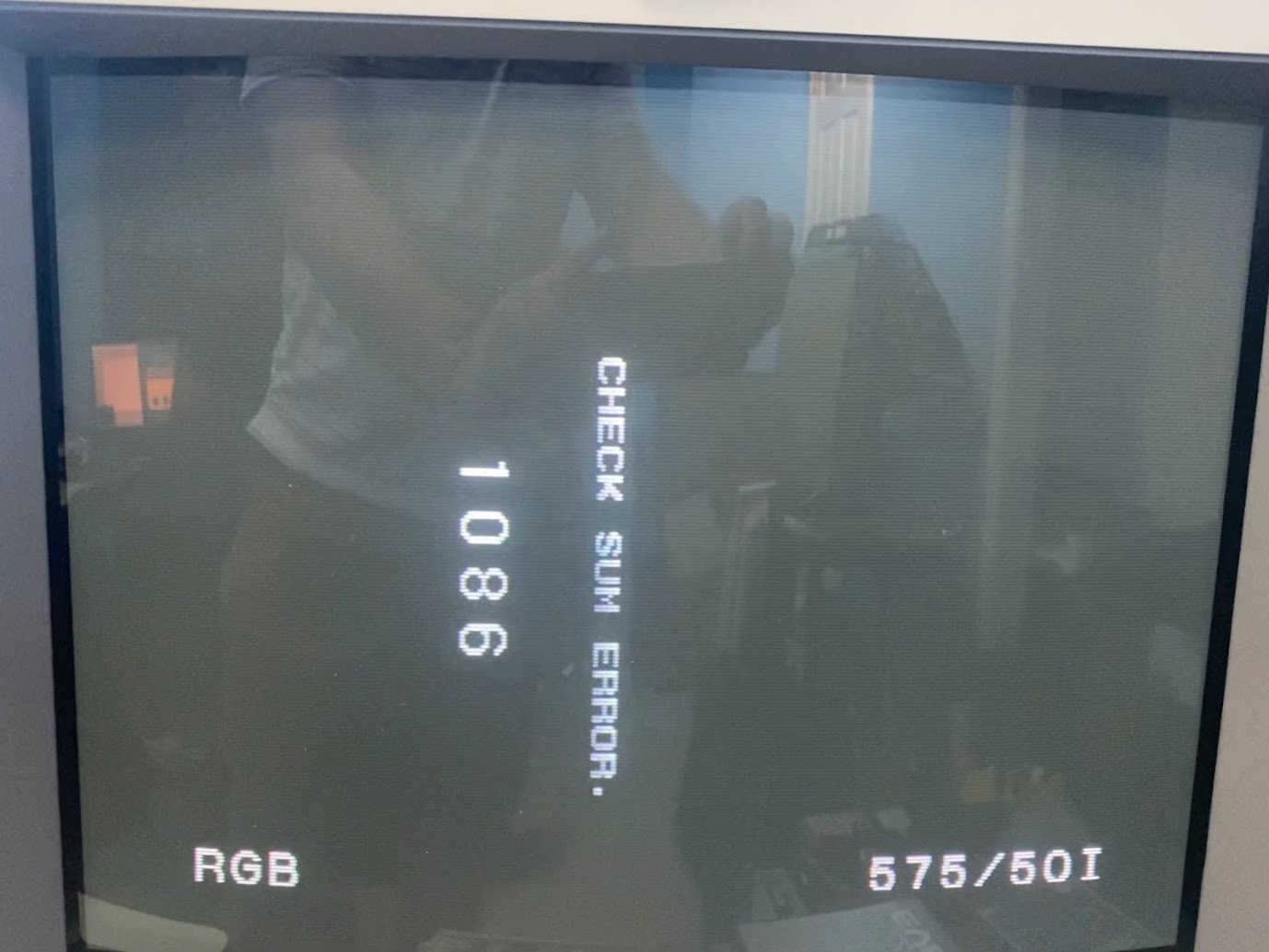
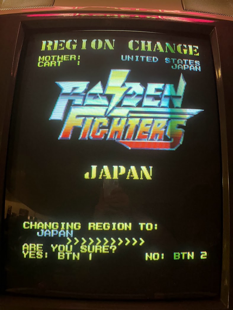
The two-board SPI platform stores part of the game inside onboard flash storage. The flash storage is also initialized from the factory with a country code. If the country code stored in the first byte of u1053 flash on the mainboard does not match the country code stored in the last byte of the PRG0 EPROM on the ROM cart then you will see the message CHECKSUM ERROR XXXX or HARDWARE ERROR XXXX during the flash process where XX is a two or four digit error code.
Raiden Fighters error during the flash process due to a mismatched region code. Photo Credit: ShootTheCoreSPI Revive changing the country region Photo Credit: ShootTheCore
It is possible to desolder the u1053 flash chip from the main board to reprogram it with a new code. A list of the country codes is in the opening comments of the MAME driver.
Alternatively, Trap15 developed a software solution named SPI Revive that can rewrite the country code on the mainboard by swapping the PRG0 EPROM on a Raiden Fighters or Raiden Fighters 2 cart. If SPI Revive is unable to change the country code then the u1053 flash chip should be replaced.
There have also been cases where the flash chips are holding the correct country code data but the board isn’t reading that data correctly. The Yamaha YM271-F sound chip controls access to the flash storage, so check the connections and traces on it.
Reflowing the solder on all of the large SMD ICs is recommended for HARDWARE ERROR and CHECKSUM ERROR messages if the earlier methods of writing the country code do not resolve the problem. Credit: ChannelManiac
Boot Failure or Vertical Lines (jailbars) through graphics(credit: twistedsymphony)
It is common for the large SMD ICs to have pins separate from the PCB due to board flexing.
If an SPI board fails to boot at all on a known-good ROM cartridge, try reflowing the solder on each SMD IC, starting with the 386 Main CPU – it seems particularly susceptible to this issue.
If an SPI board has vertical lines running through the graphics, reflow the solder on the two SEI400 and SEI600 graphics rendering ICs.
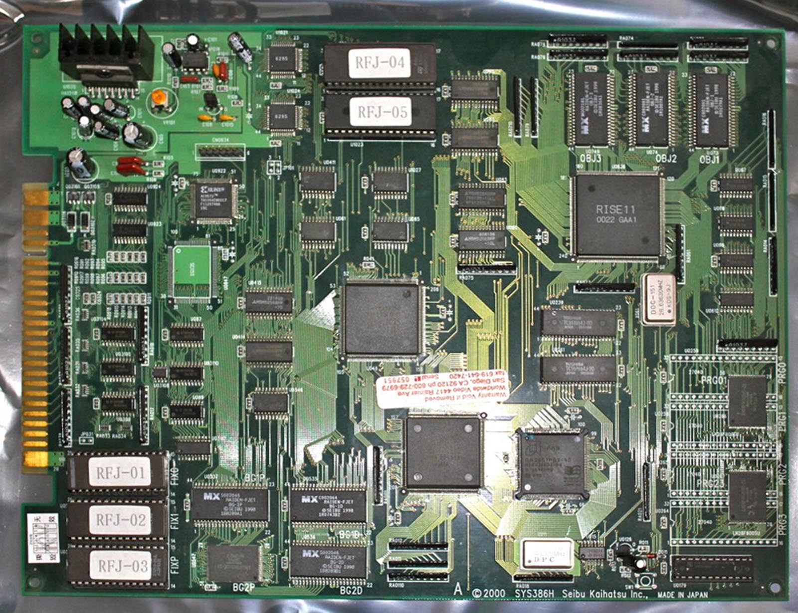
Single Board Variants
In some regions, Seibu Kaihatsu released some of their games on cost-reduced, all-in-one single boards. These boards are “locked” to the game they ship with, do not have stereo output available, and in some cases use lower-quality dual OKI MSM6295 ICs for audio instead of the Yamaha YM271-F IC that the two-board SPI platform utilized.
SYS386I -Raiden Fighters 2 Operation Hell Dive 2000 (AMD 386 CPU and dual OKI MSM6295 Audio)
SYS386F – E-Jan Sakurasou (Intel 386 CPU and Yamaha Audio)
SYS386H – Raiden Fighters Jet 2000 (AMD 386 CPU and dual OKI MSM6295 Audio)
SXX2F – E-Jan Sakurasou (Intel 386 CPU and Yamaha Audio)
SXX2G – Raiden Fighters Jet (AMD 386 CPU and Yamaha Audio)
Due to the variety of ROM boards used across the SPI games, consult the MAME Driver for game-specific ROM assignments.
The DIP EPROMs can be replaced with a 27C040 EPROM. Replacement of a faulty SMD Mask ROM with an SMD flash might be possible depending on which mask ROM it is.
Protection Mechanisms
Sprite data is encrypted differently for each game and paired to a specific sprite data decryption IC on the cartridge board. This proved to be an effective deterrent against cartridge game conversions and bootlegging.
Schematics& Datasheets
Schematics for the SPI hardware are not available.
Board is a bit dusty but very clean nonetheless. Some very specific chips are rusty, probably due to some rodent fluid. Tracks are invisible and located in the core of this 4-layer board making the inner tracks very fragile when pulling a chip out.
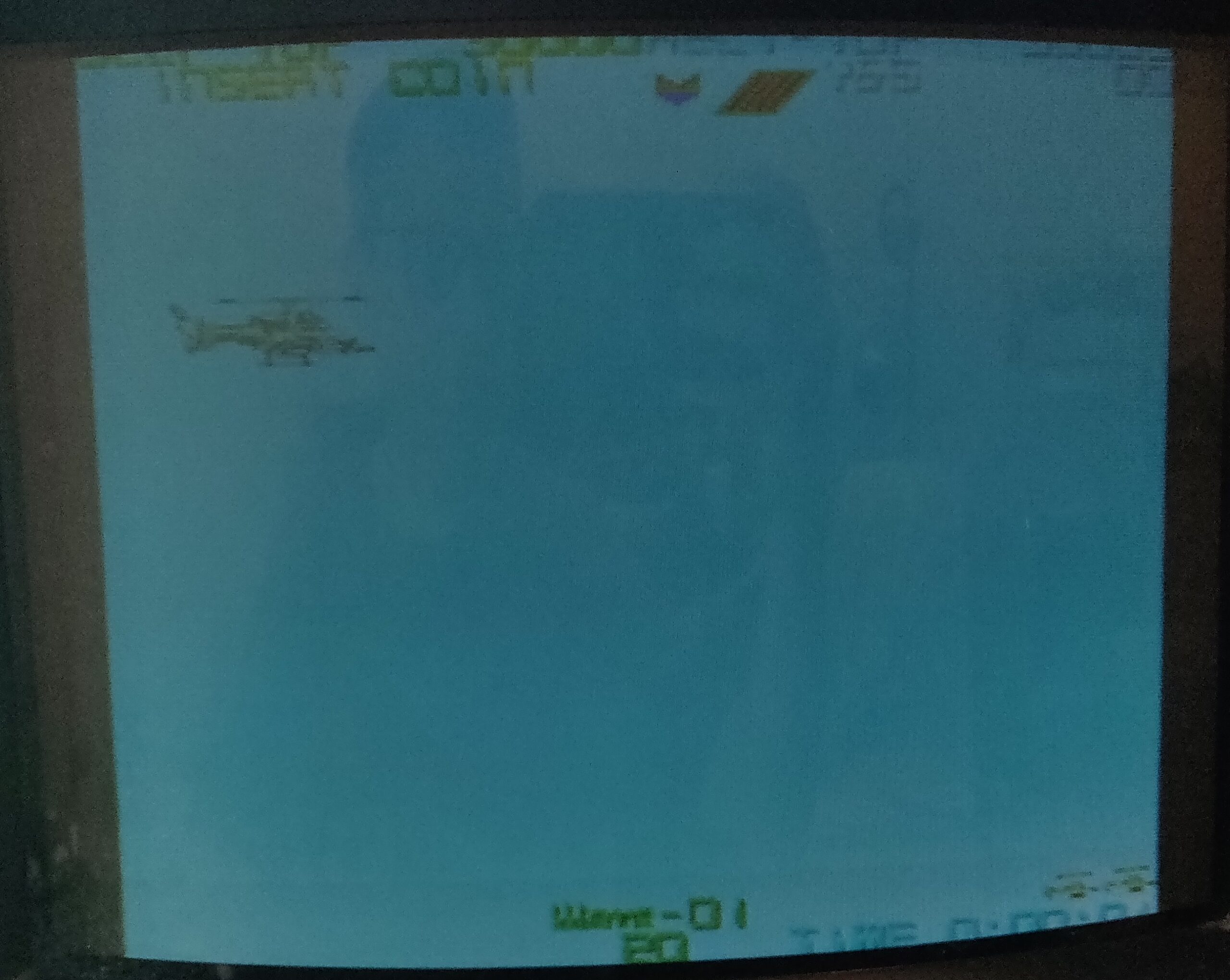
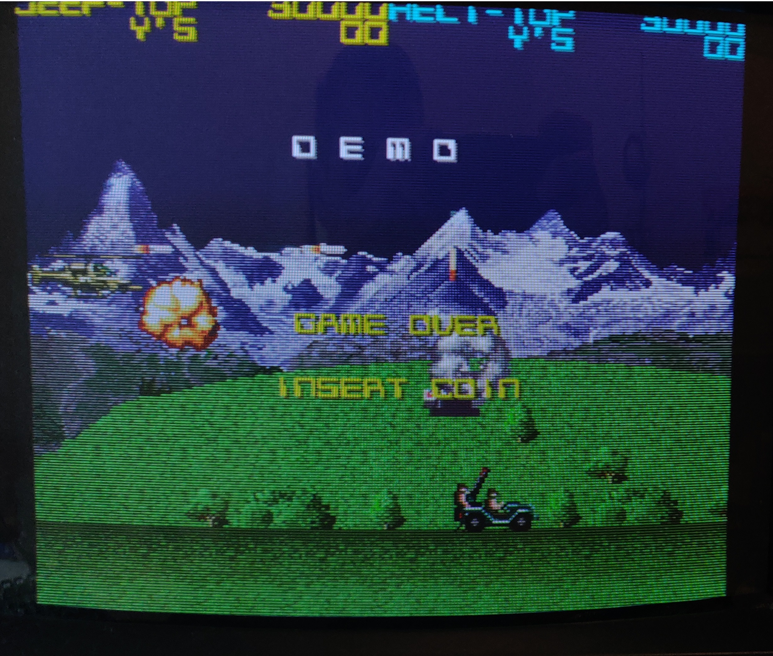
Game starts when powering the board with full sound and some graphics. The title screen has a white background instead of black as it should be. A similar white background appears during attract mode:
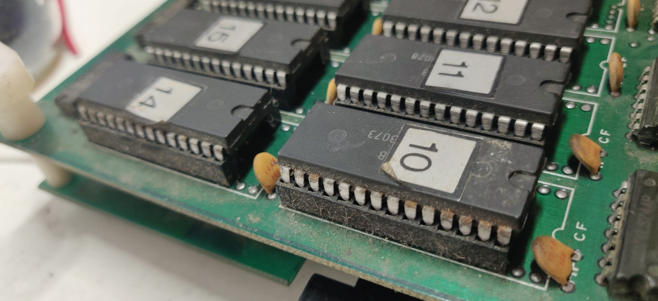
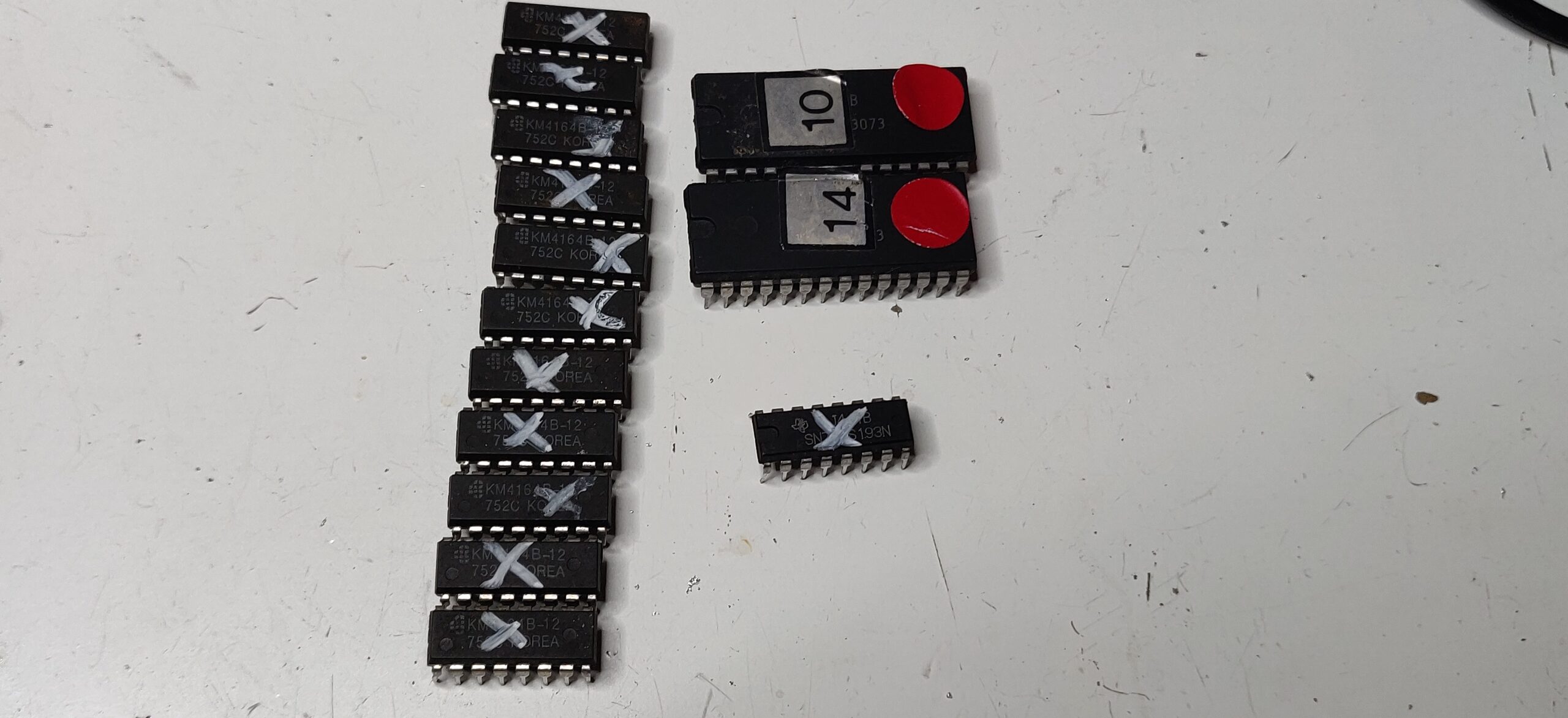
Cross-testing the board with a good one points the fault to the bottom board (graphics board). On this board I started probing the 8 EPROMs filled with the background graphics data. Some pins are quite corroded, so I decided to dump them to check their contents against MAME data:
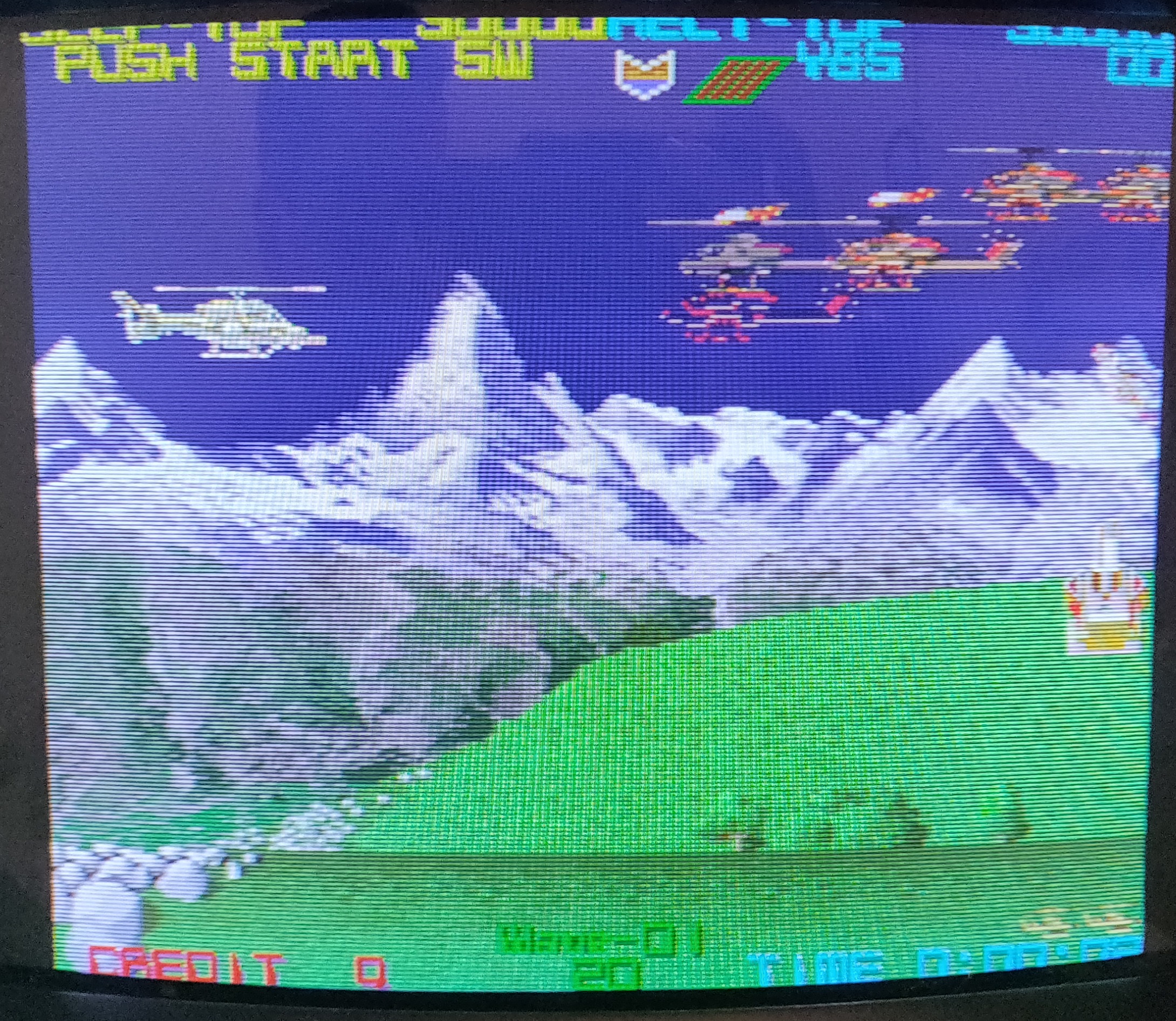
As a result, EPROMs 10 and 14 are dead. I burnt two replacement EPROMs and that brought the background back:
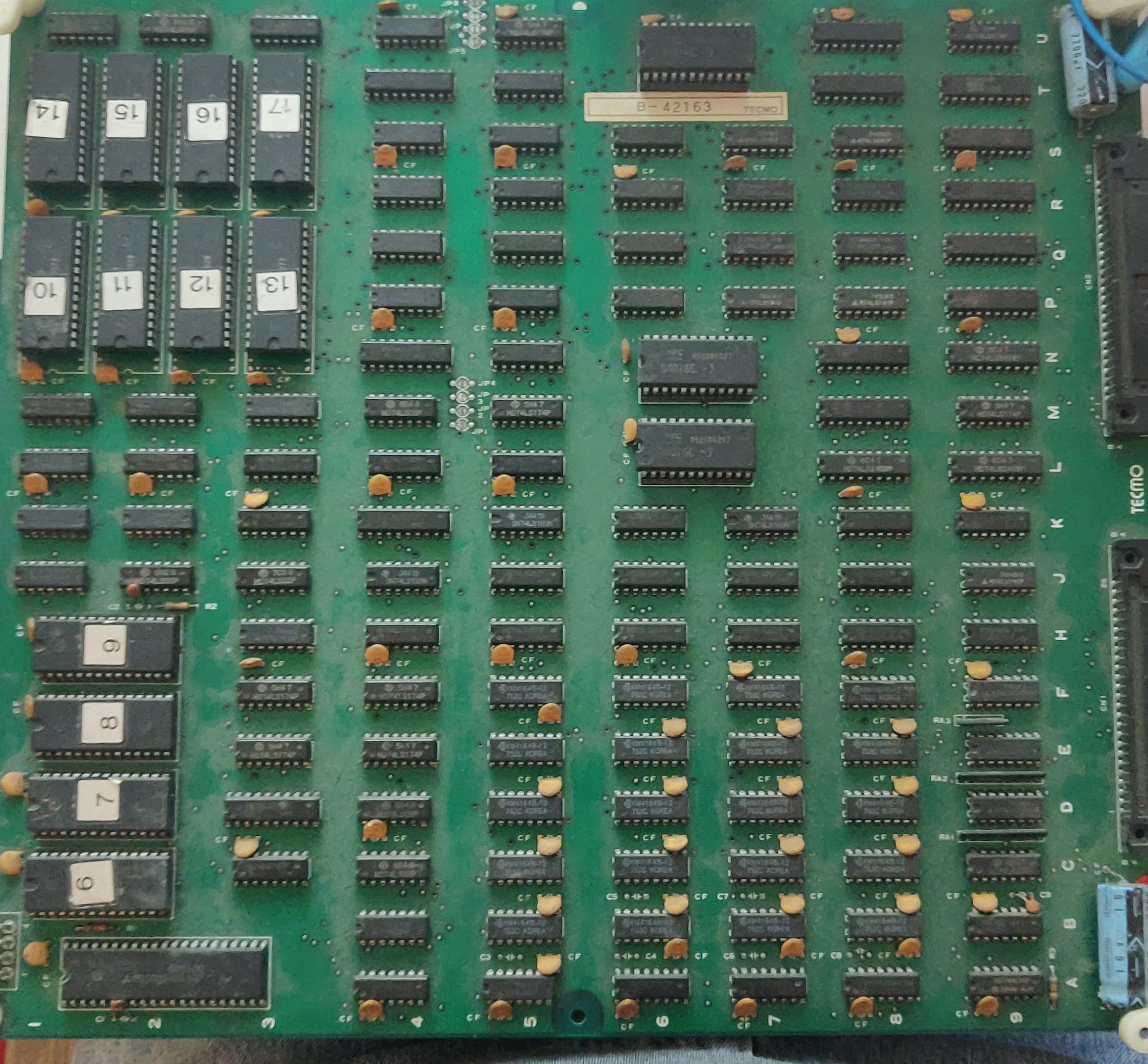
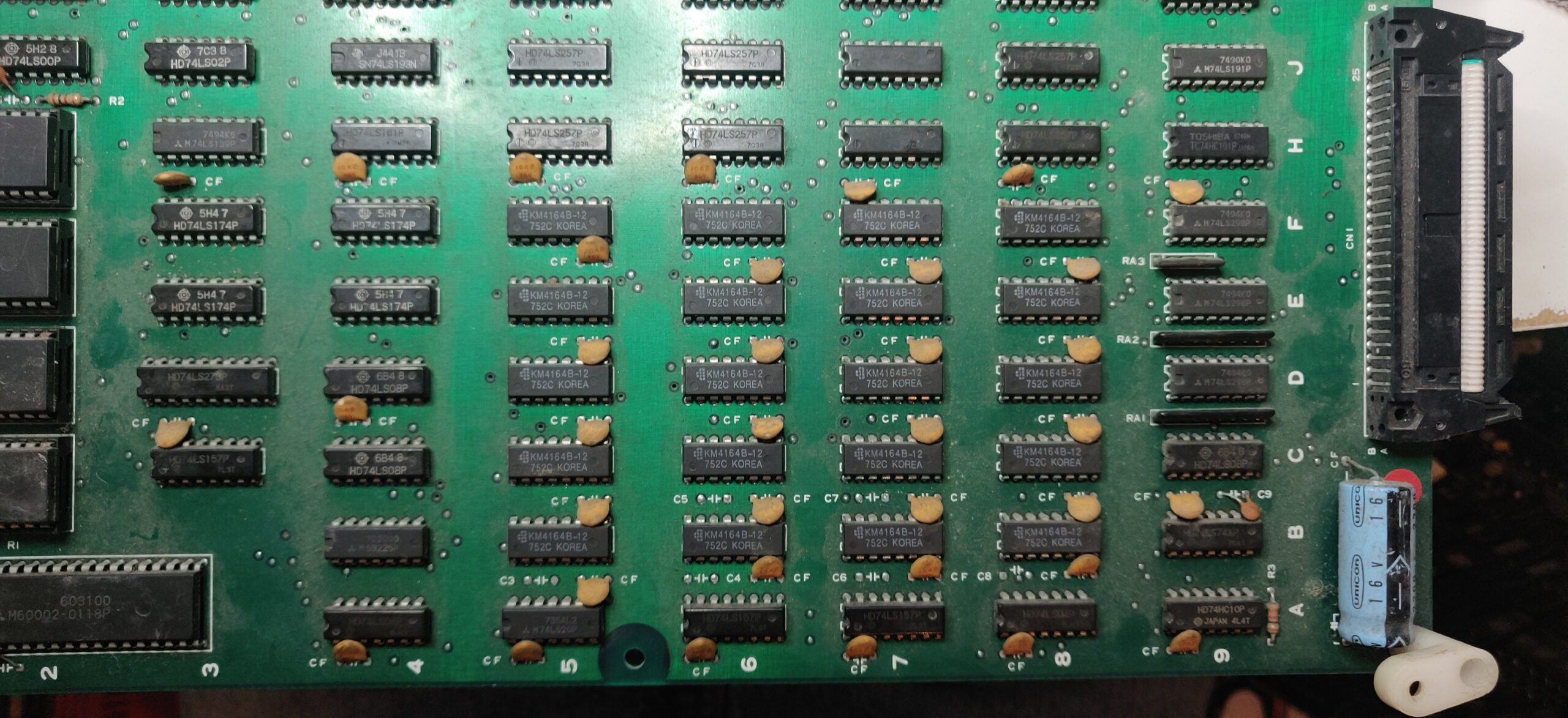
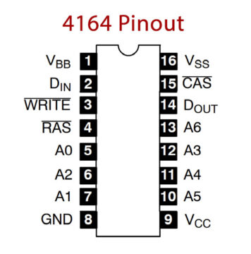
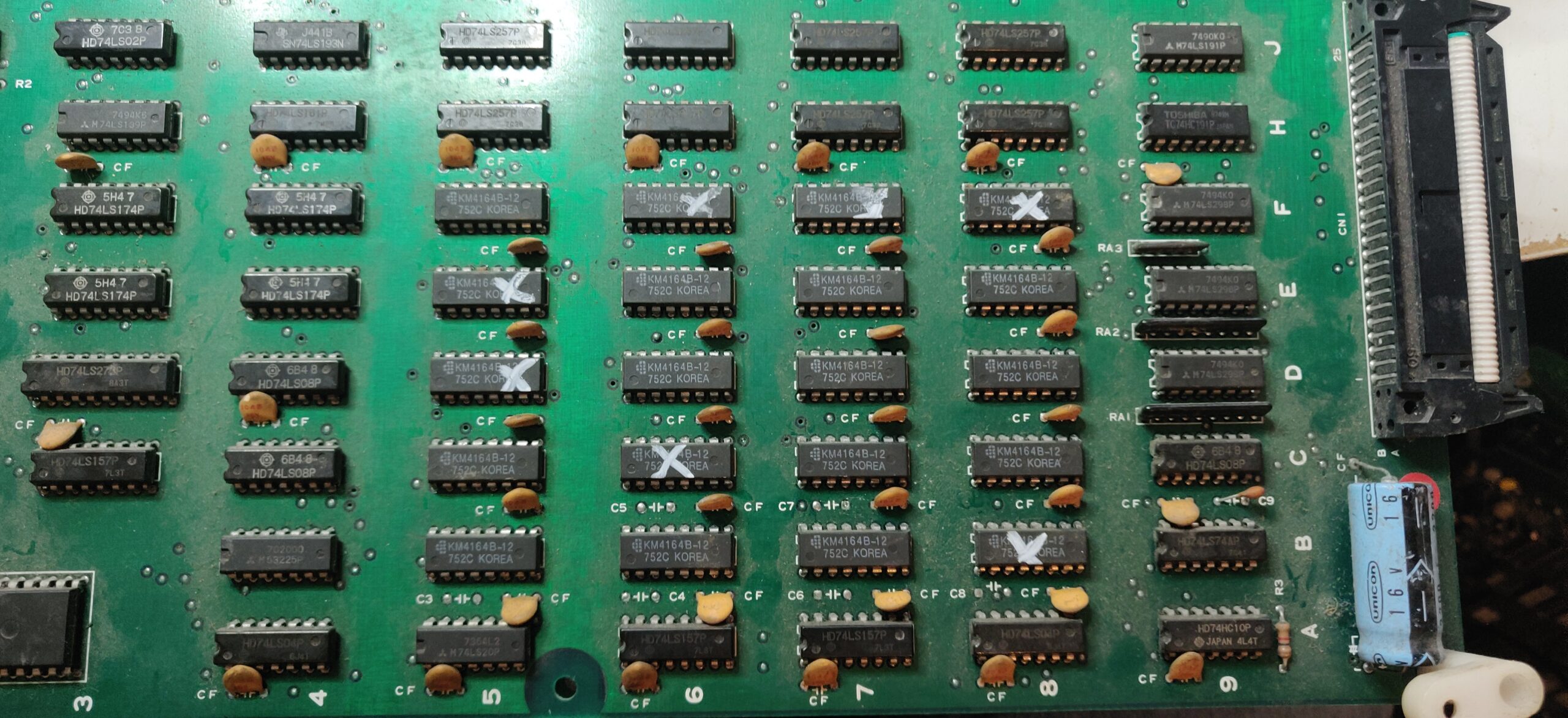
Background is back but the sprites are blinking, they are misplaced and have bad colors. Sprites are generated by the custom chip Mitsubishi M60002-0118P and displayed through twenty 4164 DRAMs. These are known for having a high failure rate. I will focus my investigations in this area:
Probing the D-OUT pins of these DRAMs (pin 14), 8 DRAMs out of 20 shows an output signal stuck low or even floating when the game has to display sprites:
I pulled these 8 D-RAMs:
All of them were confirmed bad out of circuit.
I fit 8 brand-new replacement DRAMs. Some sprite glitches are still visible – two other DRAMs have just gone bad. I took those out and replaced them. Now the sprites and backgrounds appeared to be rendering properly. However, the sprites motion is still jerky.
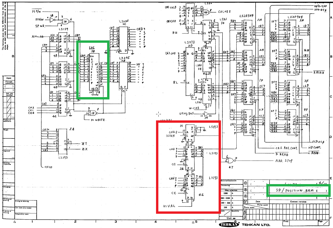
Rygar shares the same hardware as Silkworm and has schematics available. In the schematics, we can see that two 6116 SRAMs handles foreground and background graphics and a third one is dedicated to sprite positioning (SP/POSITION.RAM as per the schematics). This is the area I will inspect.
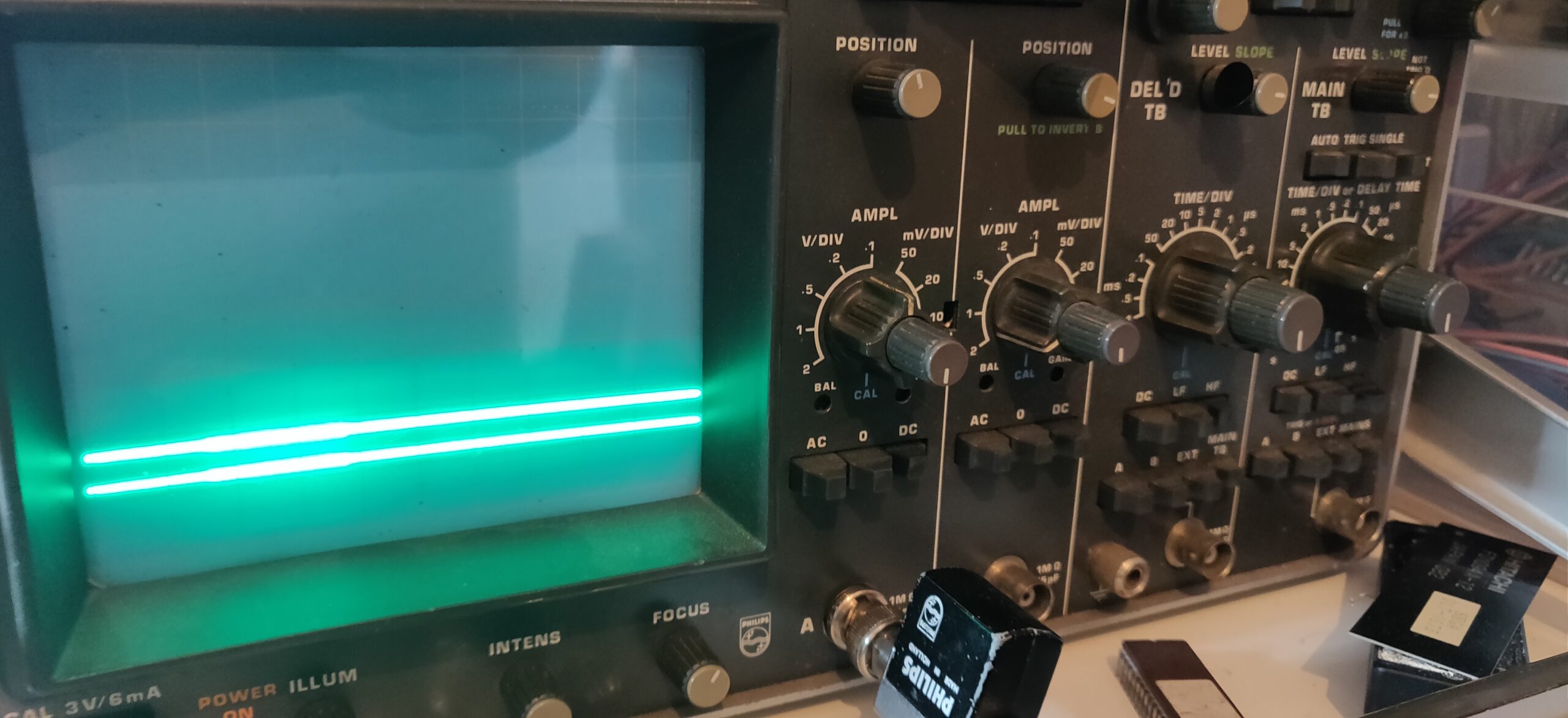
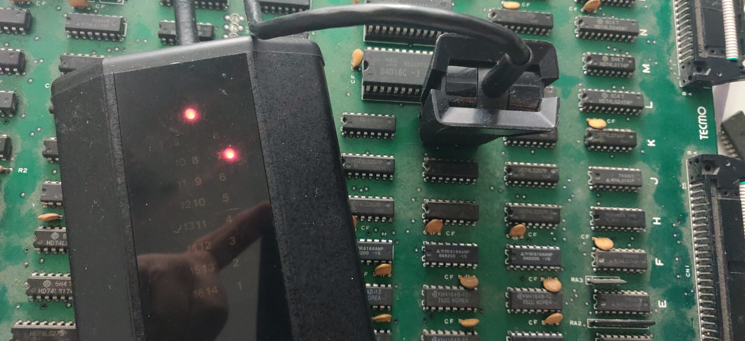
Inspection of the SRAM chip at location 6L doesn’t show anything abnormal. While probing around the area, I came across a signal stuck high on a 74LS193 binary counter (BORROW output) located at 7K. I double-checked it with my logic comparator:
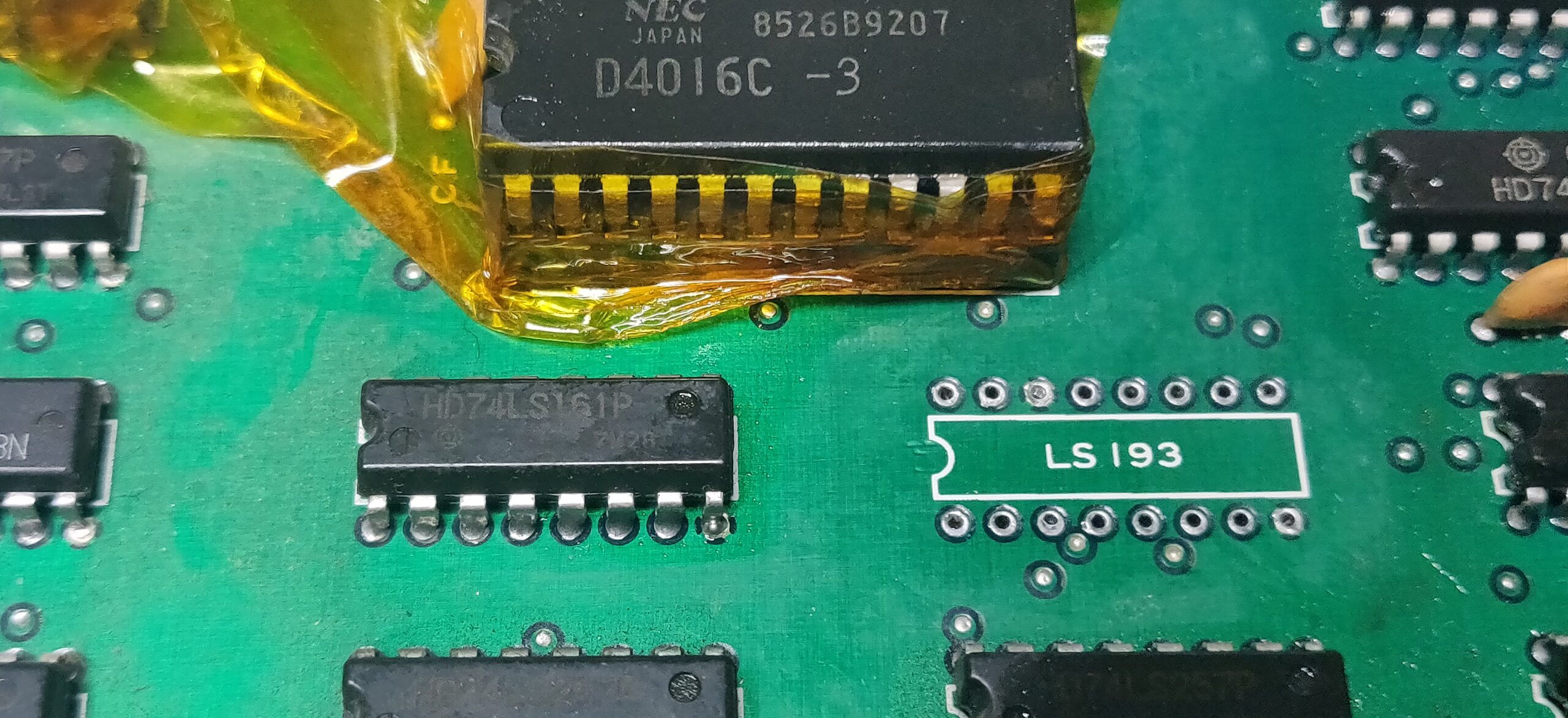
Red light indicated a bad output – I pulled the suspect:
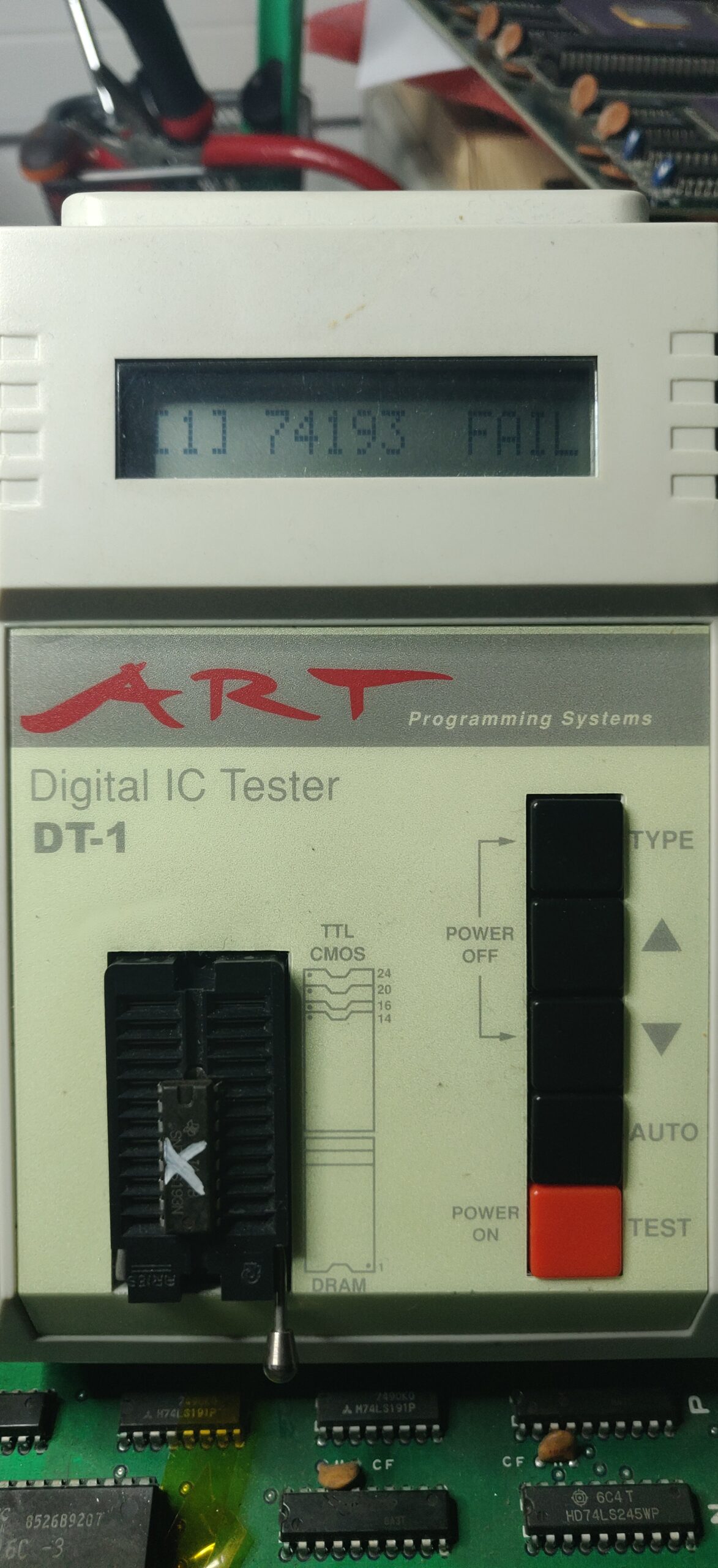
Confirmed bad out of circuit:
Replacing this chip fixes the jerkiness. Game is perfectly playable. Sound and controls tested OK.
GeneralComments Off on New Section – Arcade PCB Encyclopedia
Apr132024
I’m introducing a new section of JAMMArcade.net that I believe will be very useful for arcade repair technicians – the Arcade PCB Encyclopedia.
I have long admired the Console 5 Wiki as a comprehensive source of information for video game consoles. A typical console page will have a capacitor list, describe common faults, and collect manufacturer white papers. The JAMMArcade.net Arcade PCB Encyclopedia will attempt to accomplish the same thing for arcade boards.
My goal is to eventually document the following information in one page each for most arcade boards:
High quality photos of the boards – both originals and bootlegs
Notable ICs and their function
Capacitor list
Common faults and solutions to those faults
Protection mechanisms
Schematics and Datasheets
Links to other reference resources on the Internet
Given the number of arcade games produced, it may take several years to assemble these resources for every game, but I want to at least start with the most popular and most documented ones.
The Encyclopedia launches today with information on three boards and I will try to write up 1 – 2 more each week – each one takes a while to research!
I highly value credit for the original researchers and strive for proper attribution. Please contact me if you notice any mistakes in the Encyclopedia entries and I welcome other contributors as well.