Last Updated: 4/18/2024
Article Credit: ShootTheCore, Ikotsu, rtw, Trap15, ekorz, twistedsymphony, channelmaniac
The Seibu Kaihatsu SPI platform was offered in two configurations:
- Two Board – Main Board and cartridge ROM Board
- Region locked: Main Board must match country of cartridge ROM Board. This protection can be bypassed – see “Protection Mechanisms” below.
- Optional Stereo audio.
- Single Board
- Only runs the one game that was loaded onto it at the factory.
- Offered with two different audio setups- Yamaha YM-271-F or dual OKI MSM6295
- Mono audio only.
This article will address the two configurations separately.
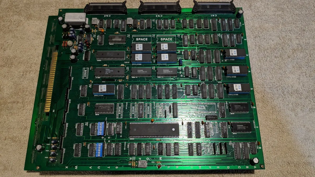
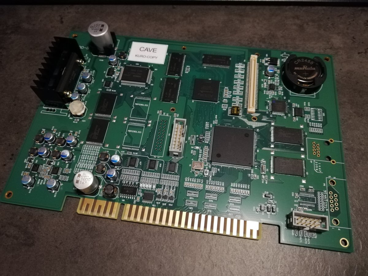
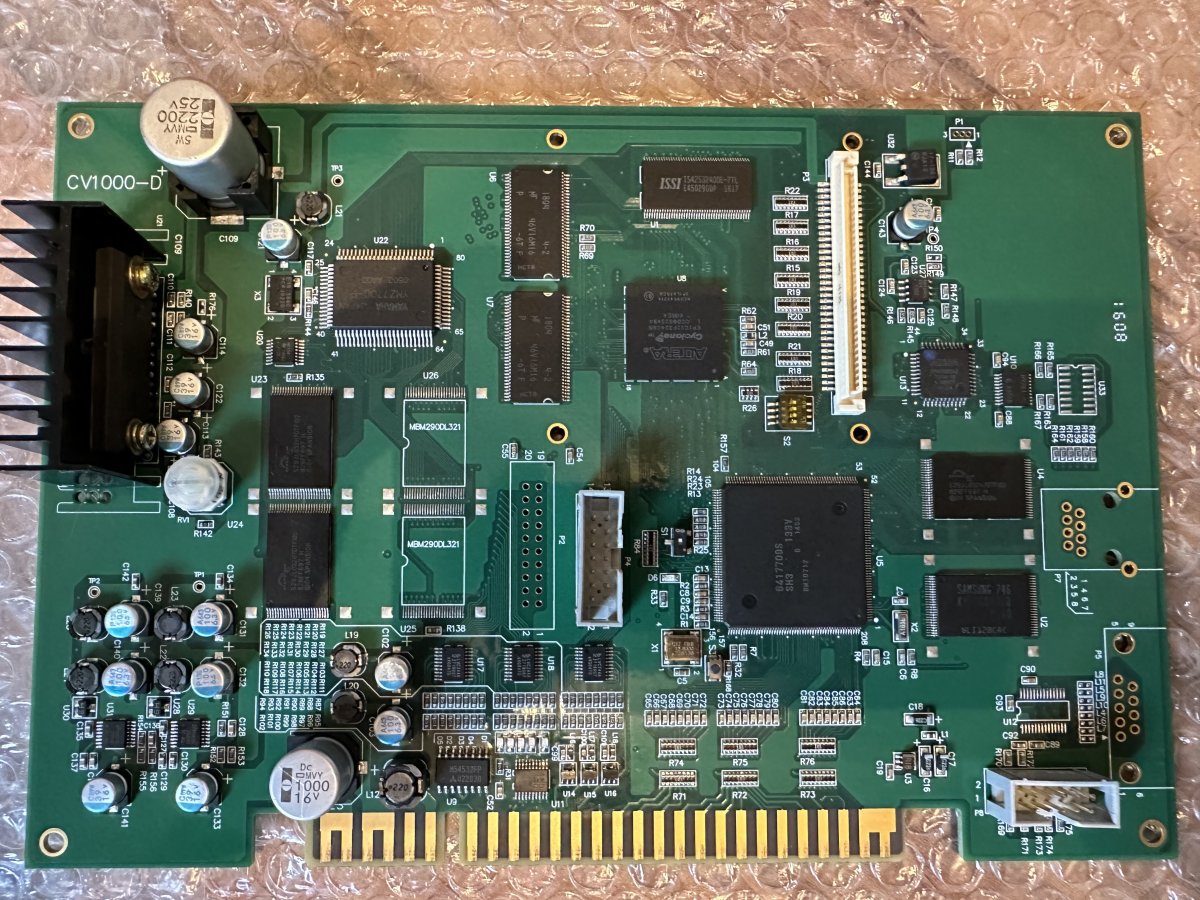
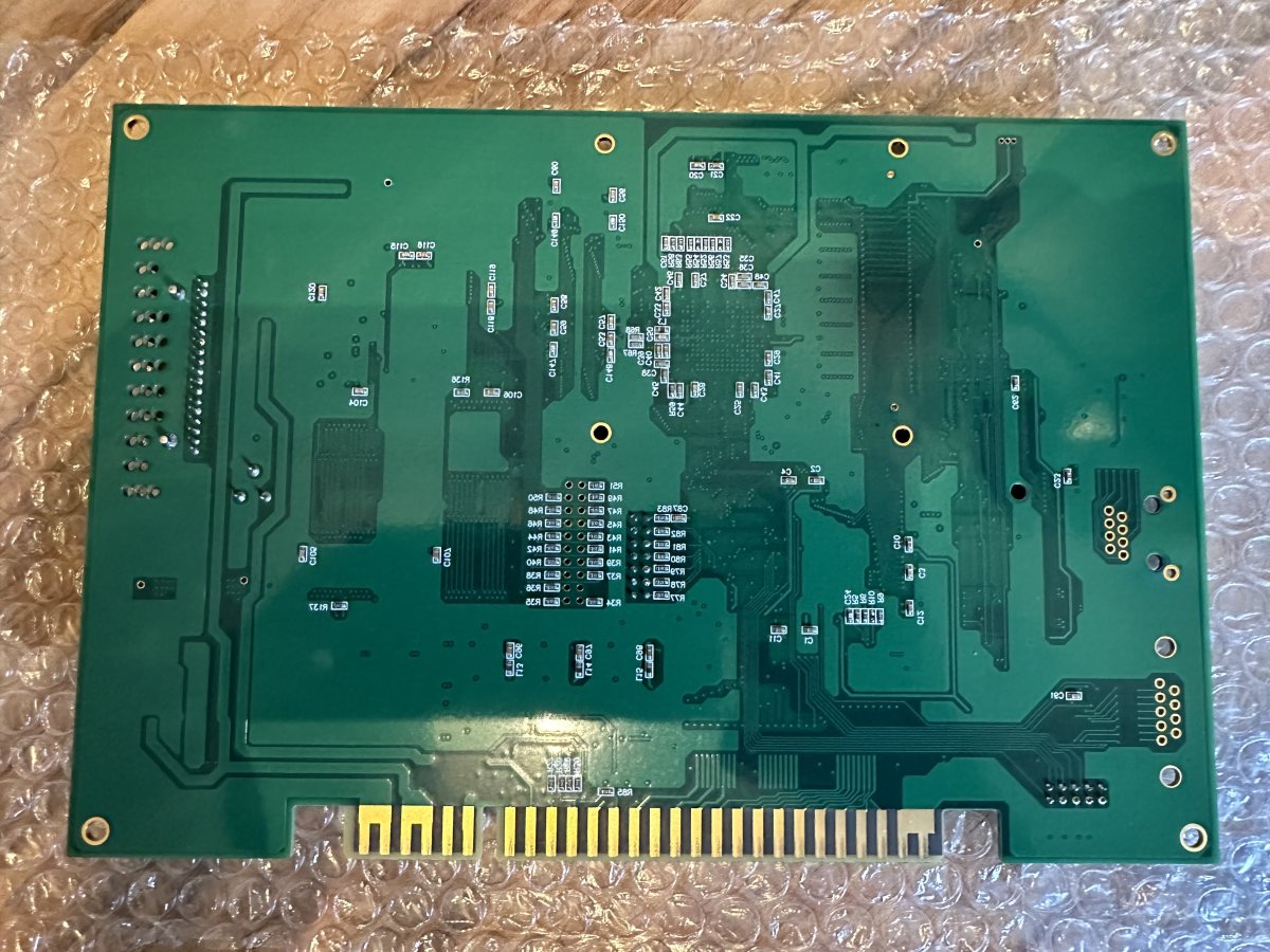
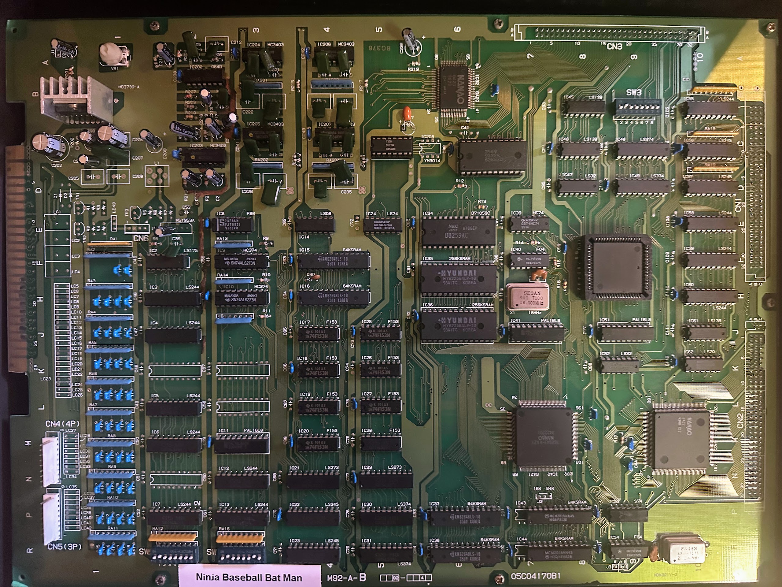
Two-Board Configuration: Main Board
The SPI main board contains all the processing logic to run the game. It was released with two revisions, both of which can run the same ROM game cartridges. The marking on the board for each revision is:
- (C)1995 SXX2C-MAIN V2.0
- (C)1998 SXX2D-MAIN V2.1
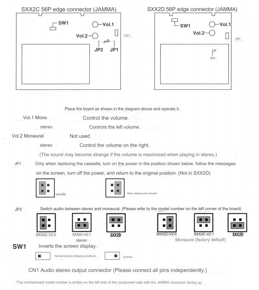
Stereo sound output is available on the two-board SPI configuration through the CN1 connection header. Everten sells a nice add-on board that adapts the CN1 header to standard RCA stereo audio ports.
https://shewfly.com/products/seibu-kaihatsu-spi-stereo-board-by-everten
https://www.candycabclub.com/product/everten_spi
The video and audio quality is said to be better with the SXX2C-MAIN V2.0 revision.
Source: https://shmups.system11.org/viewtopic.php?t=43308
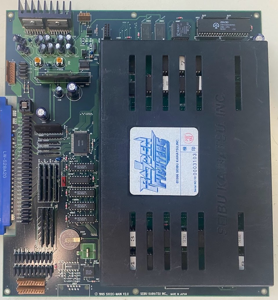
Photo Credit: ShootTheCore
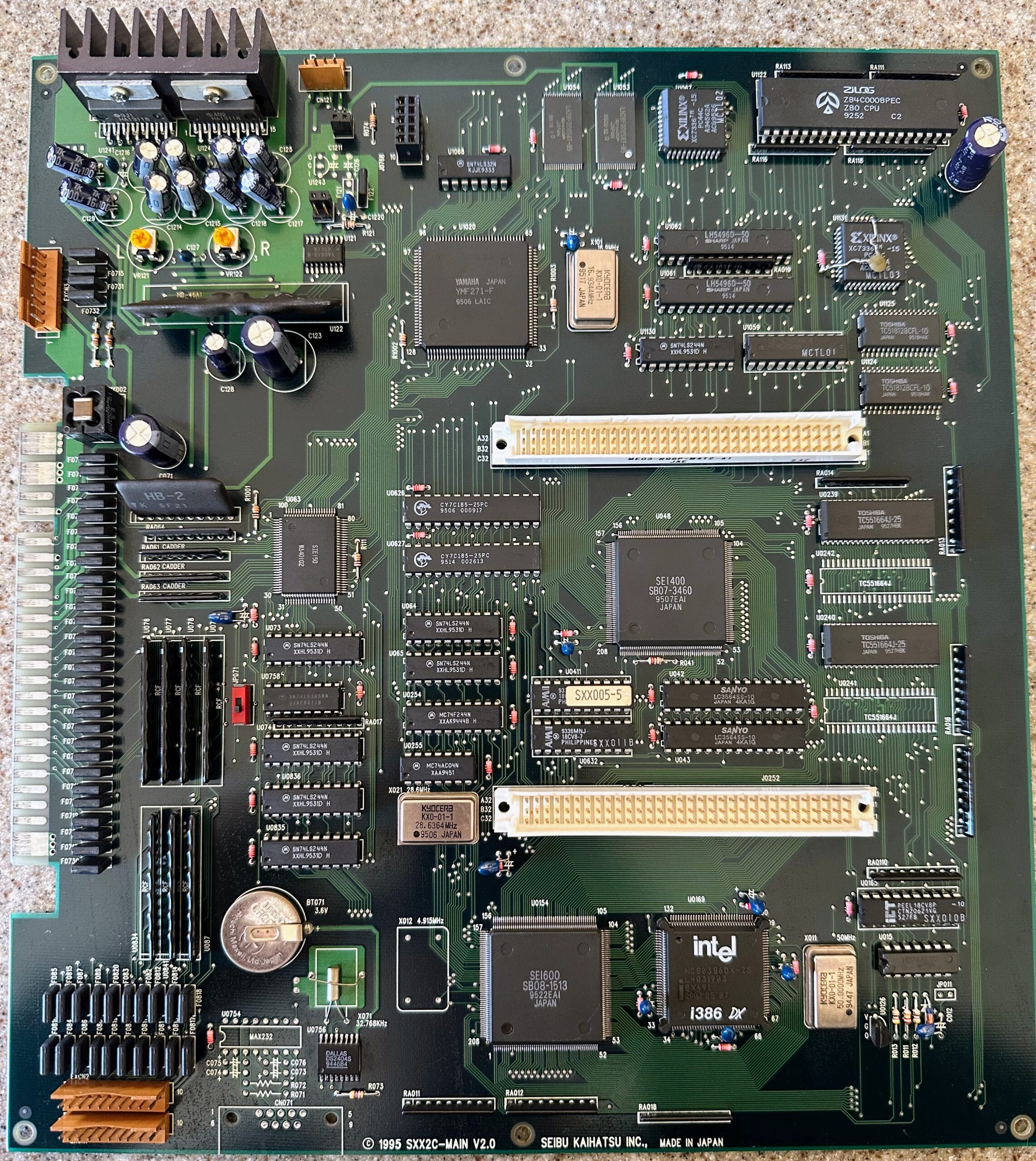
Photo Credit: ShootTheCore
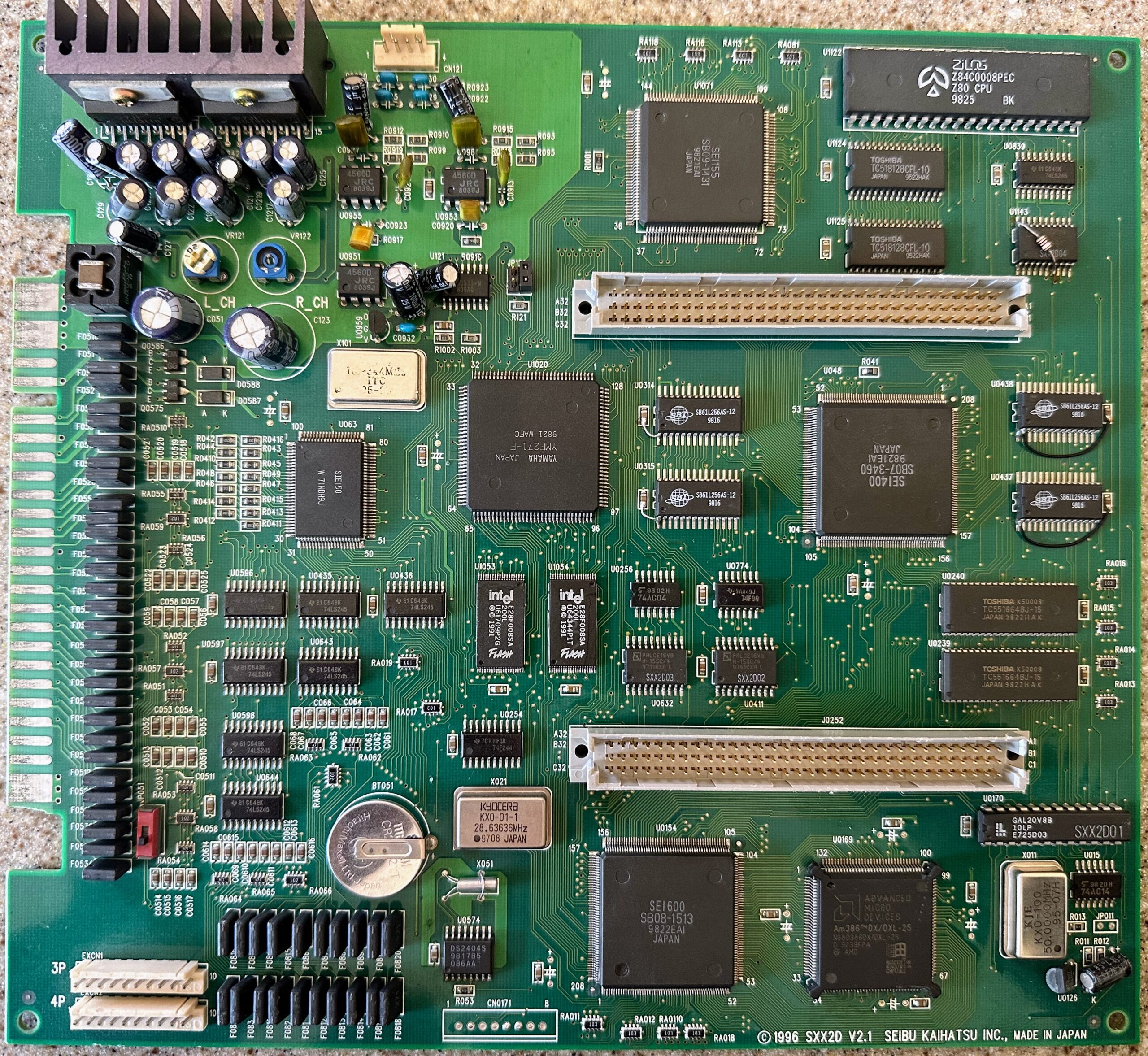
Photo Credit: ShootTheCore
The SPI system has onboard flash memory used for both region lockout and to store part of the game. The V2.0 board restricts write access to the flash memory by a jumper labeled JP072. The V2.1 board does not have any flash write access restriction jumper.
When swapping game cartridges, you will need to change the jumper (V2.0 only), install the new cart, power on, wait for the game to write to the flash memory (the message “NOW UPDATING. PLEASE WAIT A MOMENT.” will be displayed), power down and flip the jumper back (V2.0 only). Even after flashing, the ROM cartridge must stay attached for the game to operate.
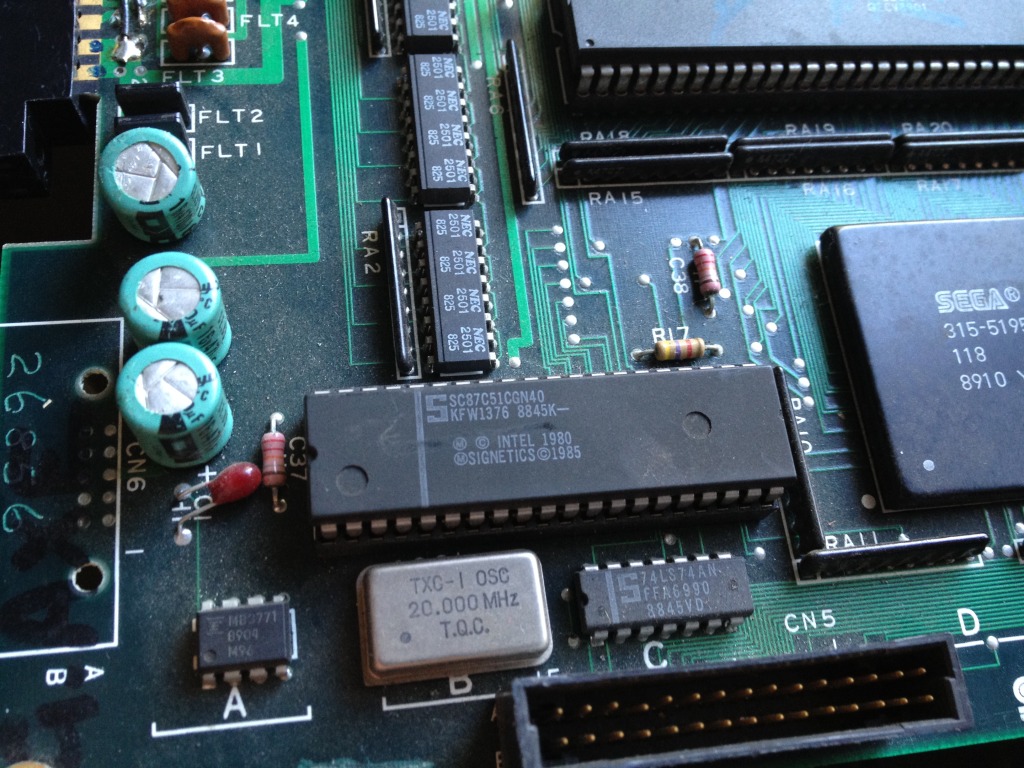
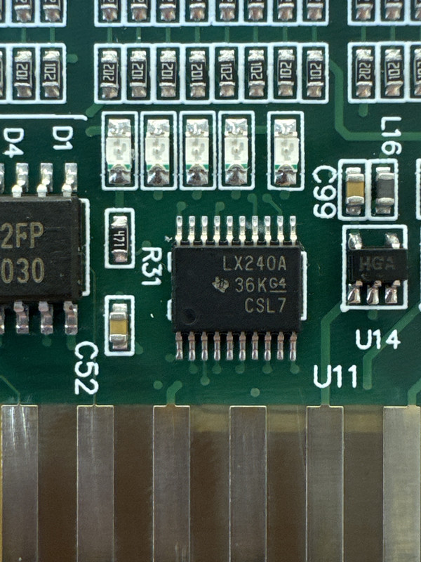
Notable ICs
| IC | Function | PCB Label |
| AM386DX/DXL-25 – OR – Intel NG80386DX25 | 25.0 Mhz Main CPU | U0169 |
| Zilog Z84C0008PEC | 7.15909 Mhz Audio CPU | U1122 |
| Yamaha YM271-F | Audio Processor and Flash Access | U1020 |
| Yamaha YAC513-M | Audio DAC | U1068 |
| Intel E28F008SA – OR – Sharp LH28F008 | 8 MBit FlashROM | U1053, U1054 |
| SEI400 | Graphics Rendering | U048 |
| SEI600 | Graphics Rendering | U0154 |
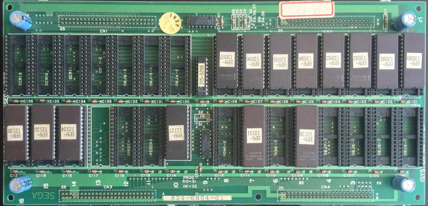
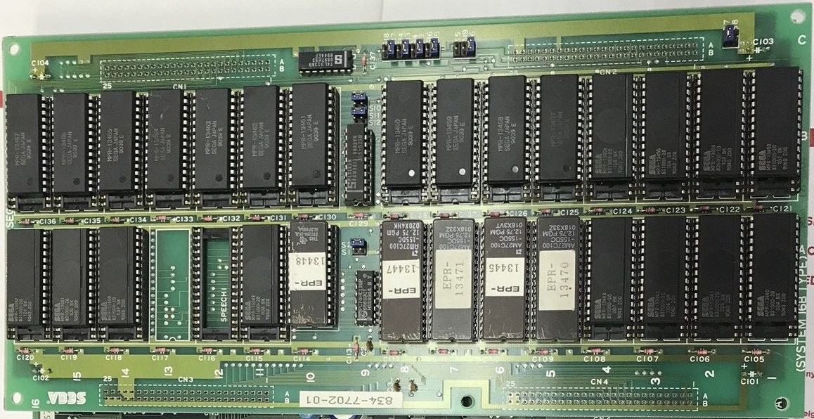
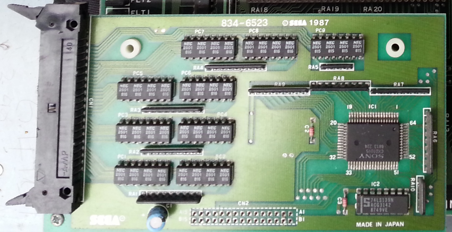
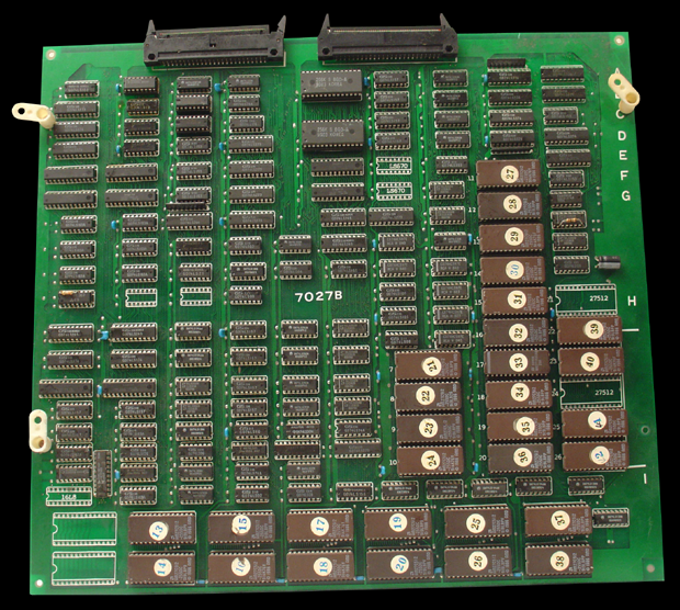
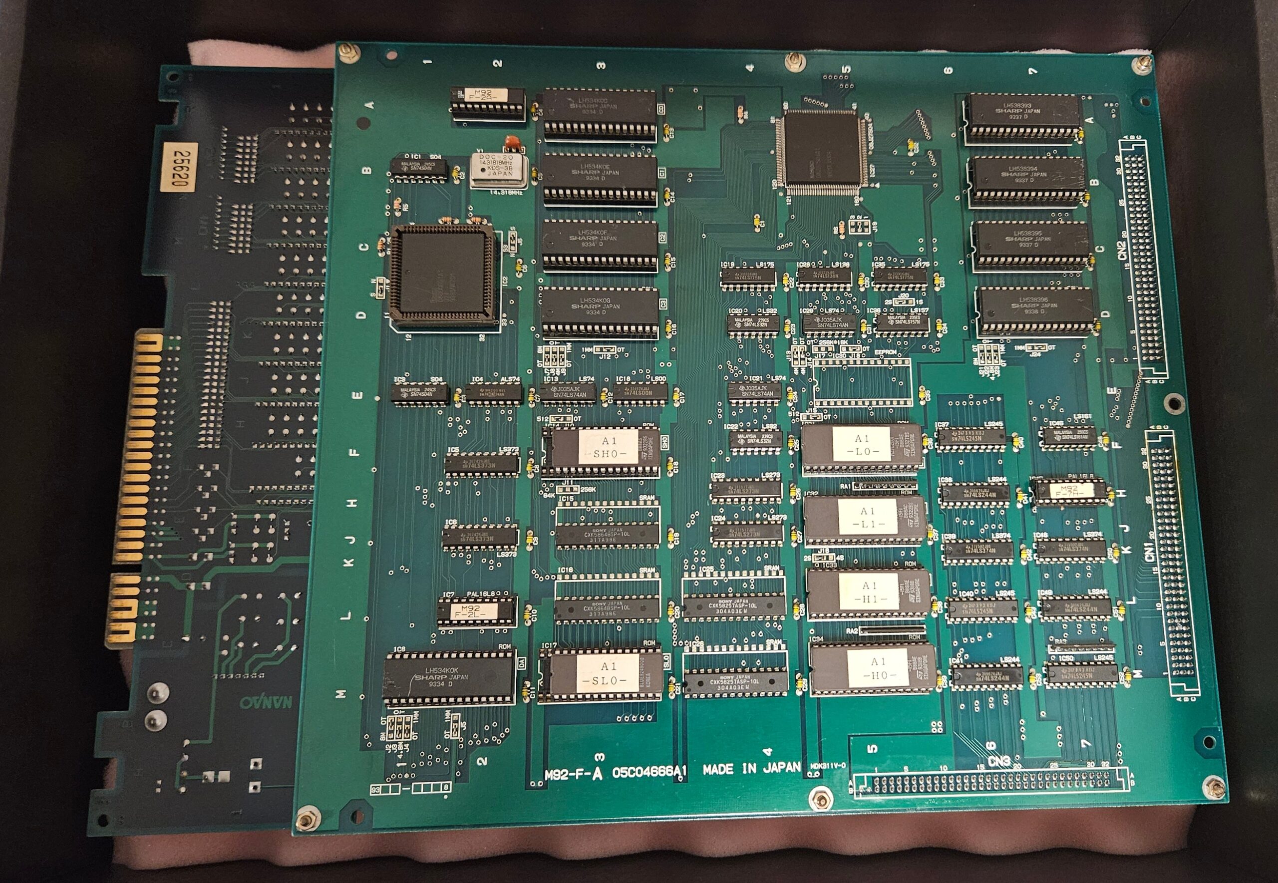
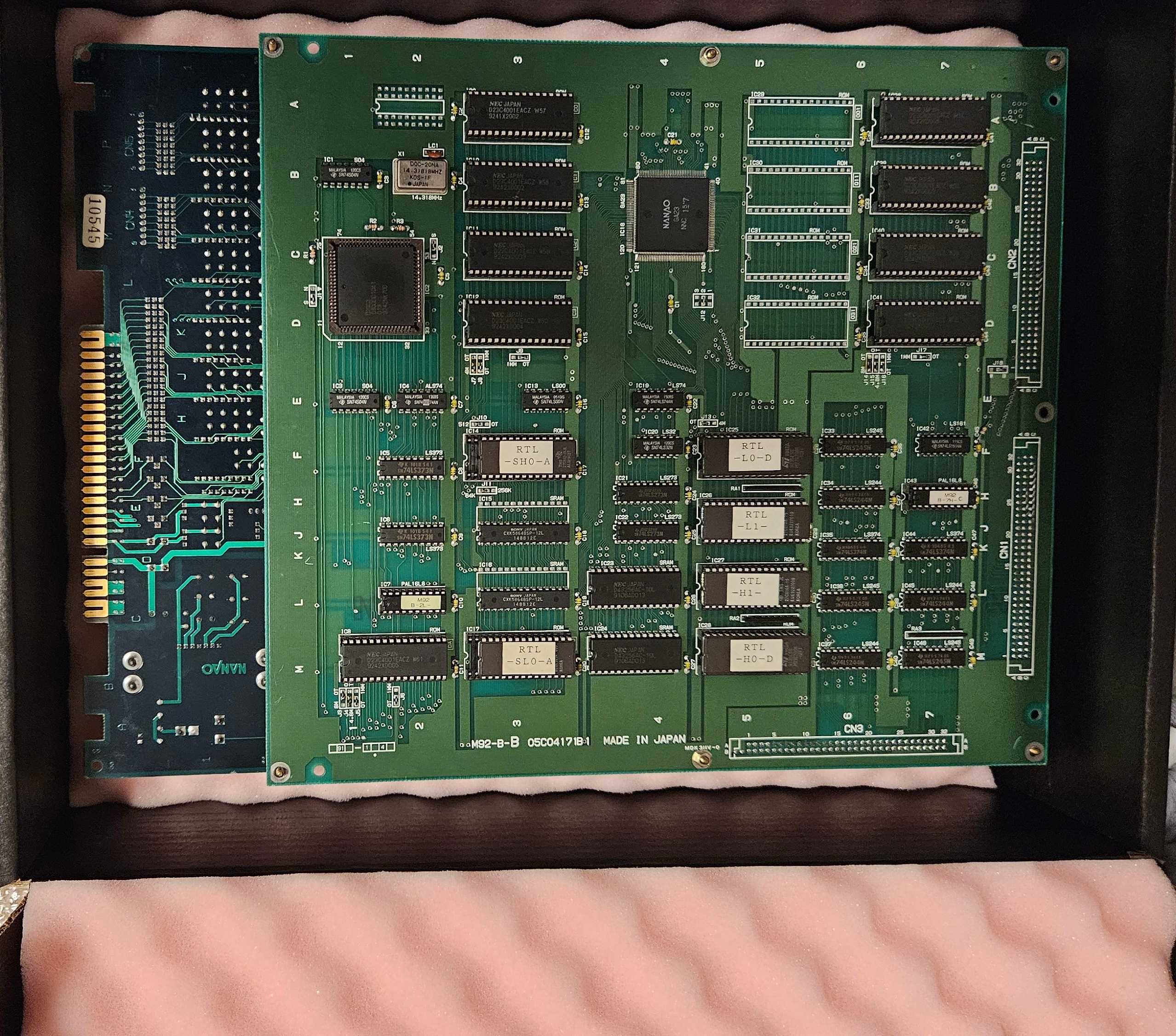
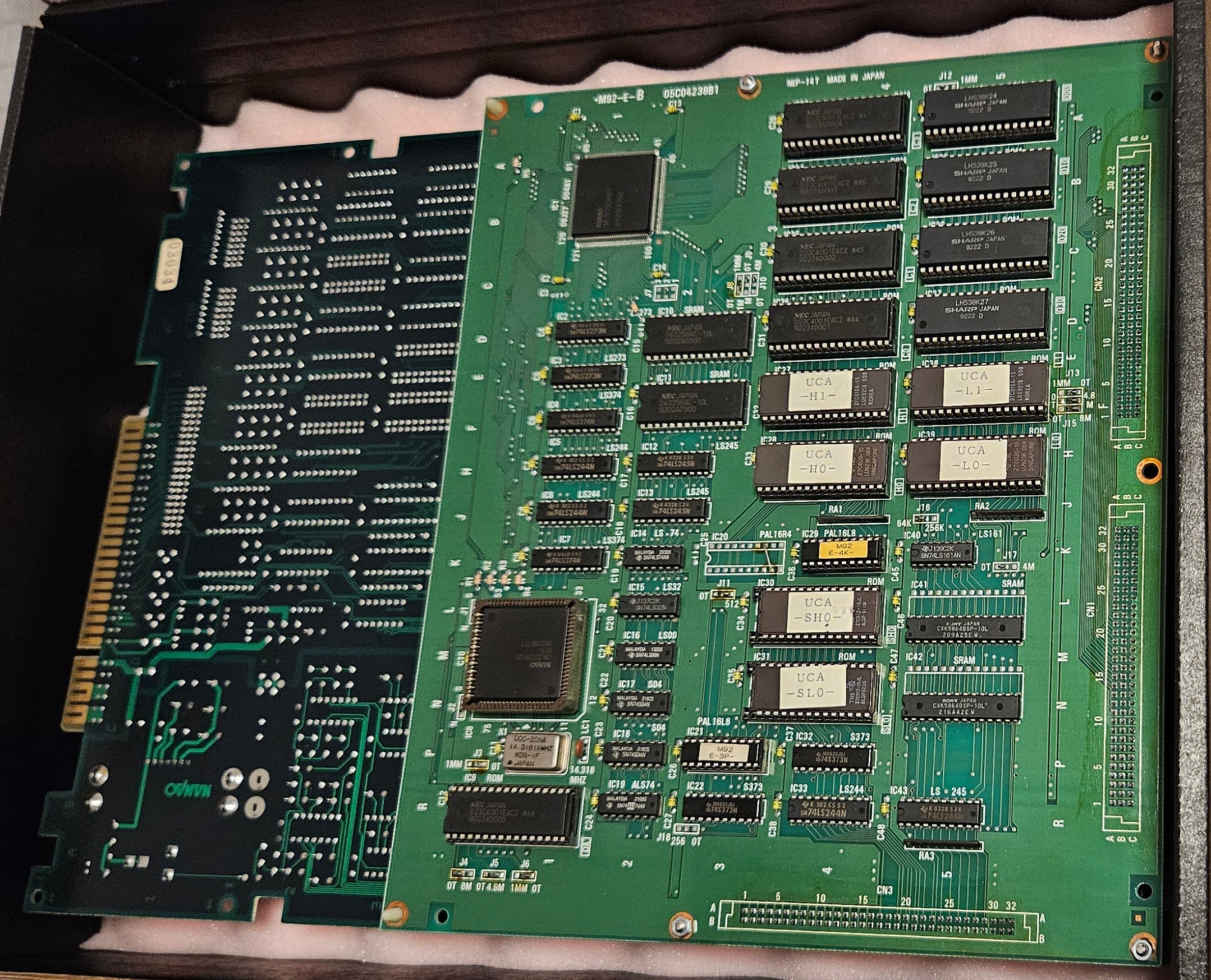
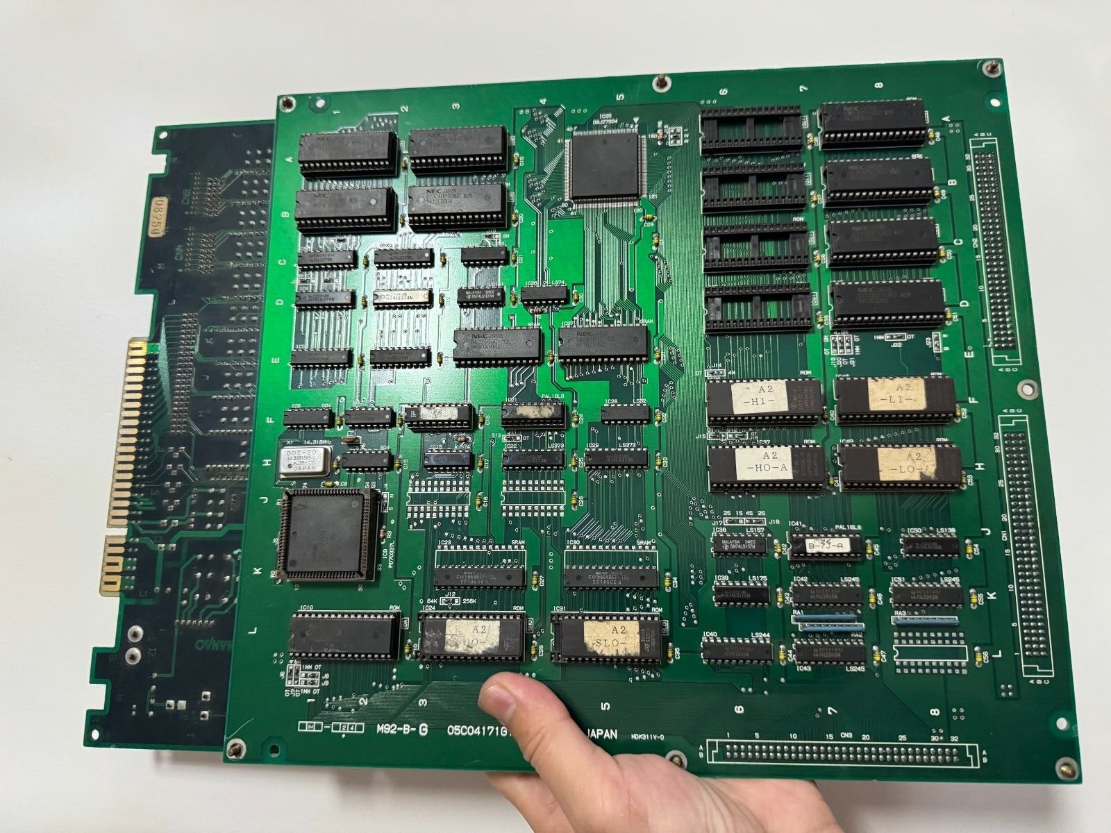
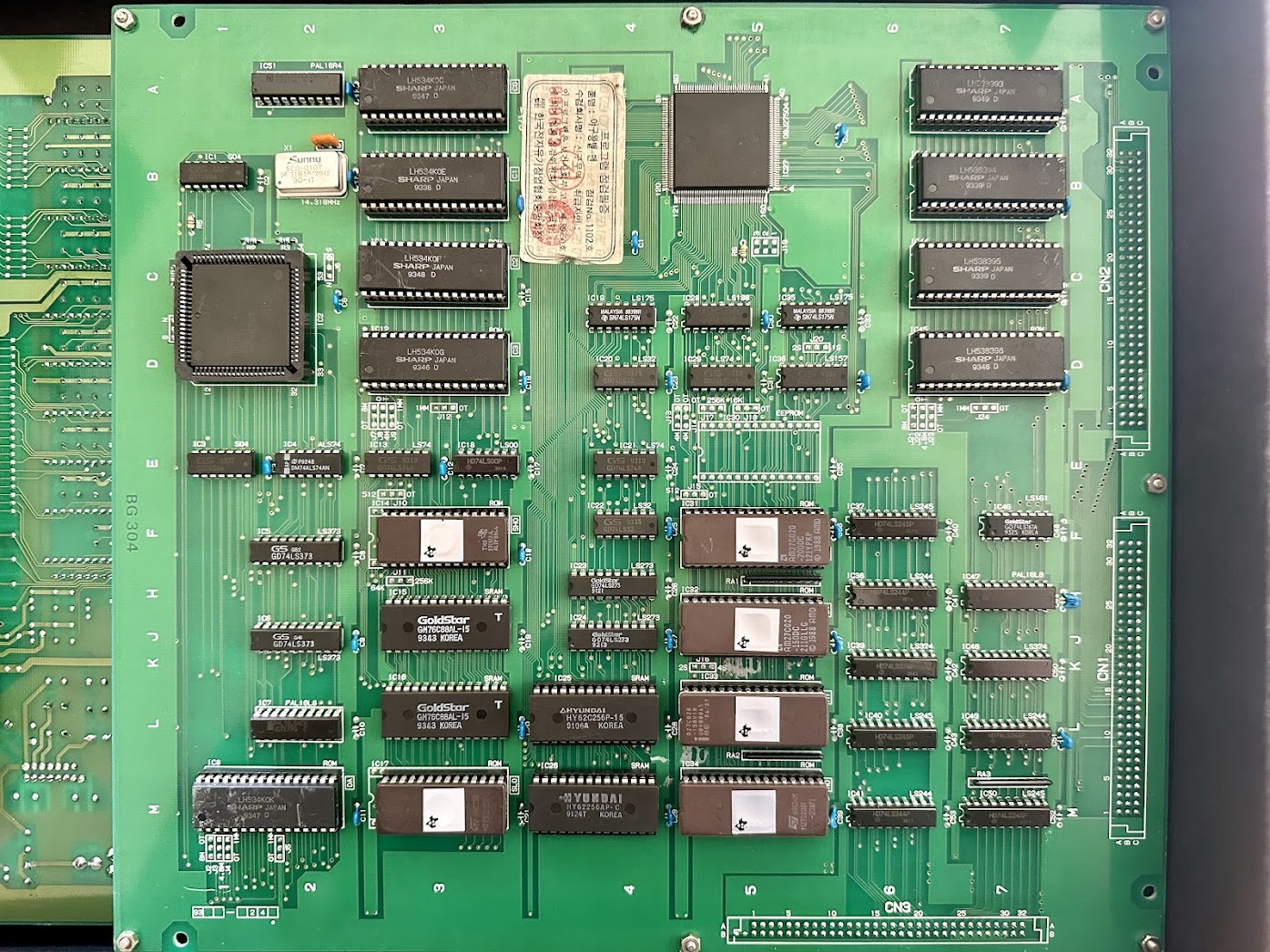
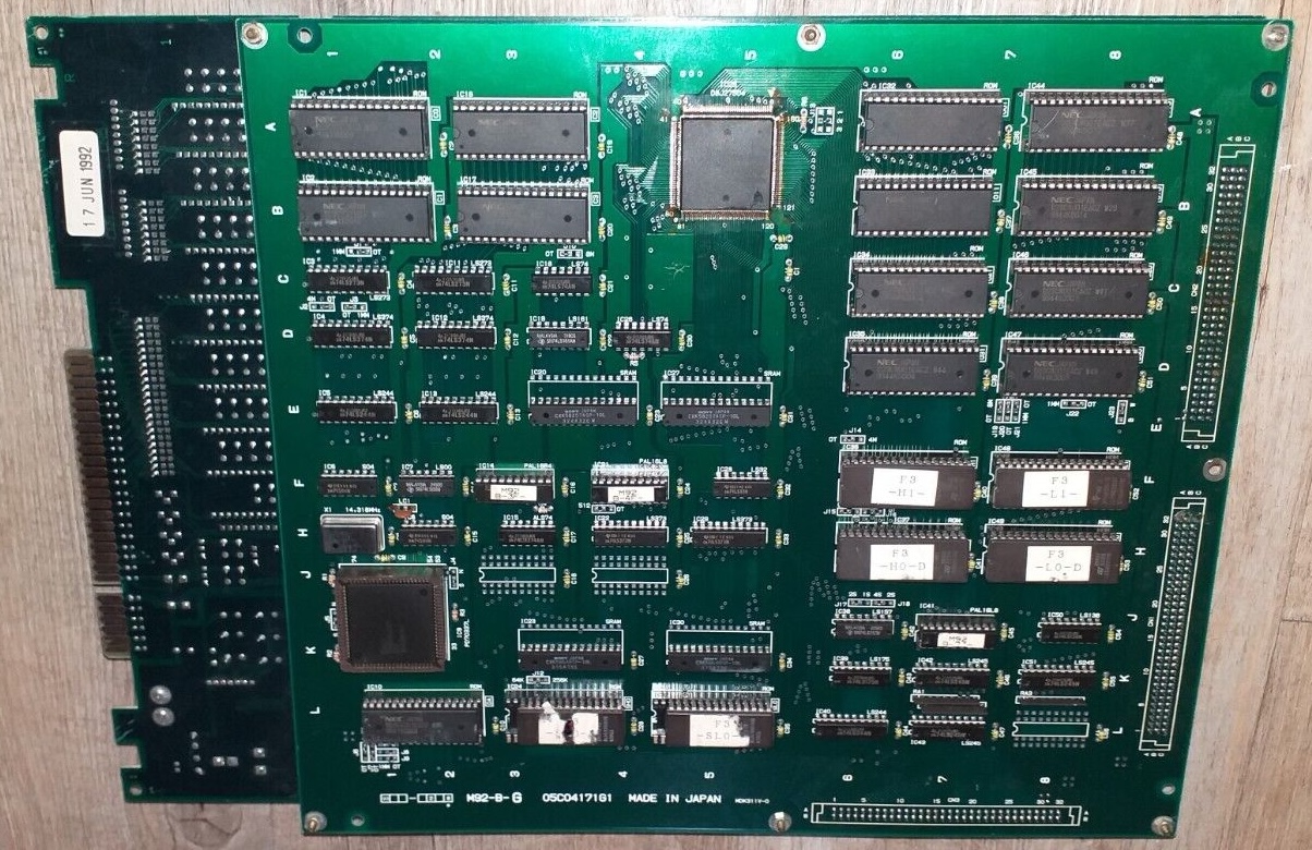
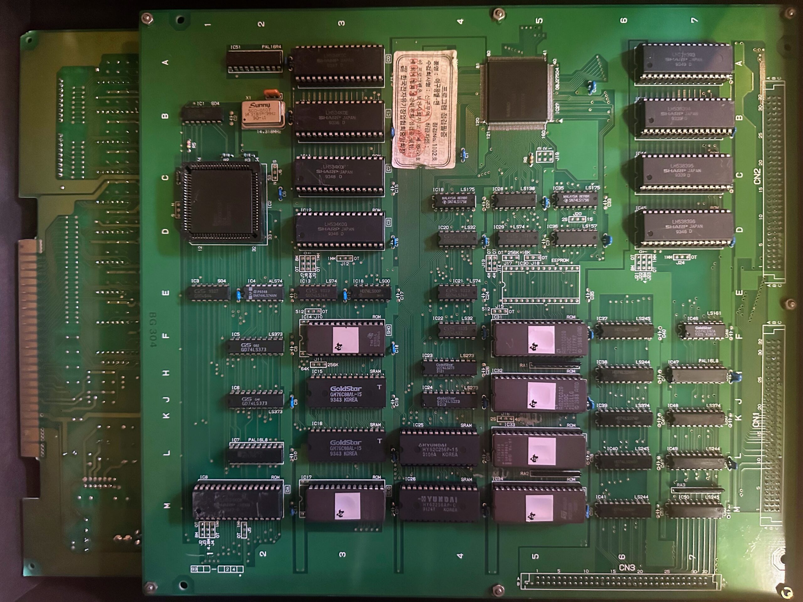
Two Board Configuration – ROM Cartridge Board
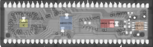
Cartridge boards include DIP socket EPROMs, SMD mask ROMs, SRAM and a custom decryption IC – see Protection Mechanisms below. It is not possible to reliably convert one SPI game cart to another at this time, although it is possible to upgrade the same game to a different version (ie Viper Phase One to Viper Phase One NV).
ROM Board model numbers
- SXX2C ROM SUB
- SXX2C ROM SUB2
- SXX2C ROM SUB4
- SXX2C ROM SUB8
- SXX2C ROM SUB10
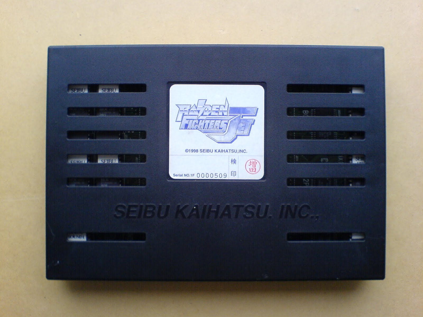
Photo Credit: Ikotsu
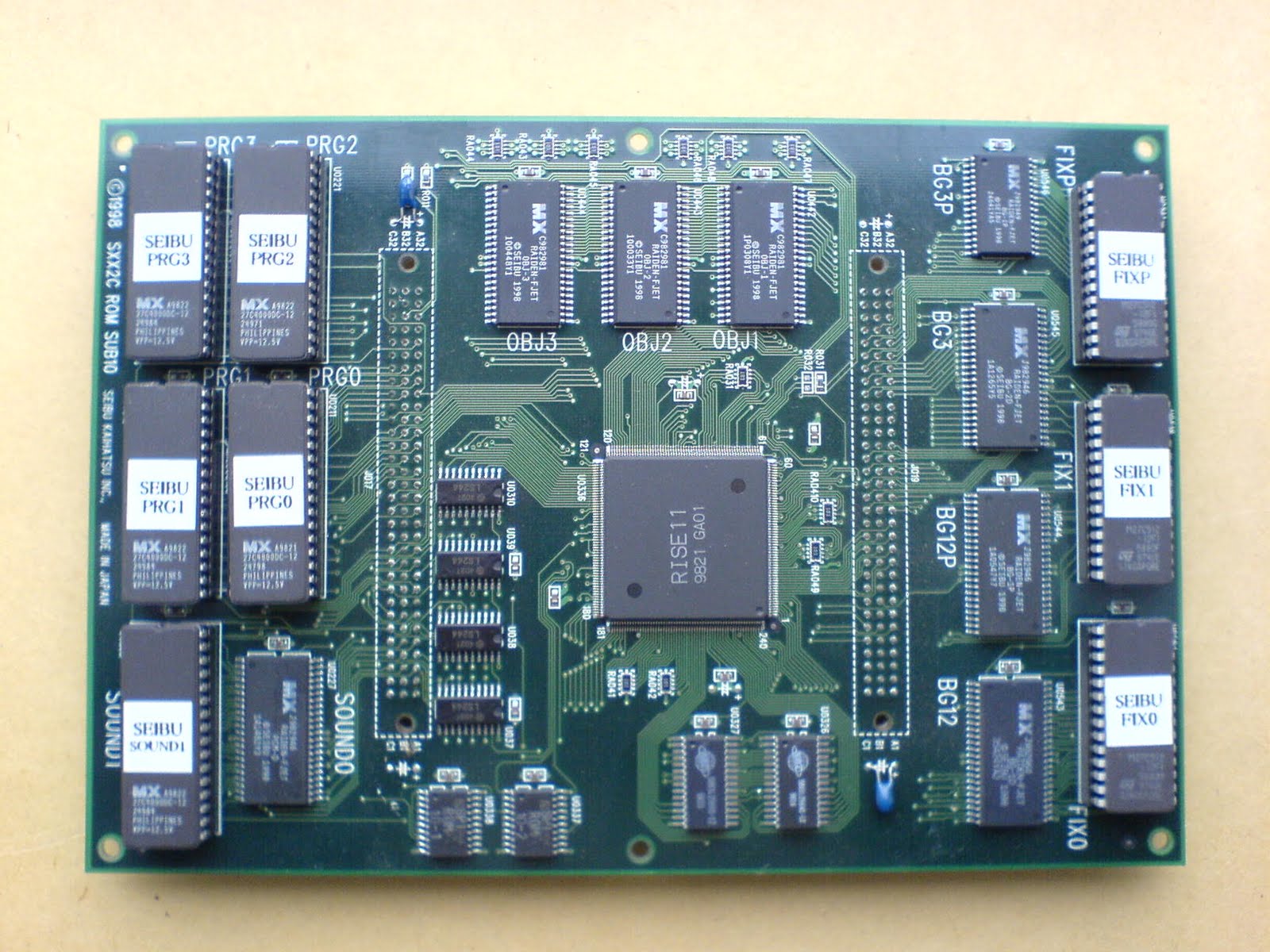
Photo Credit: Ikotsu
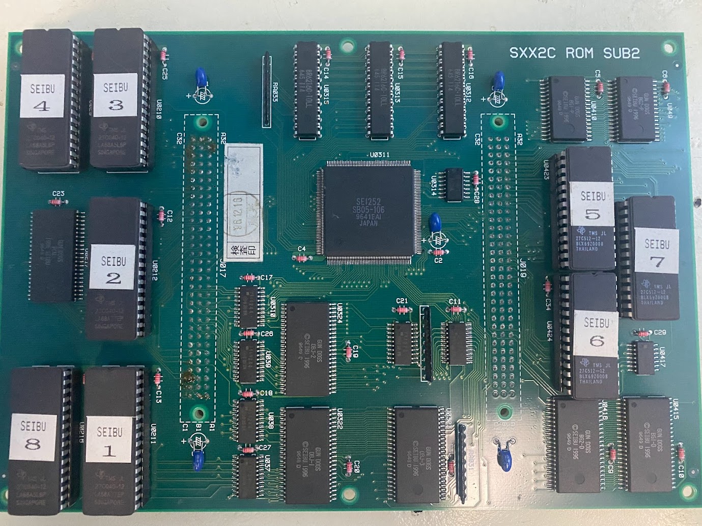
Photo Credit: ShootTheCore
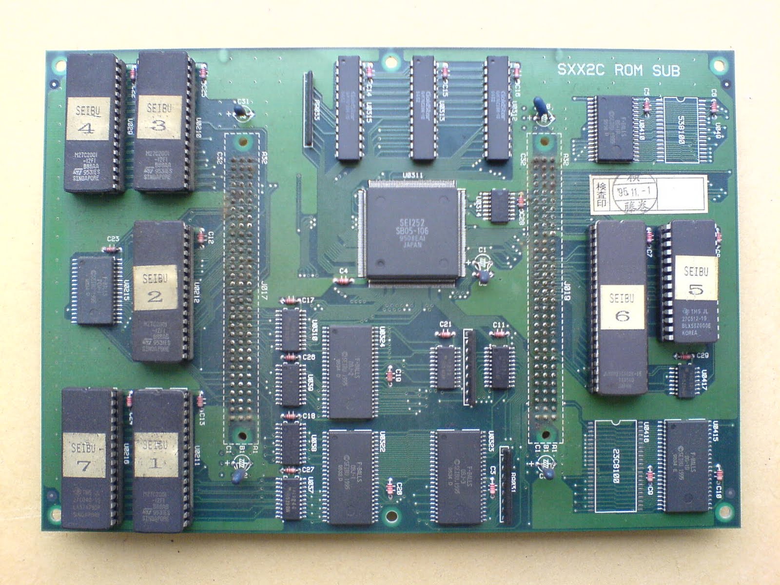
Photo Credit: Ikotsu
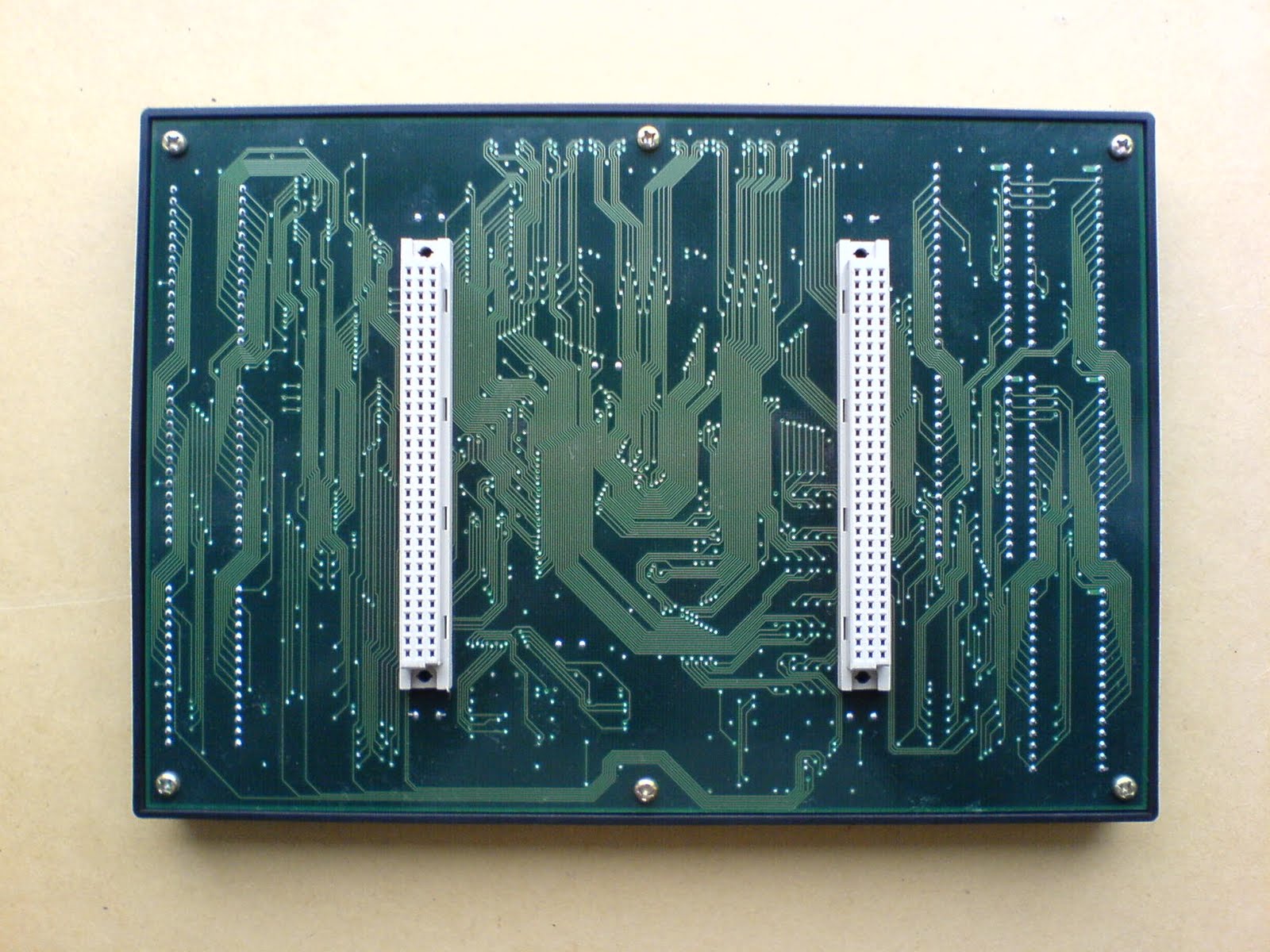
Photo Credit: Ikotsu
Common Issues and Quirks
CHECKSUM ERROR or HARDWARE ERROR (credit: rtw & Trap15 and channelmaniac)
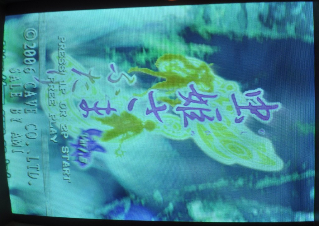
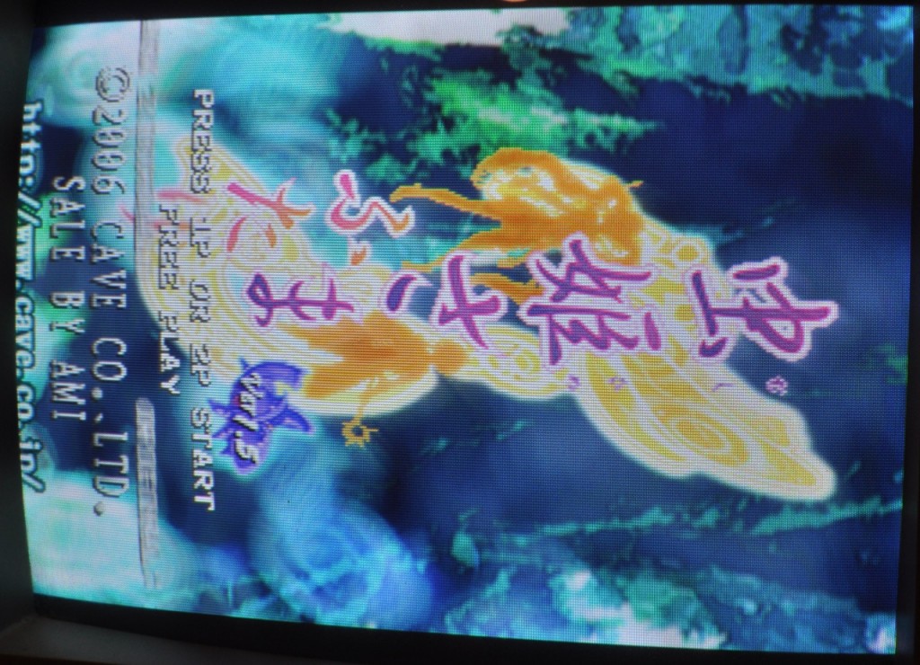
The two-board SPI platform stores part of the game inside onboard flash storage. The flash storage is also initialized from the factory with a country code. If the country code stored in the first byte of u1053 flash on the mainboard does not match the country code stored in the last byte of the PRG0 EPROM on the ROM cart then you will see the message CHECKSUM ERROR XXXX or HARDWARE ERROR XXXX during the flash process where XX is a two or four digit error code.
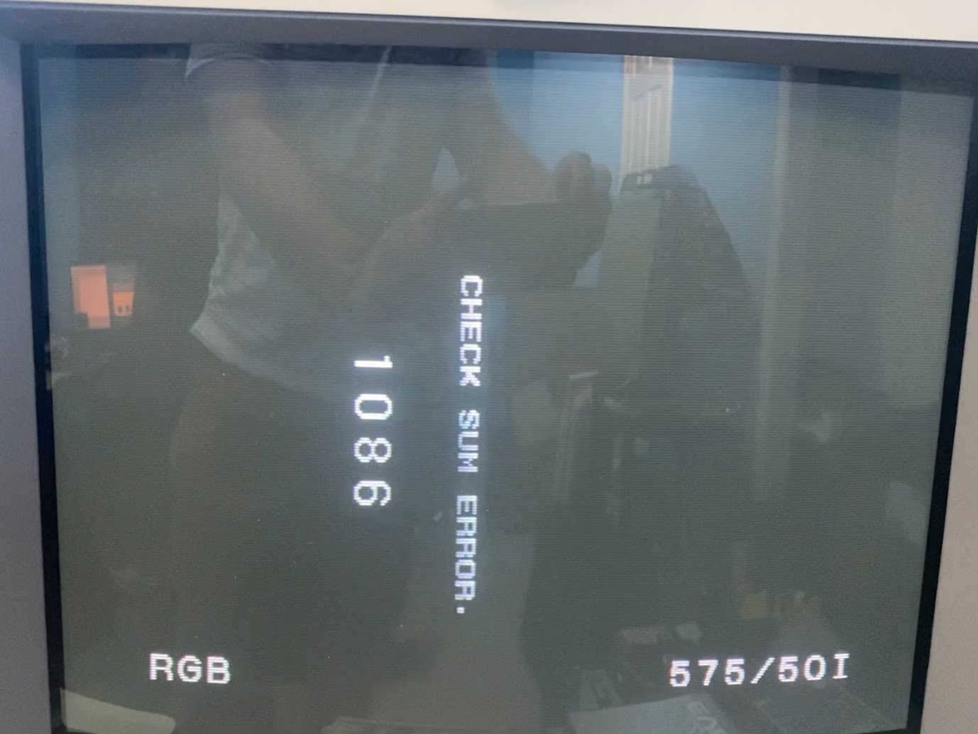
Photo Credit: ShootTheCore
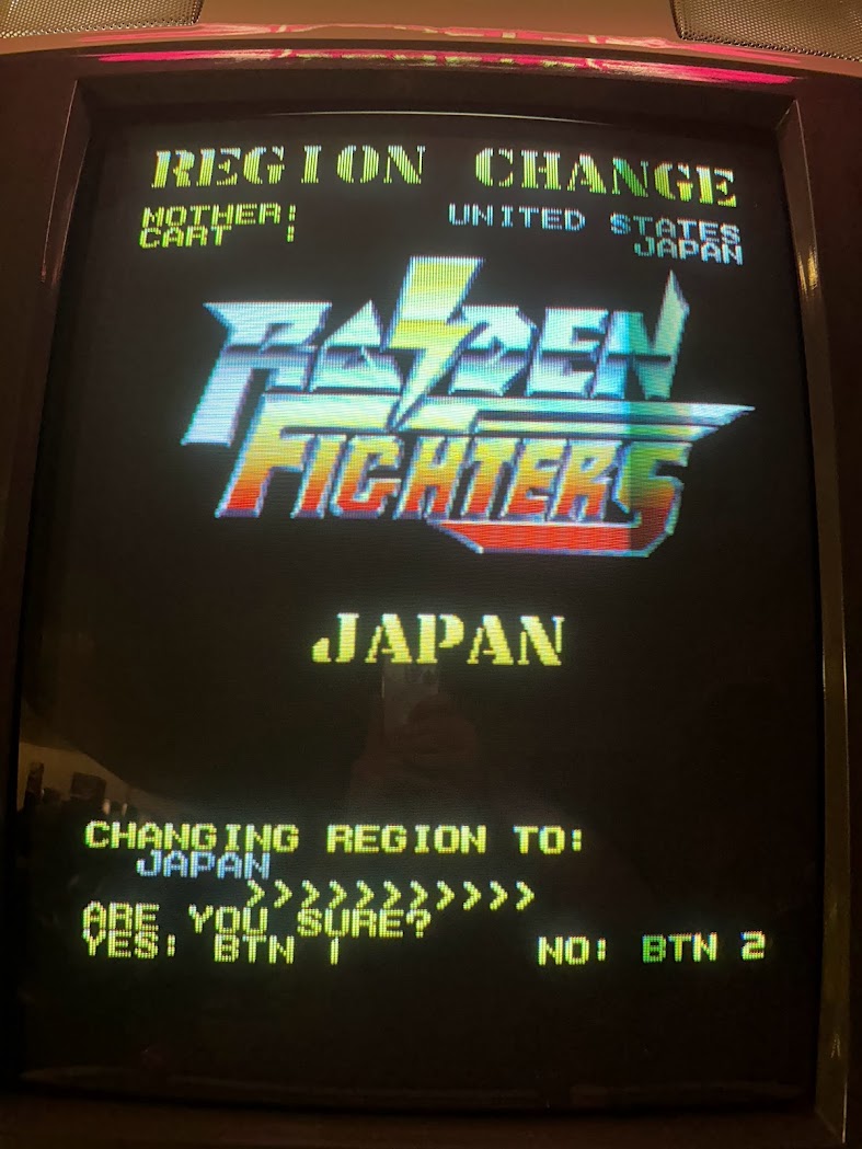
Photo Credit: ShootTheCore
It is possible to desolder the u1053 flash chip from the main board to reprogram it with a new code. A list of the country codes is in the opening comments of the MAME driver.
Alternatively, Trap15 developed a software solution named SPI Revive that can rewrite the country code on the mainboard by swapping the PRG0 EPROM on a Raiden Fighters or Raiden Fighters 2 cart. If SPI Revive is unable to change the country code then the u1053 flash chip should be replaced.
SPI Revive: https://bitbucket.org/trap15/spi_revive/src/master/
Source: https://shmups.system11.org/viewtopic.php?t=62636
There have also been cases where the flash chips are holding the correct country code data but the board isn’t reading that data correctly. The Yamaha YM271-F sound chip controls access to the flash storage, so check the connections and traces on it.
Reflowing the solder on all of the large SMD ICs is recommended for HARDWARE ERROR and CHECKSUM ERROR messages if the earlier methods of writing the country code do not resolve the problem.
Credit: ChannelManiac
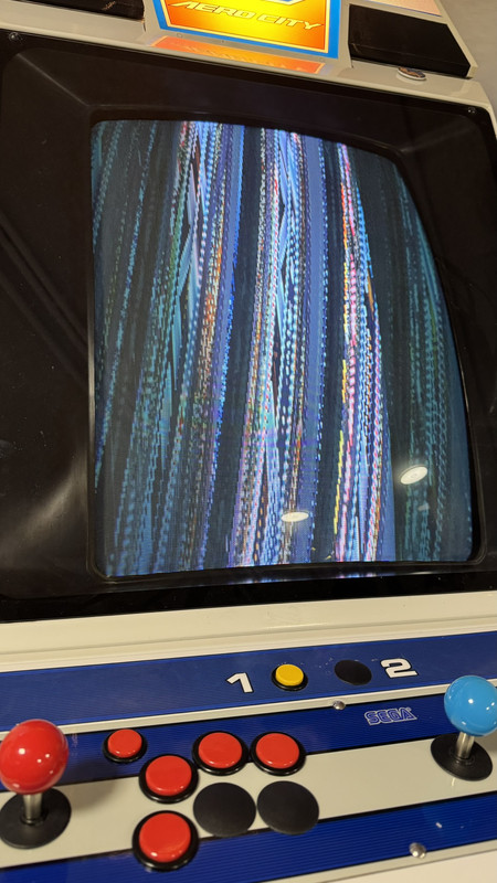
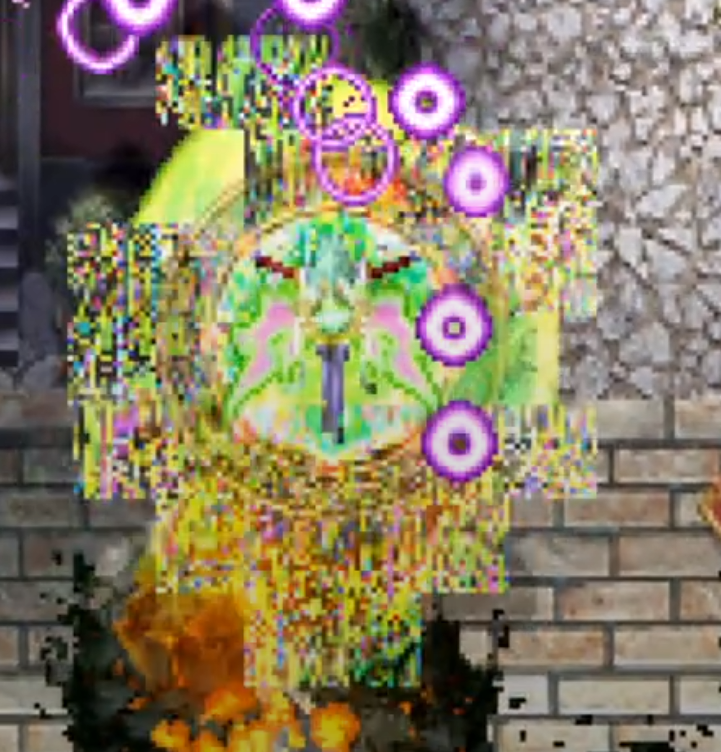
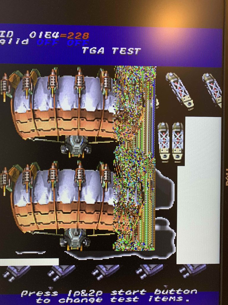
Boot Failure or Vertical Lines (jailbars) through graphics (credit: twistedsymphony)
It is common for the large SMD ICs to have pins separate from the PCB due to board flexing.
If an SPI board fails to boot at all on a known-good ROM cartridge, try reflowing the solder on each SMD IC, starting with the 386 Main CPU – it seems particularly susceptible to this issue.
If an SPI board has vertical lines running through the graphics, reflow the solder on the two SEI400 and SEI600 graphics rendering ICs.
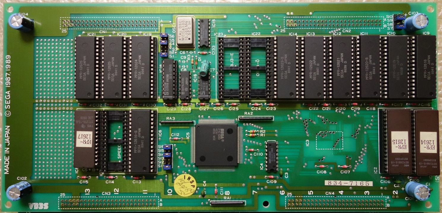
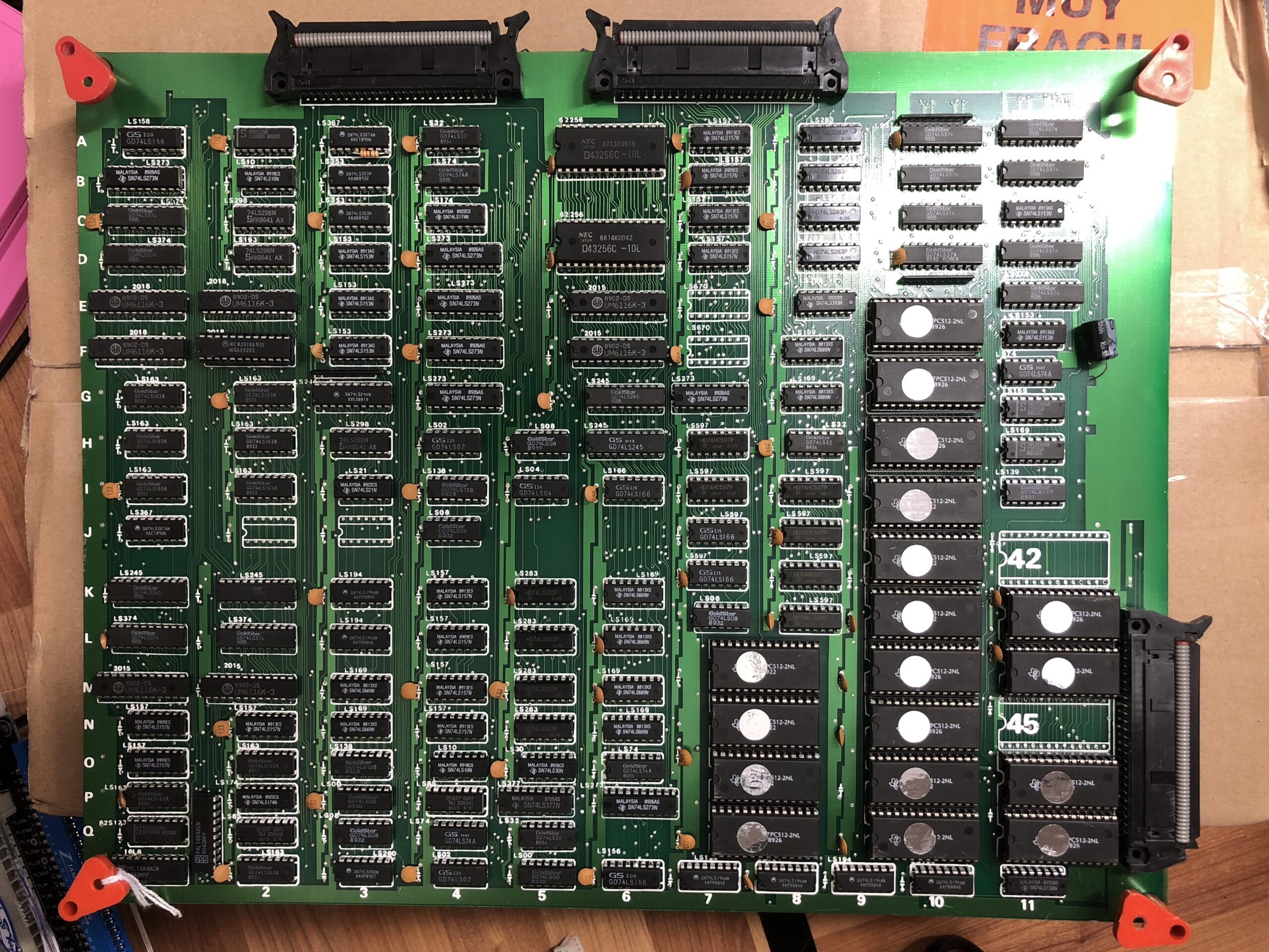
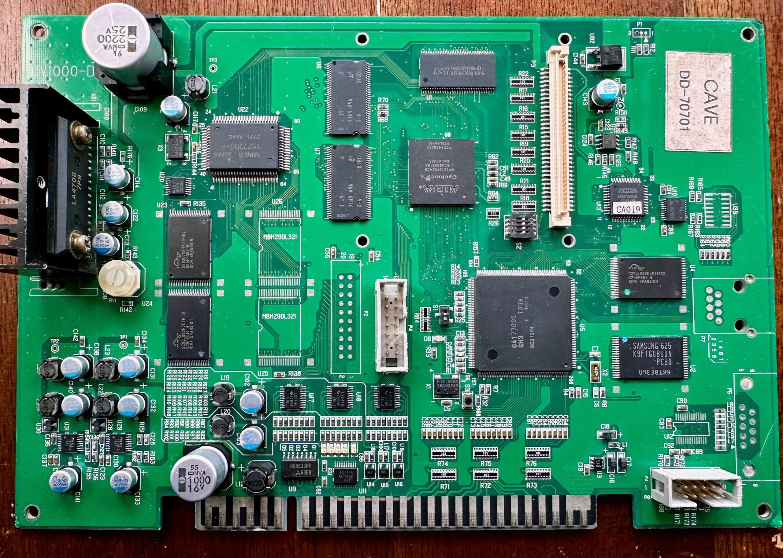
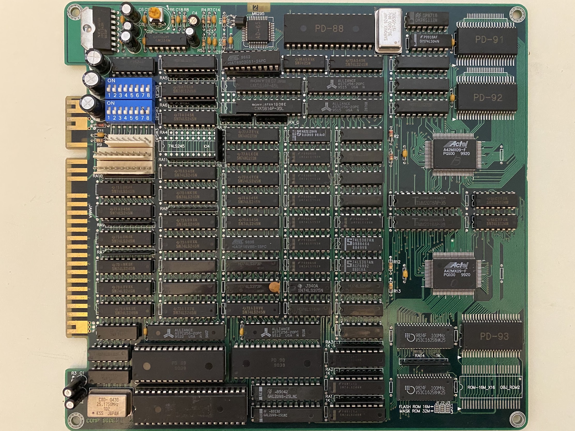
Single Board Variants
In some regions, Seibu Kaihatsu released some of their games on cost-reduced, all-in-one single boards. These boards are “locked” to the game they ship with, do not have stereo output available, and in some cases use lower-quality dual OKI MSM6295 ICs for audio instead of the Yamaha YM271-F IC that the two-board SPI platform utilized.
- SYS386I -Raiden Fighters 2 Operation Hell Dive 2000 (AMD 386 CPU and dual OKI MSM6295 Audio)
- SYS386F – E-Jan Sakurasou (Intel 386 CPU and Yamaha Audio)
- SYS386H – Raiden Fighters Jet 2000 (AMD 386 CPU and dual OKI MSM6295 Audio)
- SXX2F – E-Jan Sakurasou (Intel 386 CPU and Yamaha Audio)
- SXX2G – Raiden Fighters Jet (AMD 386 CPU and Yamaha Audio)
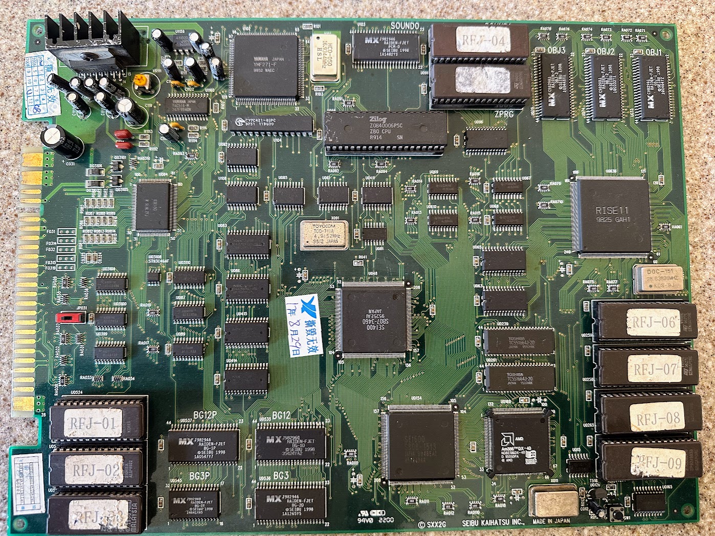
Photo Credit: ShootTheCore
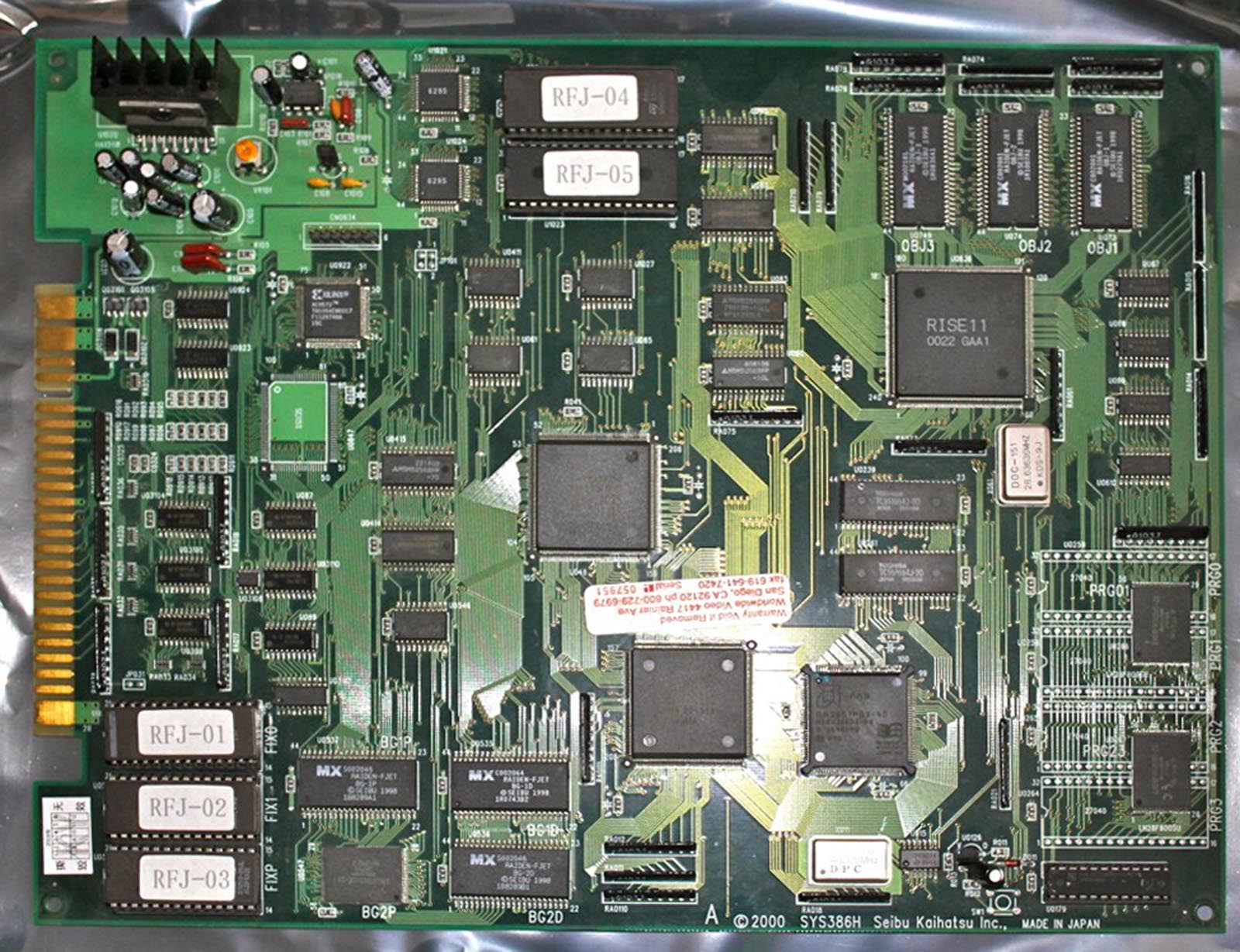
Photo Credit: RF Emporium
The SPI hardware and games was never bootlegged or cloned by another company.
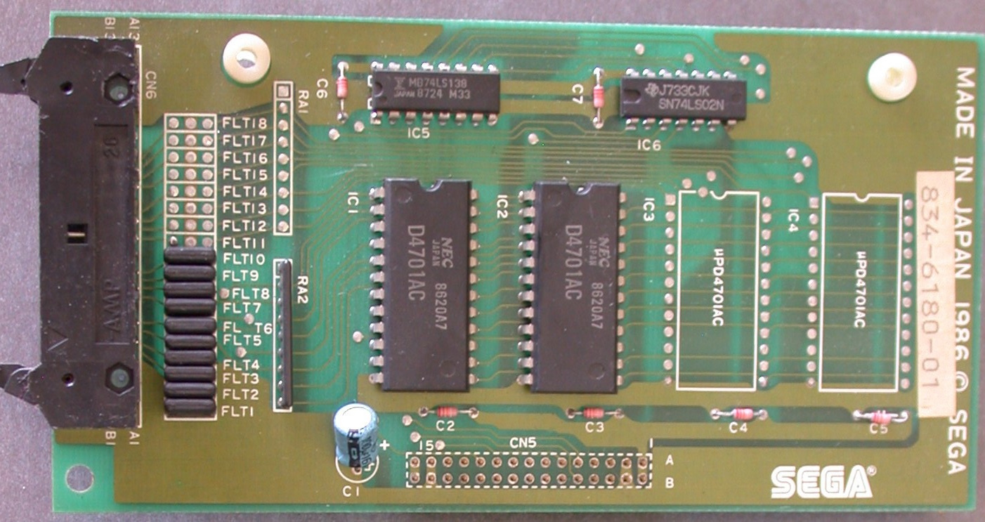
Daughterboards
The SPI platform only utilized one daughterboard – the SXX2C Mahjong adapter used with E-Jan Sakurasou.
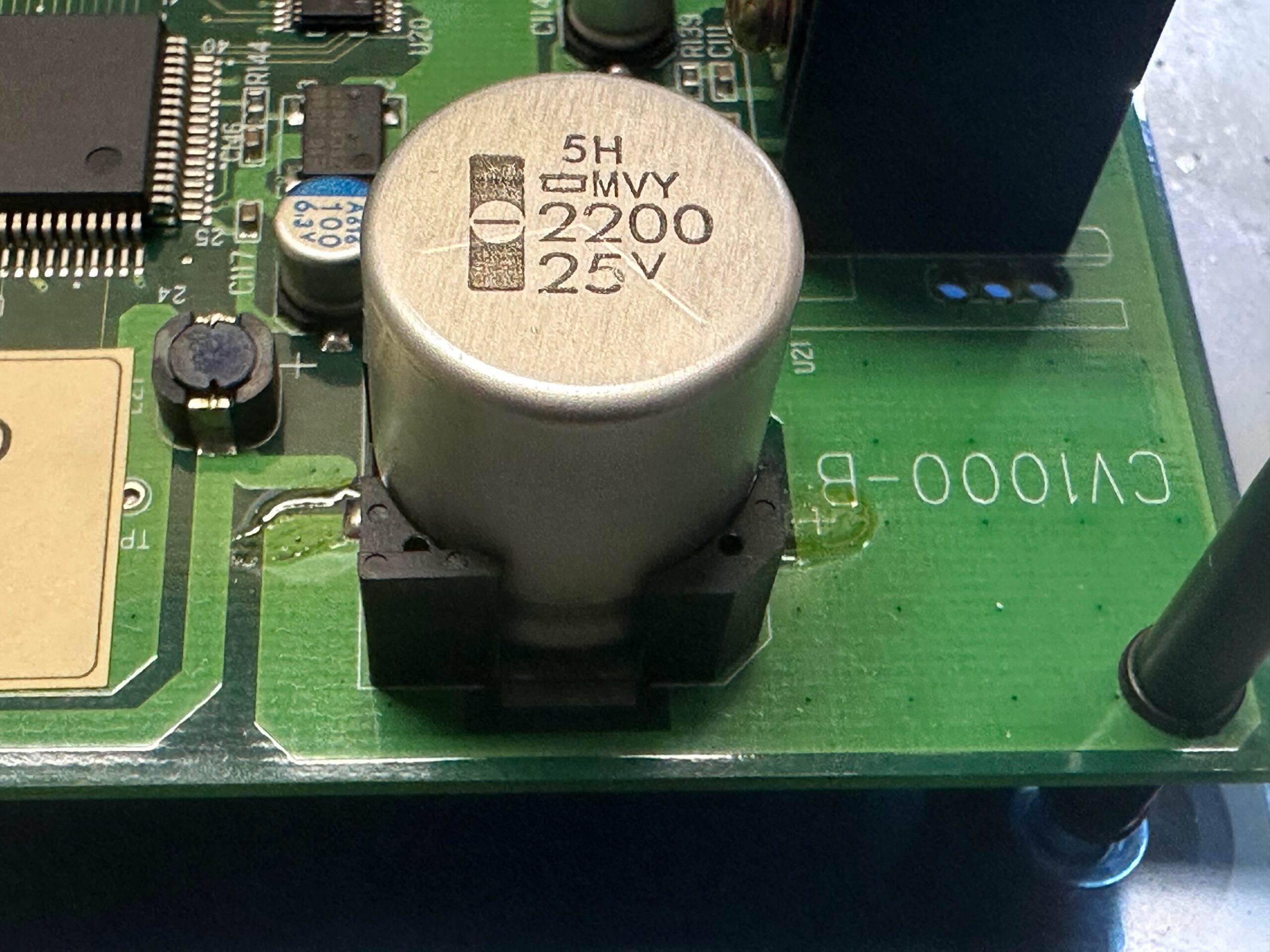
Capacitor List – V2.0 and V2.1 (credit: ekorz)
| Location | Capacitance | Voltage | Diameter (mm) |
| C123 | 470 uF | 26 V | 10 |
| C051 | 470 uF | 16 V | 10 |
| C012 | 10 uF | 16 V | 5 |
| C0911 | 10 uF | 16 V | 5 |
| C0921 | 10 uF | 16 V | 5 |
| C0926 | 10 uF | 16 V | 5 |
| C127 | 10 uF | 16 V | 5 |
| C1216 | 10 uF | 16 V | 5 |
| C121 | 10 uF | 16 V | 5 |
| C096 | 100 uF | 25 V | 6.3 |
| C129 | 100 uF | 16 V | 6.3 |
| C1210 | 100 uF | 16 V | 6.3 |
| C1214 | 100 uF | 16 V | 6.3 |
| C122 | 100 uF | 16 V | 6.3 |
| C1215 | 100 uF | 16 V | 6.3 |
| C124 | 100 uF | 16 V | 6.3 |
| C1217 | 100 uF | 16 V | 6.3 |
| C125 | 100 uF | 16 V | 6.3 |
| C1219 | 100 uF | 16 V | 6.3 |
Film / Ceramic Resistors – Optional
| Location | Capacitance | Lead spacing (mm) |
| C0920 | 182K | 5 |
| C0923 | 182K | 5 |
| C0927 | 392K | 5 |
| C008 | 392K | 5 |
| C0924 | 222K | 5 |
| C0913 | 222K | 5 |
ROM Details (credit: MAME, twistedsymphony)
Due to the variety of ROM boards used across the SPI games, consult the MAME Driver for game-specific ROM assignments.
The DIP EPROMs can be replaced with a 27C040 EPROM. Replacement of a faulty SMD Mask ROM with an SMD flash might be possible depending on which mask ROM it is.
Protection Mechanisms
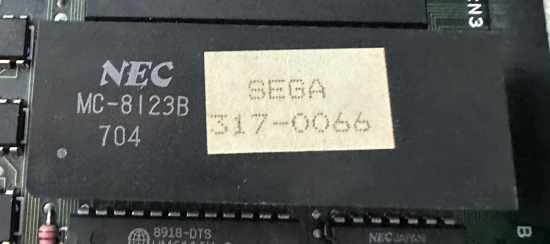
Sprite data is encrypted differently for each game and paired to a specific sprite data decryption IC on the cartridge board. This proved to be an effective deterrent against cartridge game conversions and bootlegging.
Schematics & Datasheets
Schematics for the SPI hardware are not available.
Additional Resources
| MAME SPI Driver | https://github.com/mamedev/mame/blob/master/src/mame/seibu/seibuspi.cpp |
| Trap15: SPI Revive | https://bitbucket.org/trap15/spi_revive/src/master/ |
| Ikotsu: Raiden Fighter Jet – Seibu SPI | http://ikotsu.blogspot.com/2010/01/raiden-fighter-jet-seibu-spi-jet.html |
| Everten SPI Stereo Board | https://shewfly.com/products/seibu-kaihatsu-spi-stereo-board-by-everten https://www.candycabclub.com/product/everten_spi |
| World of Arcades: Changing SPI region codes | http://www.world-of-arcades.net/seibu_spi/ |