Block Block repair log

 PCB Repair Logs, Repair Logs  Comments Off on Block Block repair log
Aug 282011
 

Had this board for ages and never bothered with it.
A guy recently asked me to check out the PAL dumps for Block Block but due to my board being broken Ive never been able to test so I thought id try and repair mine.

As you can see, the board looks a state
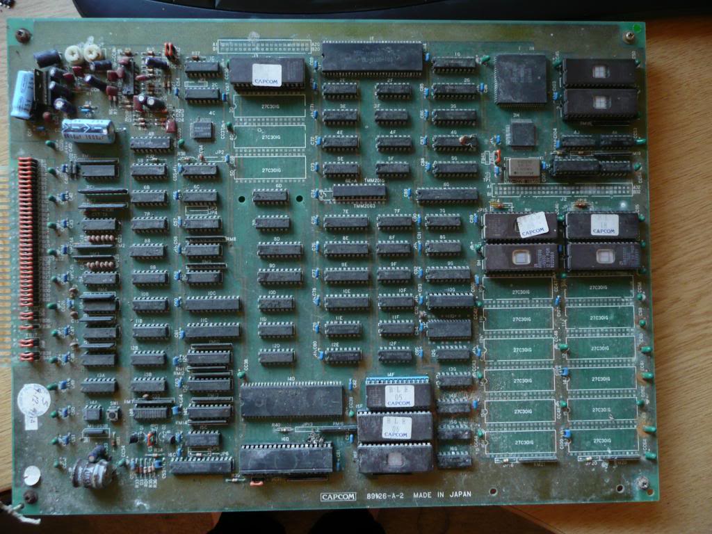
There is a suicide battery on these boards that is certainly dead. I removed this and went over to The Dead Battery Society and downloaded the desuicided ROMs.
After burning the two 27c020’s and a 27c512 and following the guide steps I got nothing but a black screen.
I removed the Kabuki CPU and replaced it with a standard Z80.
Now I get the RAM tests and they all pass OK then goes to a blank screen.

After a bit of head stratching I relised that the 27c020 is JEDEC compliant yet the 27c301’s that the board expects are not.
Time for a bit of modding.

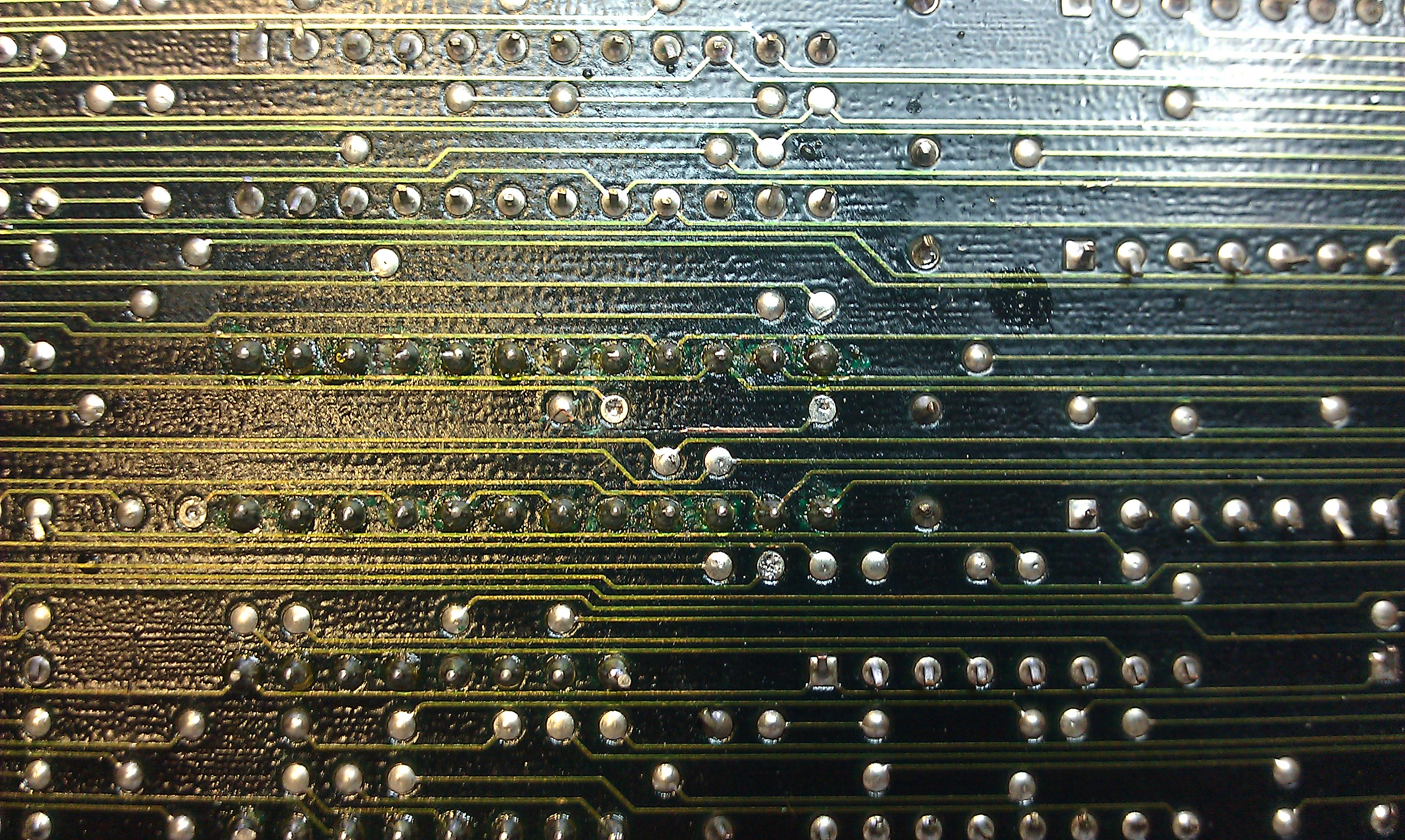
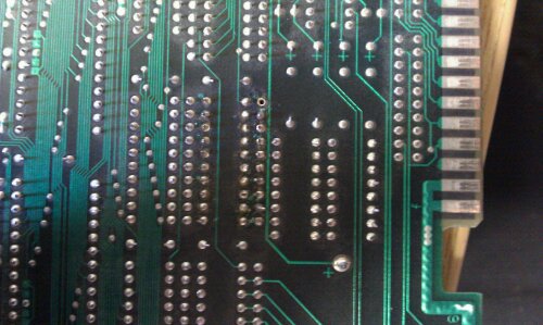
I lifted pins 2, 24 and 30 on both 020’s and pins 1 and 22 on the 27c512.
I ran a link from pin 21 of the Z80 pin 24 of both 020’s and pin 22 of the 512. This is the /OE line.
I ran a link from pin 60 of the DL-020F-108U custom IC to pin 2 of both 020’s. This is the A16 line.
Link pin 30 from both 020’s to pin 1 of the 512 then link them all to pin 27 of the Z80 CPU. This is the A17 line.

That should not be complete and the game should boot.
I was able to test both the PAL dumps I have made now and they both work.

There is no sound on my board and it looks as though most of the sound circuit is rotton so wont be trying to repair that. Its a nice game but I have no interest in it at all.
 Posted by at 11:27 am

Silent Scope repair log

 PCB Repair Logs, Repair Logs  Comments Off on Silent Scope repair log
Jul 112011
 

Bought a Silent Scope PCB recently.
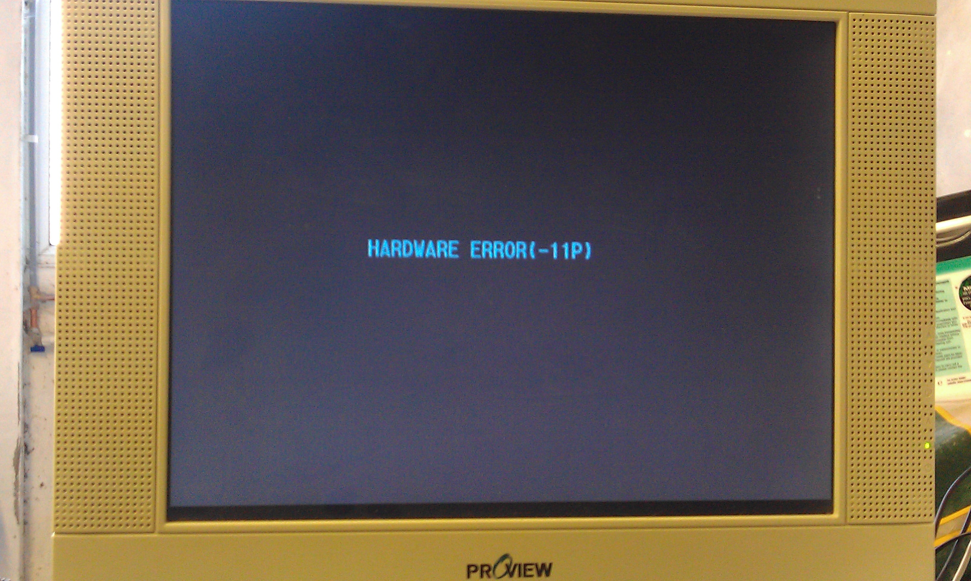
It had the “Hardware Error 11P” fault which is known to be cause by the battery failing in the TimeKeeper RAM.
Since the contents of these RAMs are in MAME I thought id fix one up which was probably a stupid idea as I dont have the setup to actually use it, but at least I know I can fix these now.

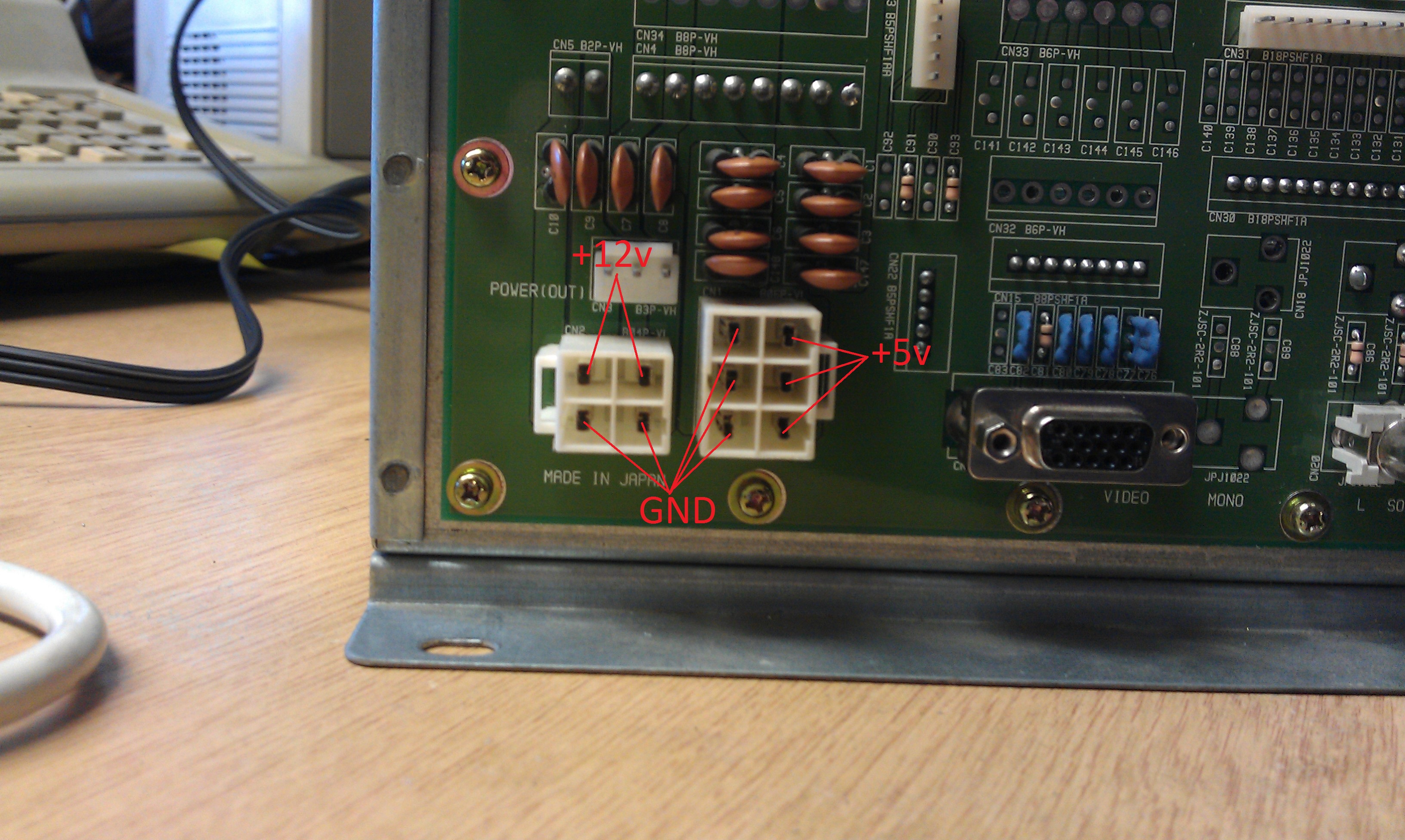
To get this thing booted up I modified my ATX power supply that I had previously modded to run my NAOMI setup. The power connection are labelled in the picture.

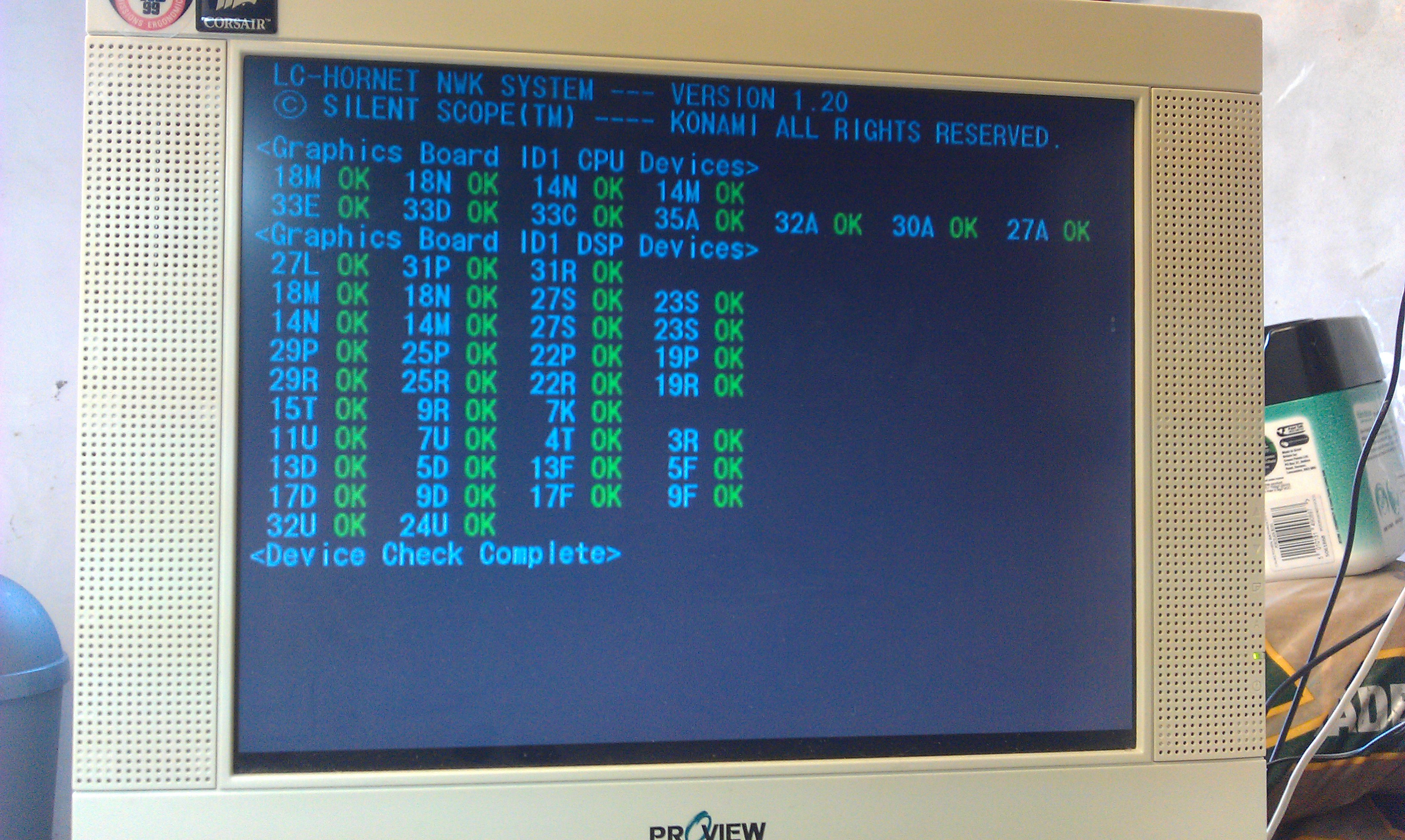
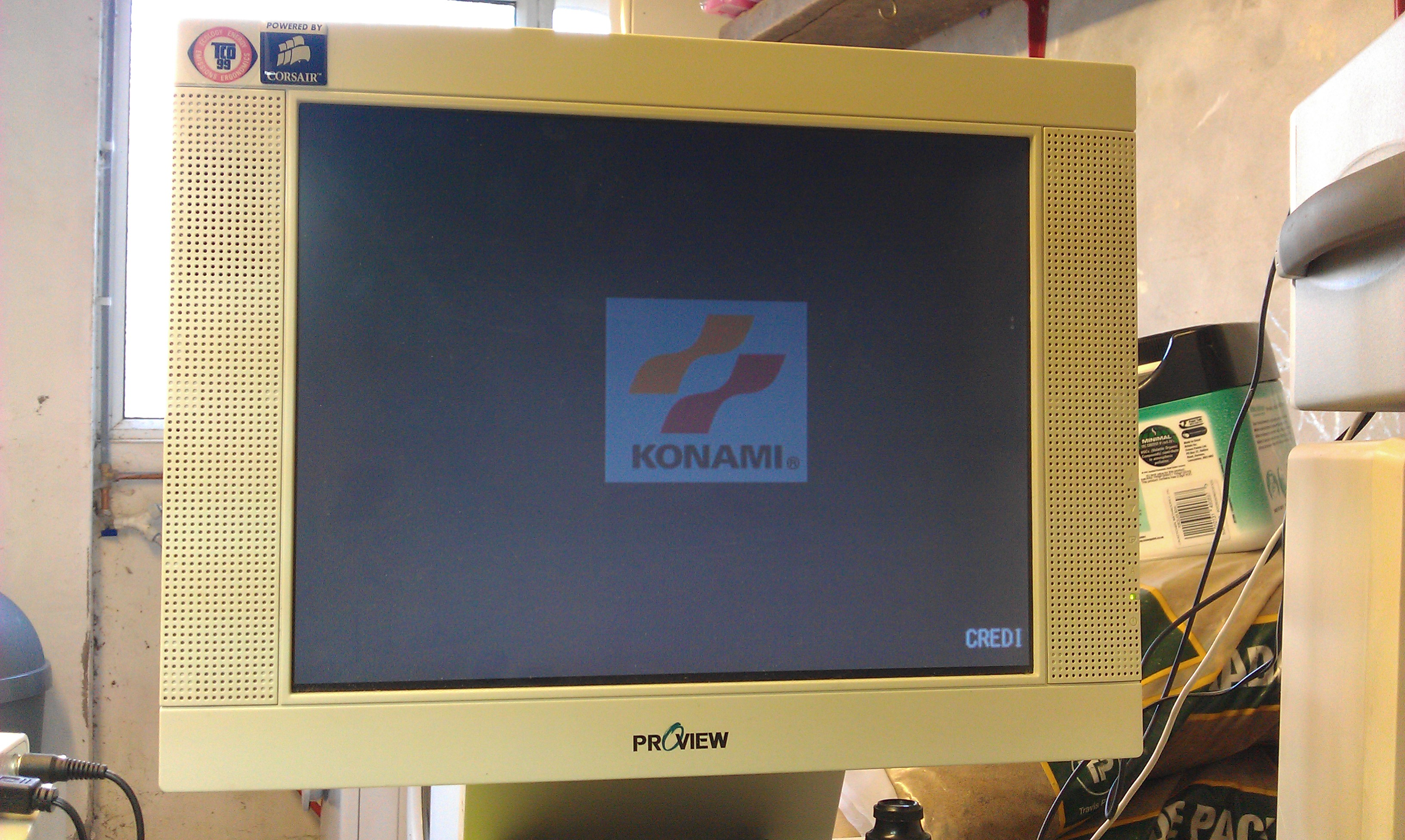
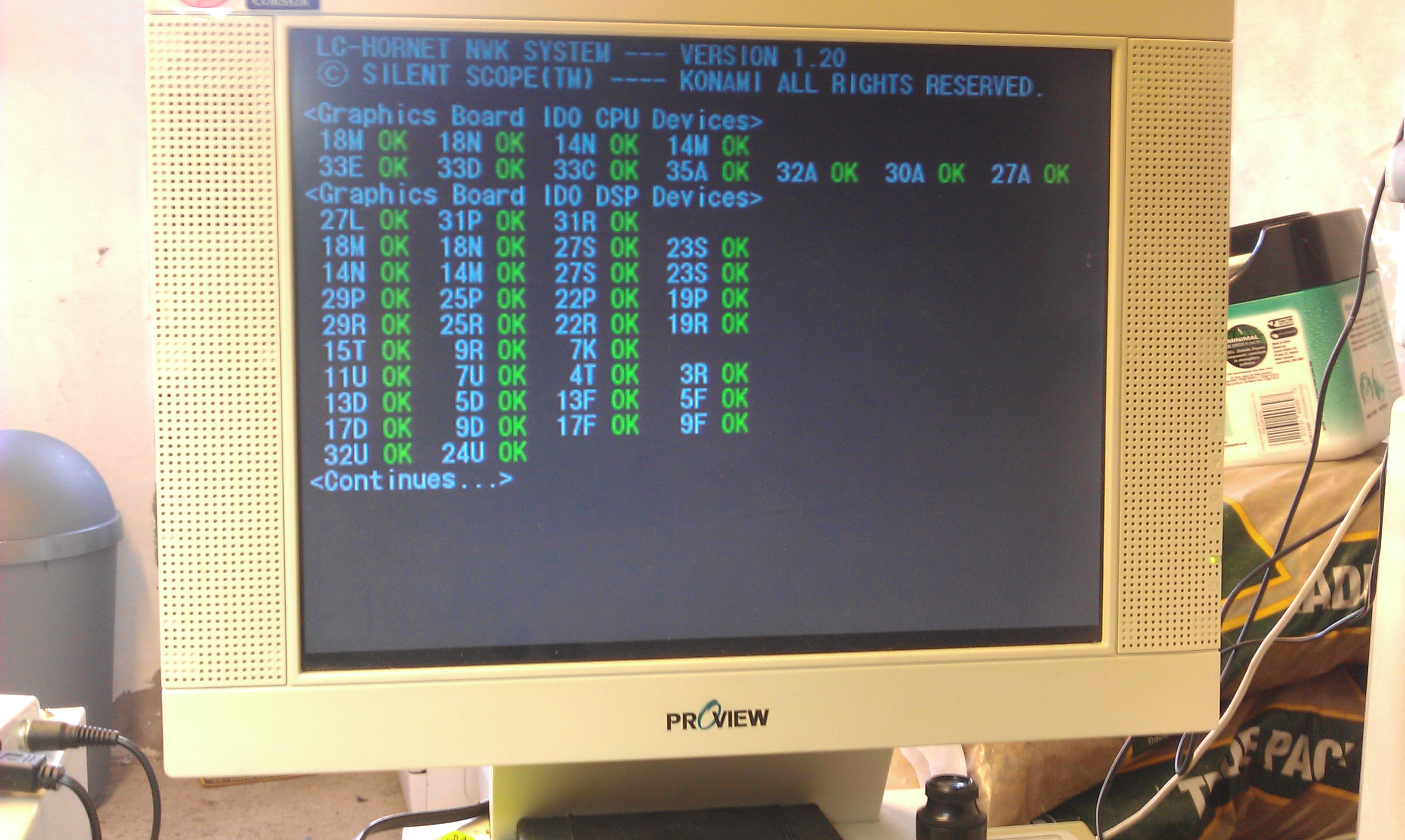
I had to run the VGA output through a standards converter too, it must be 31kHz. Once it was all fired up I was greeted to the startup procedure which consists of what look like RAM/ROM checks. All these passed but then it just hangs on the fault screen for a bit then resets.


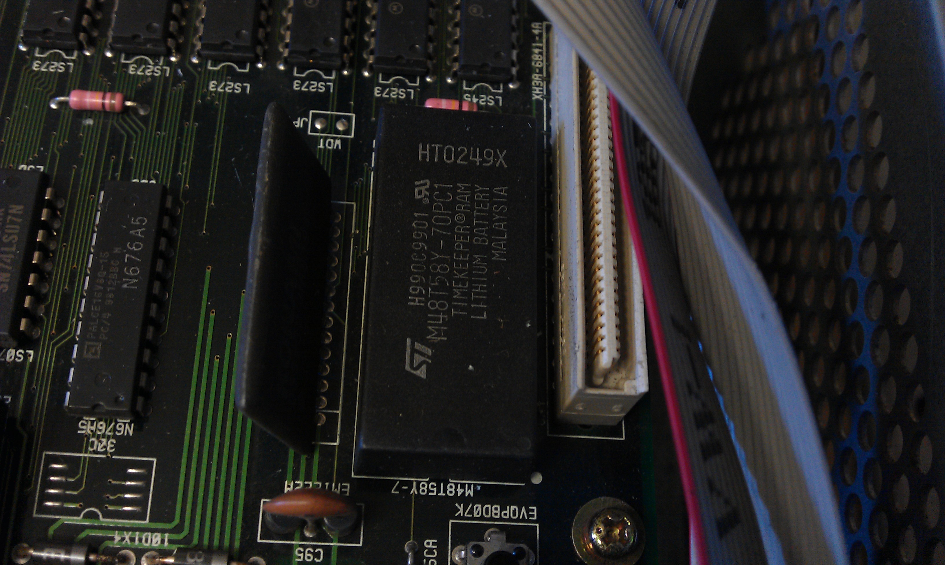
The TimeKeeper RAM is located on the top board of a 3 board stack.

I removed the board and set to work desoldering the old RAM chip. It went smoothly considering it had the signature Konami thin traces and small through holes, the RAM just dropped out.

Thought it best to fit a socket in case of any problems with it in the future.
As this version shows up as v1.20, the RAM dump needed if from set UAB.
I did try reprogramming the original but it didn’t hold the data.
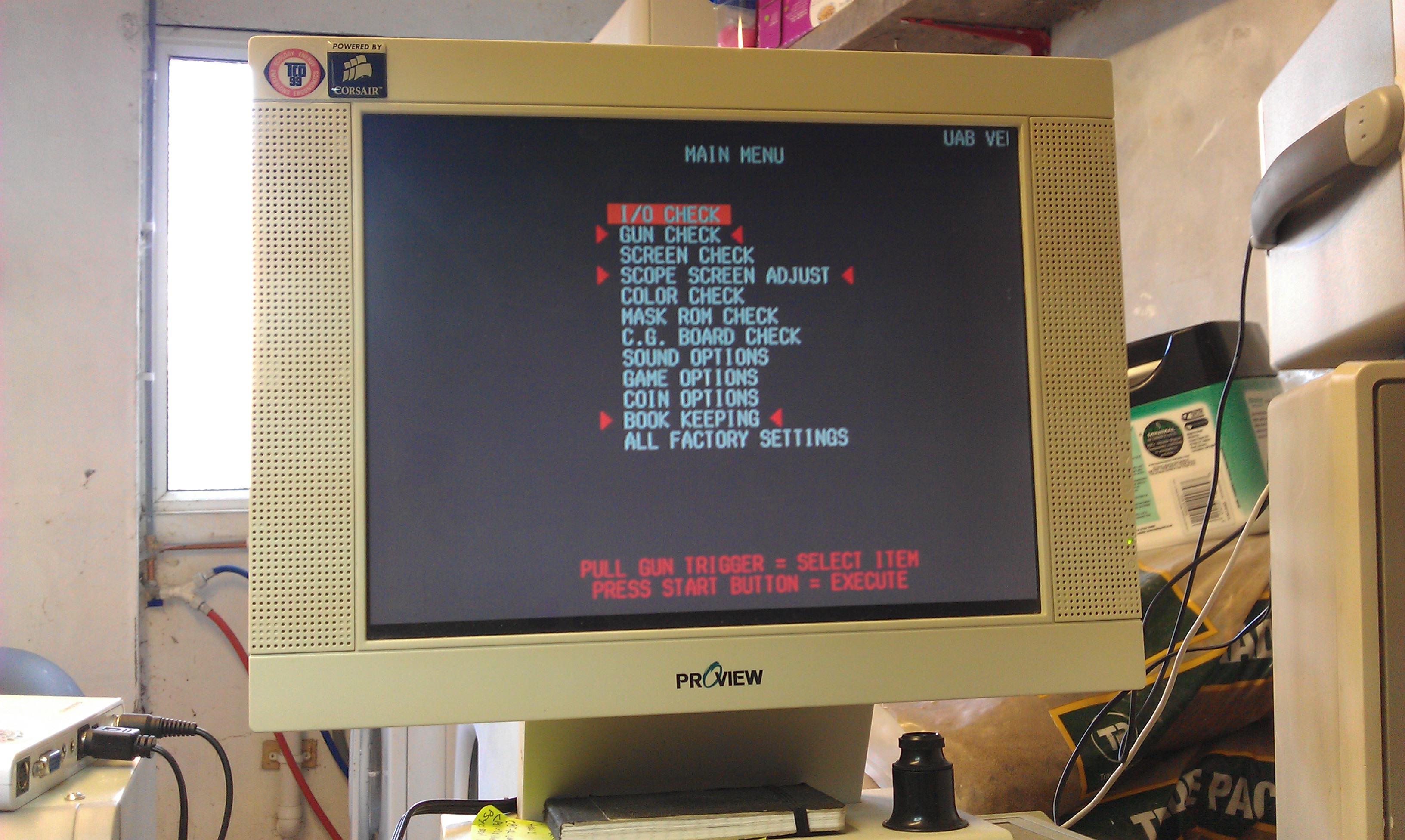
After fitting the new RAM the game booted to the test menu.


After working my way through the menus using the pins on the I/O board I was able to finally fire the game up.


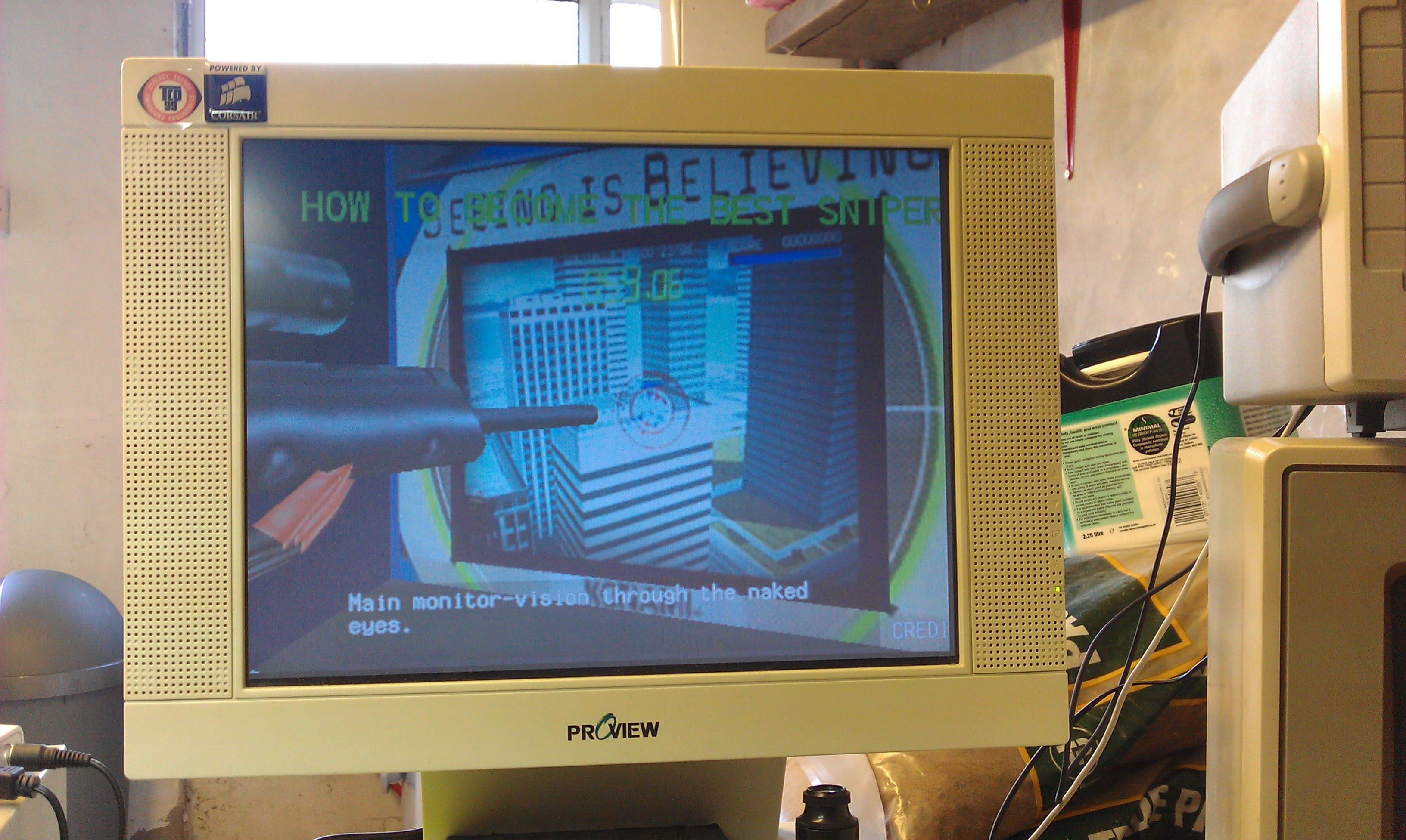
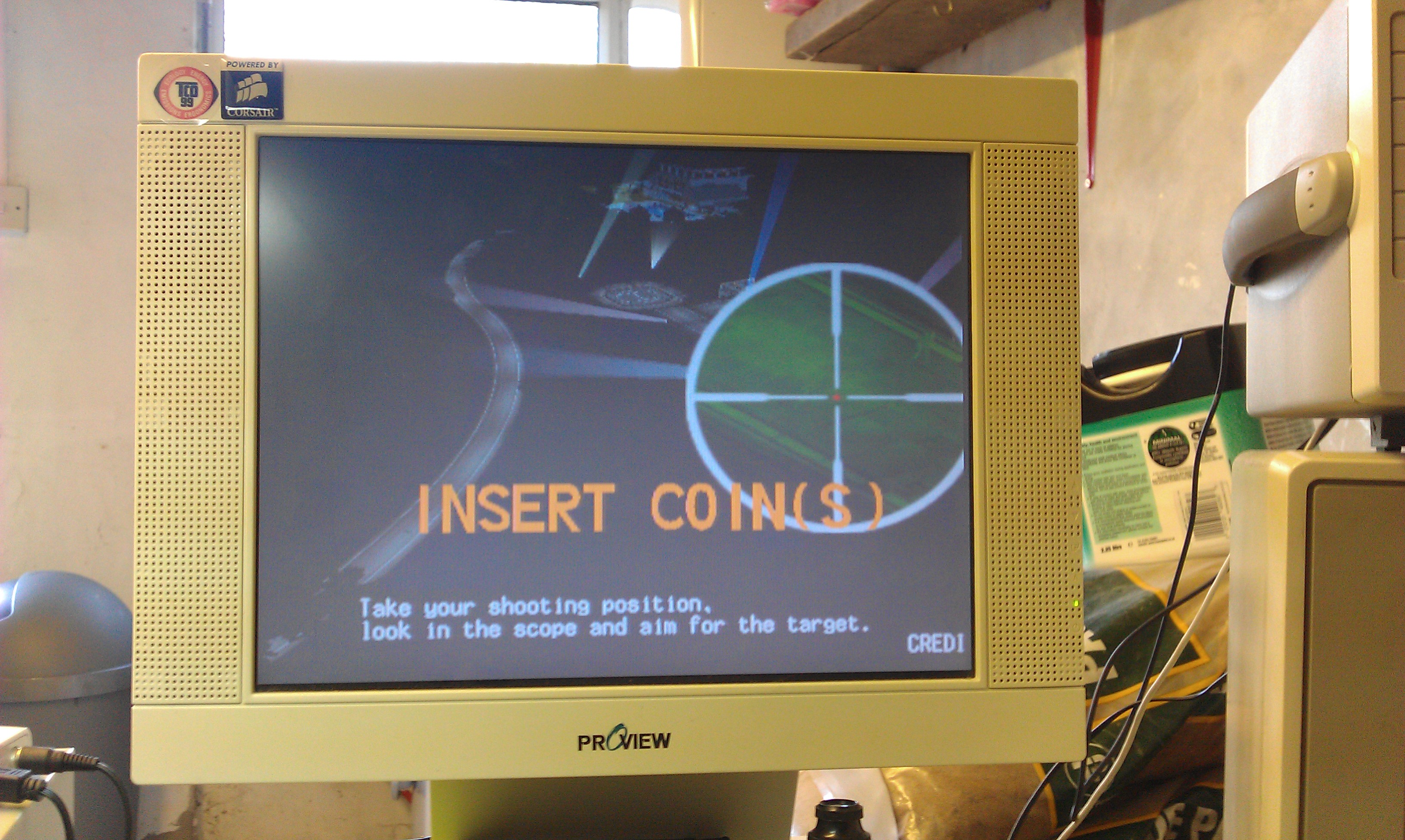
So, I have verified that the sound works, the game boots and the digital inputs are working. I have no reason to believe that the rifle wouldn’t work if connected.

UPDATE (06/07/2015):
If you have an Arduino and fancy testing out my Timekeeper programmer ‘sketch’ then you can download it from the Downloads section.
It worked for me but I make no promises it will work for you. Its a basic proof of concept and could do with being developed.

Robocop repair log #1

 PCB Repair Logs, Repair Logs  Comments Off on Robocop repair log #1
Jun 152011
 

Bought a Robocop board from the AO forums. Seller says the jump button didn’t work.
Doing a visual inspection revealed a burnt out track just off pin 23 on the edge connector, which is button 2, in this case, the jump button.

image

I repaired the trace but still no joy with getting the controls back.
Further inspection showed that the custom resistor array had burnt out. This resistor array has some modified characteristics compared a normal array, it passes an input out to a different pin and has a few other differences too. As I don’t have any spares of the custom array I decided to use a standard one pulled from a scrap board.

image

To make this work I had to short pins 6 and 7 together and 8 and 9 together. These are for button 1 and button 2.
The board is now fully working but ill keep an eye out for an original replacement part to fit.

Rastan repair log #1

 PCB Repair Logs, Repair Logs  Comments Off on Rastan repair log #1
May 022011
 

Very nearly gave up with this one thinking it was a custom IC fault, glad I never.

Was sold this board as a non worker, the guy said it boots to a white screen and the CPU needed to be looked at.
He was right on both counts.

image
image

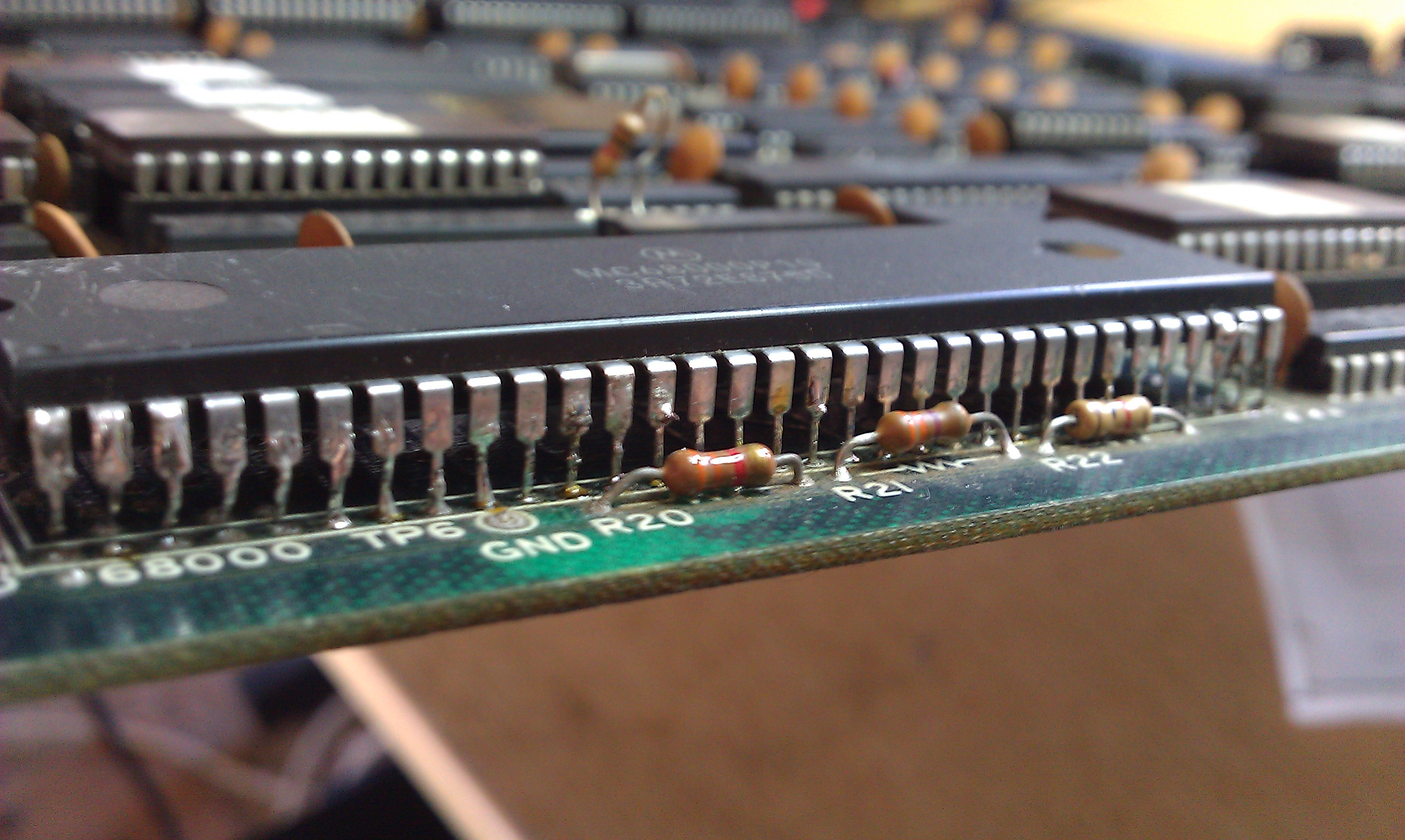
Before I did anything that CPU needed socketed. Once I had done that I fired the board up again but got the same white screen. I checked the data lines of the CPU and they were dead. I initially tried a known good 68000 CPU but this resulted in the same screen.
There are 6 ROMs next to the CPU which are the program ROMs. I pulled all these and checked them against MAME. The first 3 checked were fine the last 3 were actually from an Operation Wolf board and 2 of those were dead anyway. Burned 3 replacement 27c512 EPROMs and tested again.
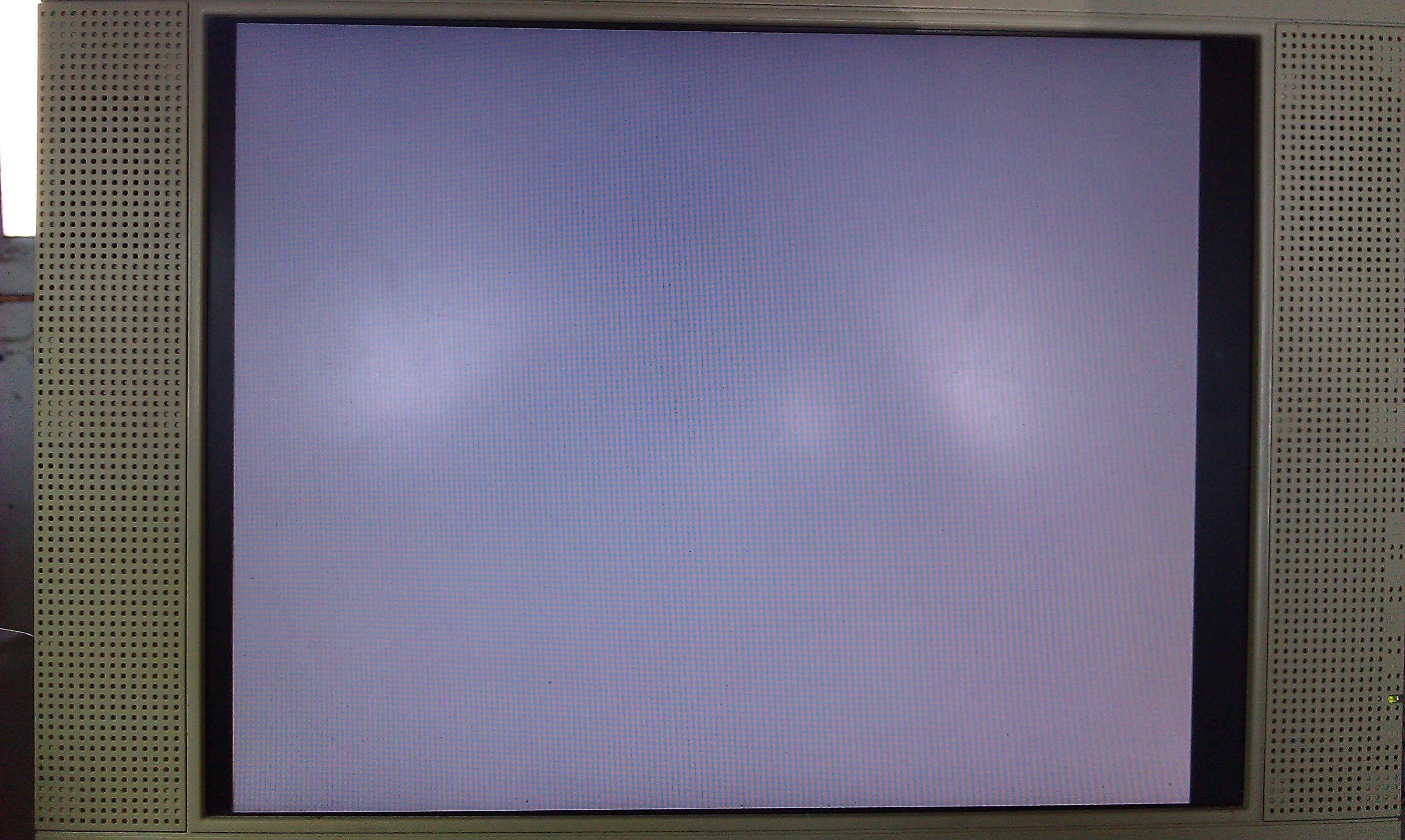
This time I got a white screen with some garbage on.
After this I plugged in the Fluke 9010 and ran some ROM and RAM tests. The ROMs passed fine but one of the RAMs had failed. The TMM2063 @ IC10 was shot, I used a D4364 as replacement as its the first one I found compatible on a scrap board.
Board still booted with garbage.

image

All lines on the CPU had frozen.
Checking the game running in MAME I could see that when you first boot the game the whole screen flashes white for a second then the game boots.
I checked the 3 Interrupt line, IP0, 1 and 2, and found that IPL1 was dead, this came from a nearby PAL @ IC36. The PAL was giving an output so I ran a jumper wire to the CPU and booted again.
This time I got a full white screen with the Hi Score at the top and the game ran but only showing the sprite data.

image
image

I checked all the ROMs that hold the background data and they all checked out fine. These are MASKROMs and can be read as either 27c301 or a couple of reads as 27c512 with a small modification.
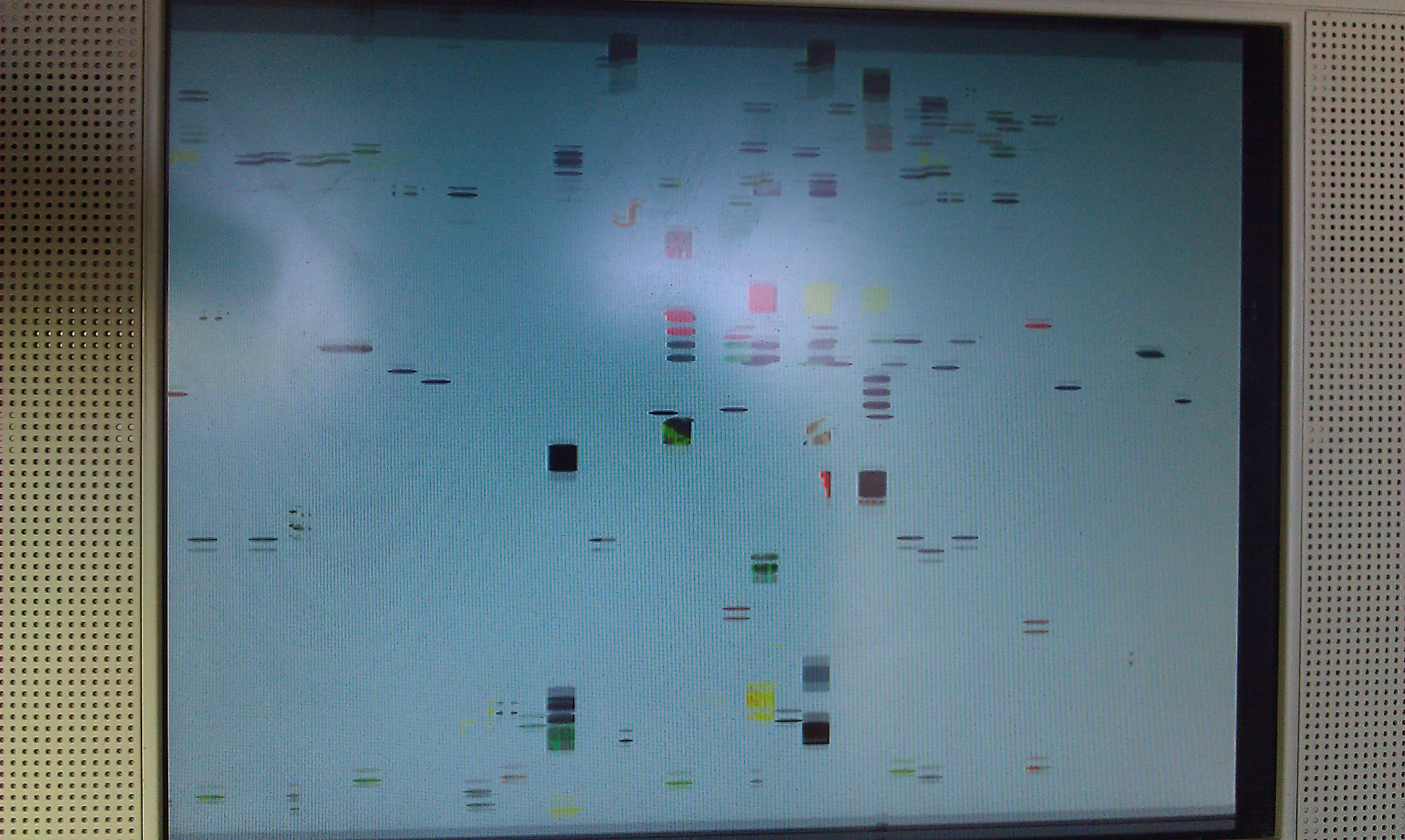
Following the data route from these ROMs I eventually came to a 74LS157 @ IC72. It had dead pins at #3 and #11. Pin 3 should go straight to +5v and pin 11 should come from address bus A10. Ran a couple of jumpers for these and got something a little different, the screen was still mainly white but I could see text underneath it and the sprite colours were now messed up.

image
image

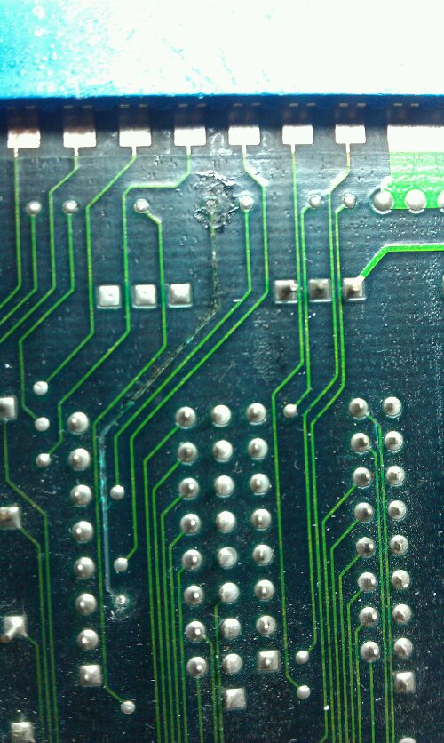
Looking underneath the board I found a discoloured track, when I ran the screwdriver over it, it came away from the board looking a little charred.

image

Only a short jumper required but it was underneath the palette RAM. I started checking the palette RAM and found pin 16 was dead. I removed this 2018 RAM @ IC73 and it tested faulty, replacing this with a 6116 brought the graphics back fully.

Mortal Kombat repair log

 PCB Repair Logs, Repair Logs  Comments Off on Mortal Kombat repair log
Apr 292011
 

Simple repair.
The controls were erratic. Using the input test in the diagnostic menu I could see 3 buttons and the right direction were being activated together.
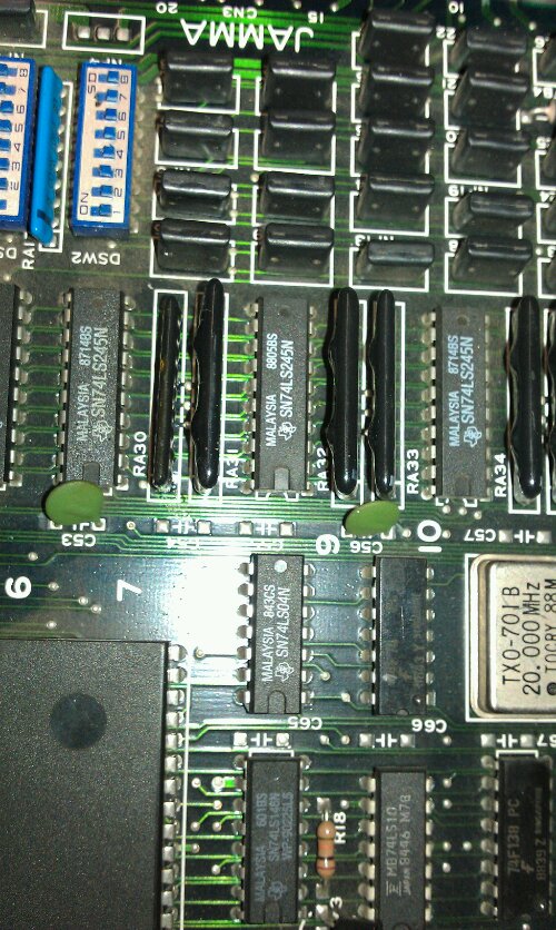
A visual inspection quickly pinpointed the fault. One of the input resistor banks was partially desoldered and cracked.

Trying to remove the IC myself proved quite a task but removed the two parts and slotted in a 4.7k resistor array from a scrap board. Now the inputs work fine.
Just need to find a sound board for it now.