Mar 242012
 

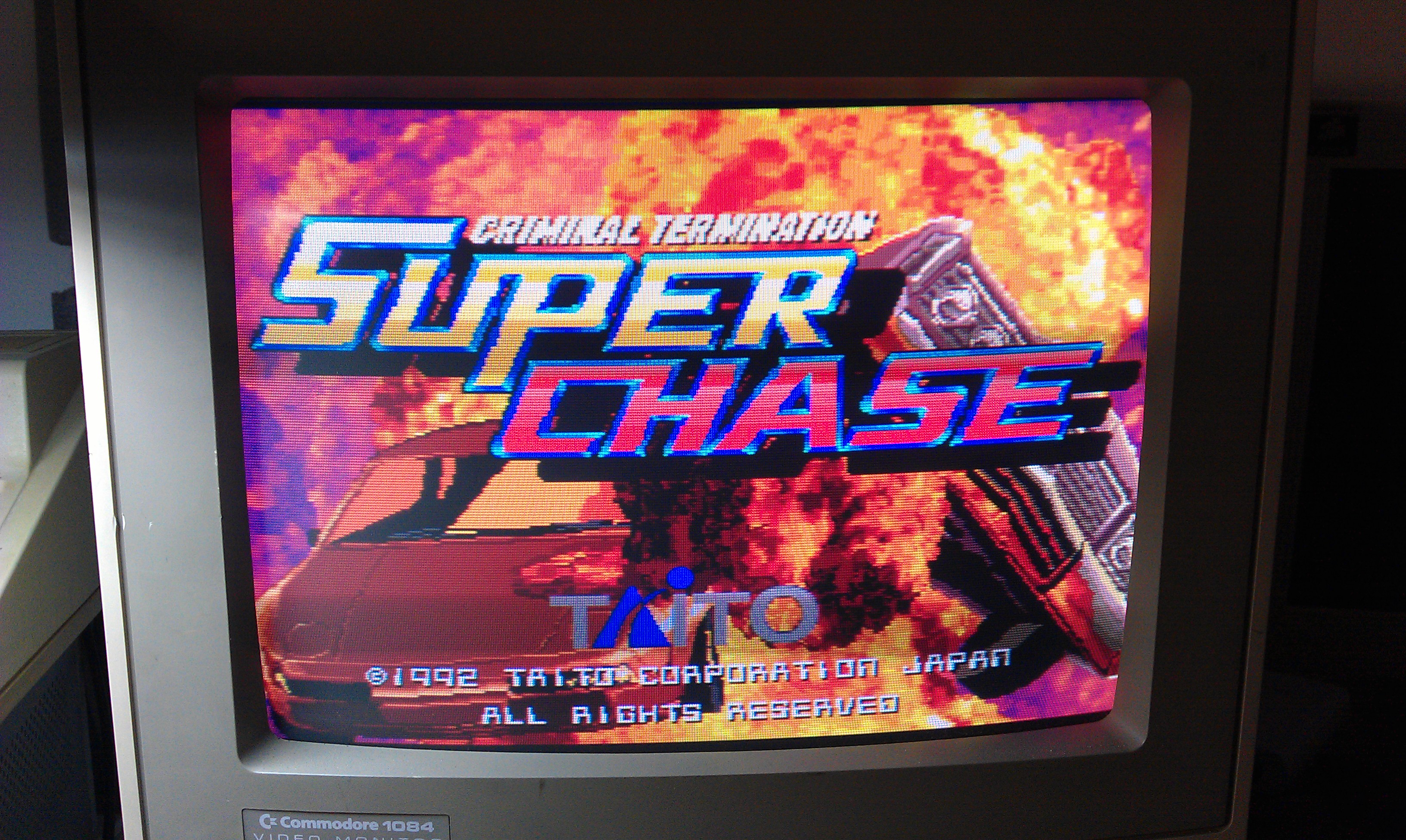
Been after a genuine board of this for a bit now and this one came along. I thought it might be in full working order but once again eBay lets me down.
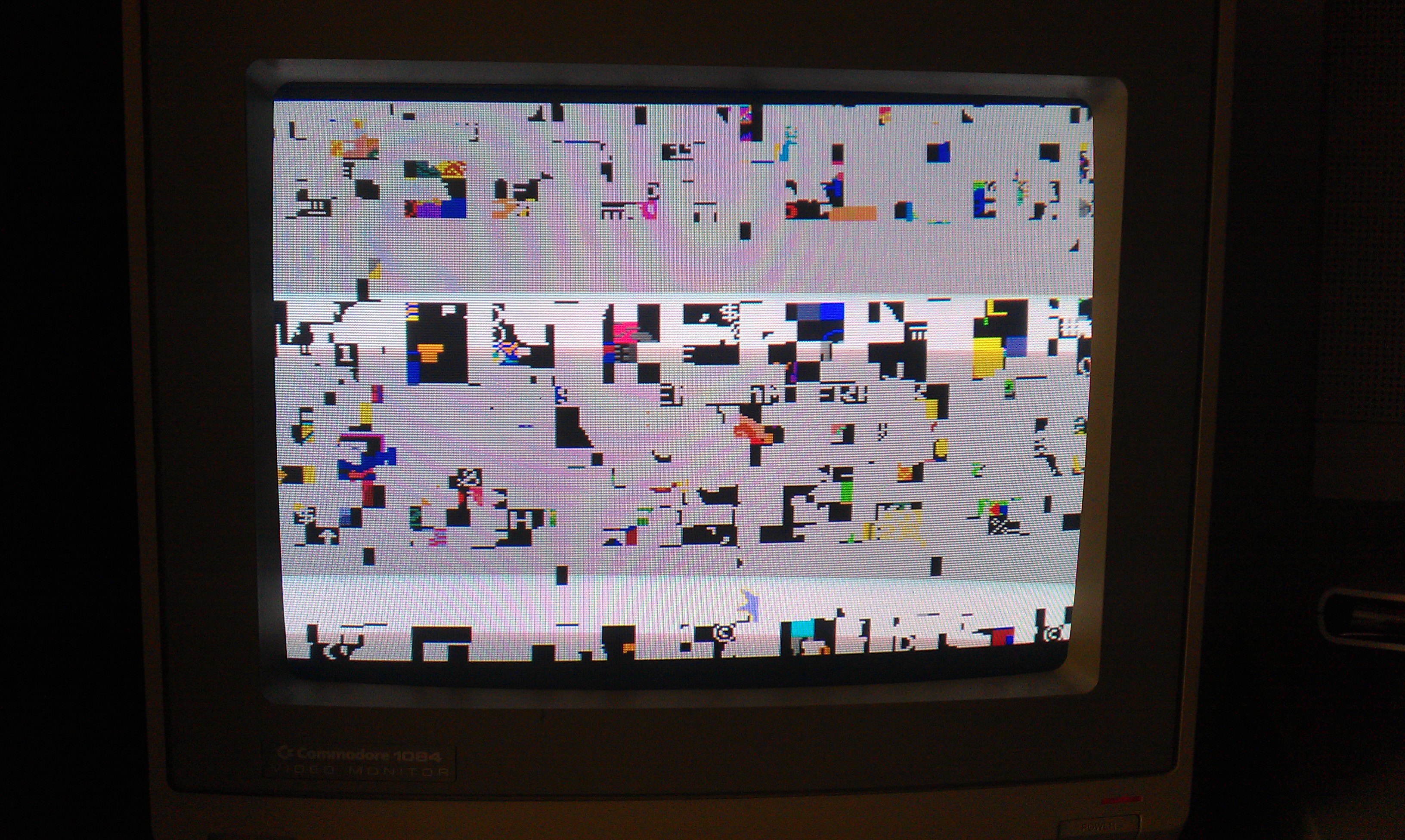
This one had jailbars through all the main sprites.

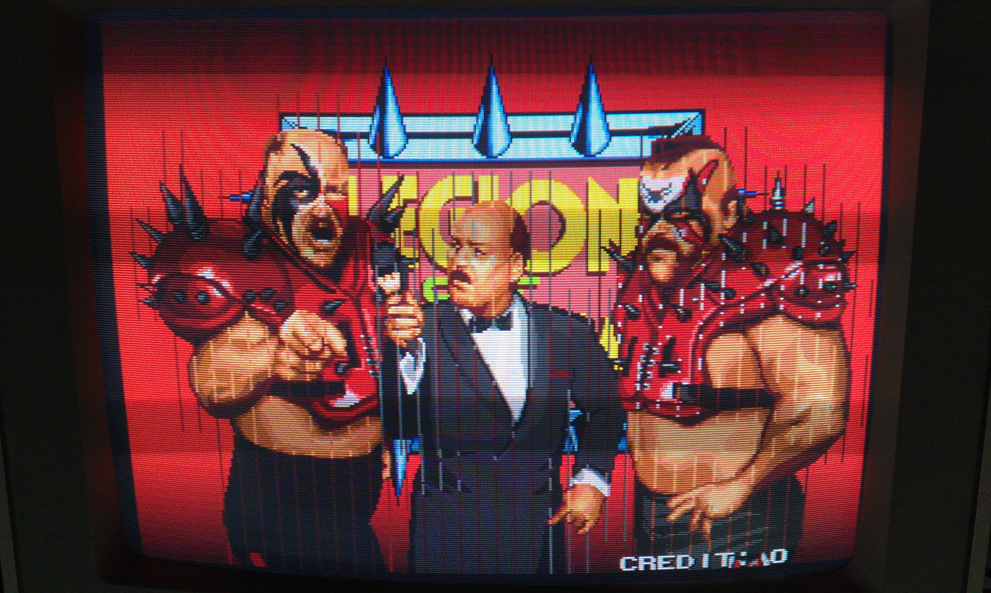
More often than not this is a bad ROM and this was ended up being just that.

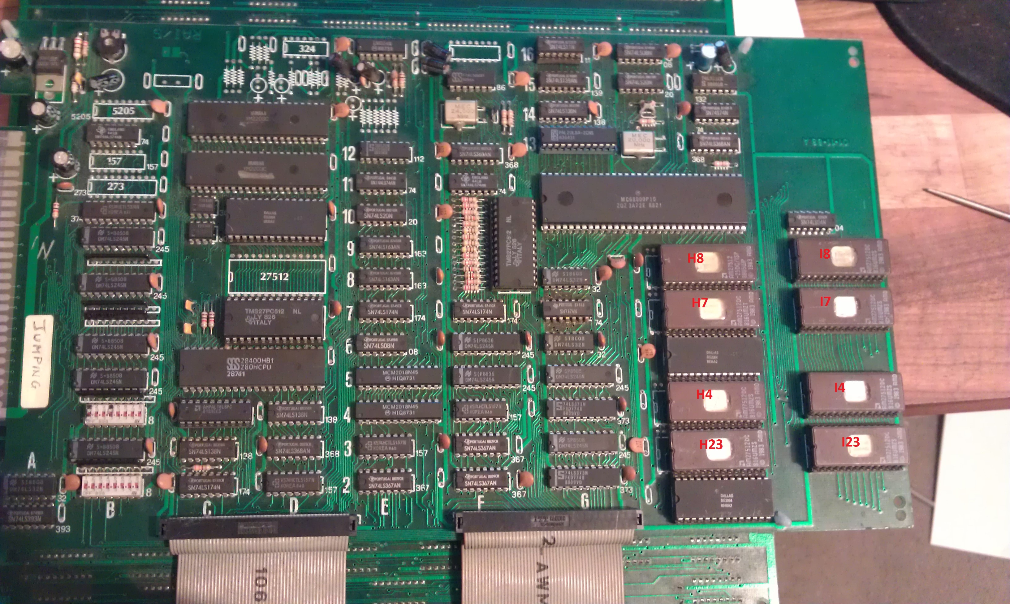
In the corner of this board there is a bank of 8 MASKROMs that contain the graphics. Unfortunately none of these are in sockets and as I couldn’t really see anything hugely wrong on the scope.
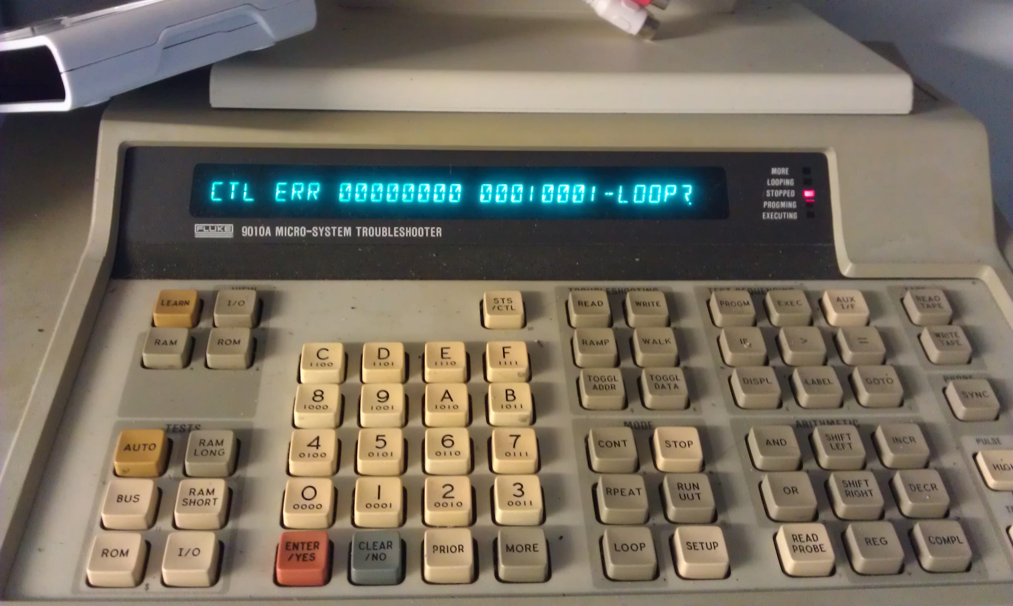
This game doesn’t have a test mode nor does it carry out any RAM/ROM tests on start up so I wrote a little self test program myself in assembly that tested the sprite RAM at location 0x0c2000 – 0x0c3fff in the address map and simply would display a “P” for a pass or “F” for a fail.
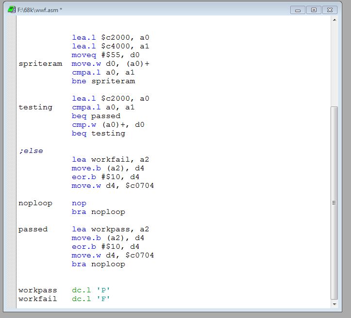

This passed no problem so my hope is for one of the ROM’s to be dodgy as opposed to one of those custom chips.
I set about desoldering them one at a time and checking along the way. After the fourth one I found my problem with a bad ROM dump.
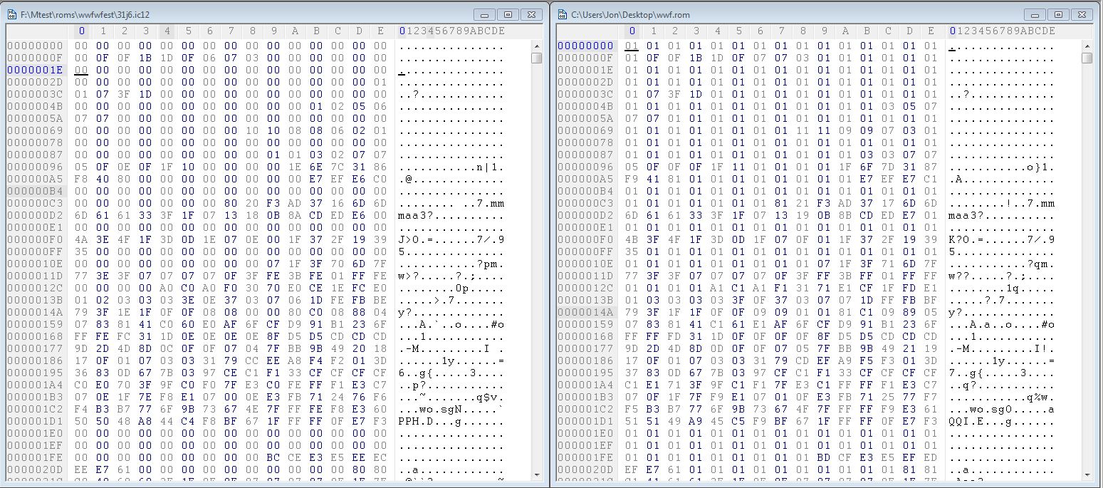
My dump is on the right and the MAME set dump is on the left. As you can see, bit 0 is stuck on.
I fitted a socket and reinstalled the ROM but with data line D0 lifted and checked it out with the scope.
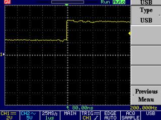
On a closer inspection it shows that the logic level isnt dropping below 2v.
The MASKROMs are pin compatible with 27C080 EPROMs of which I have none. I have ordered some so will hopefully receive it early next week

EDIT: EPROM came today, the game is now fully working
 Posted by at 5:41 pm

Jumping repair log #2

 PCB Repair Logs, Repair Logs  Comments Off on Jumping repair log #2
Mar 042012
 

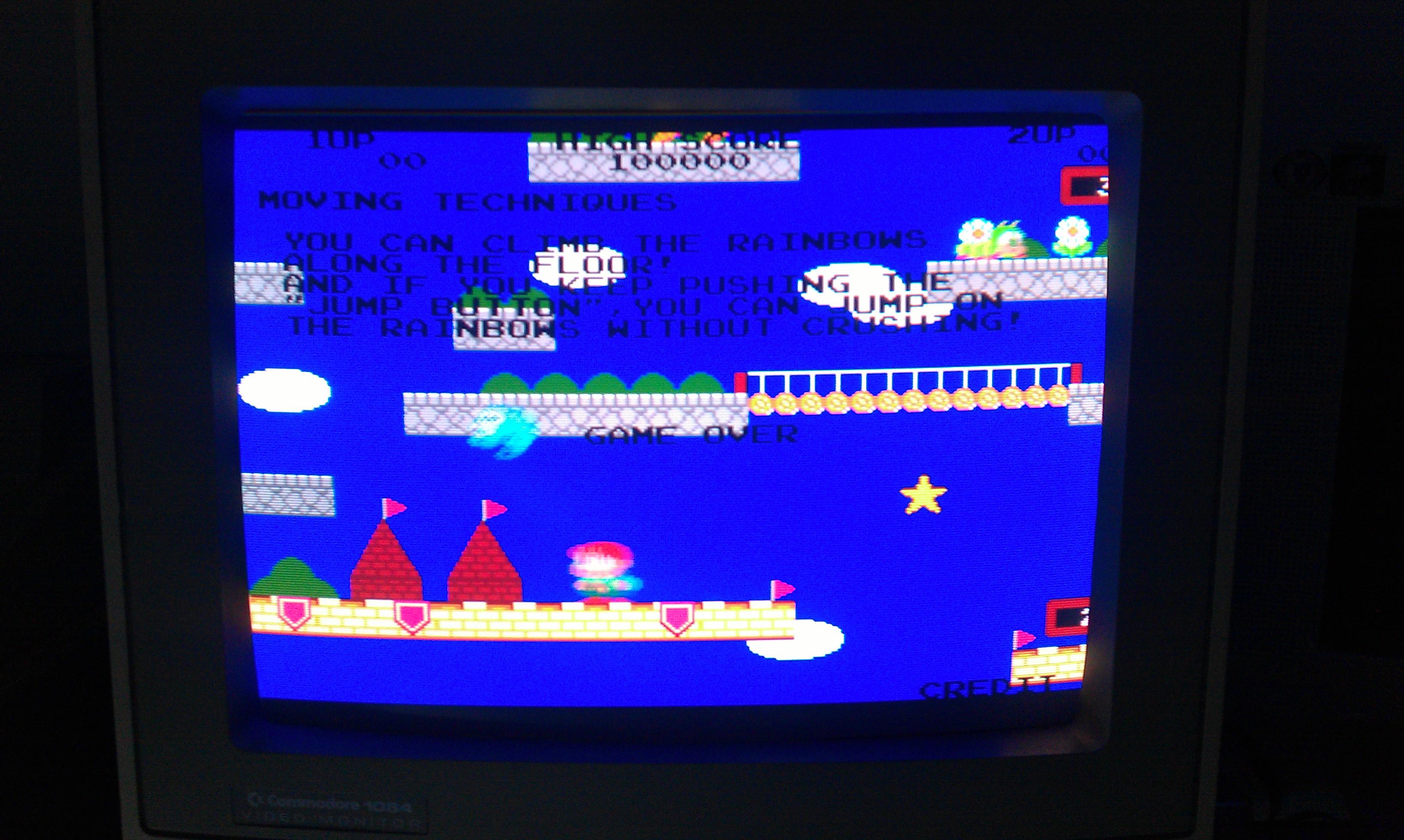
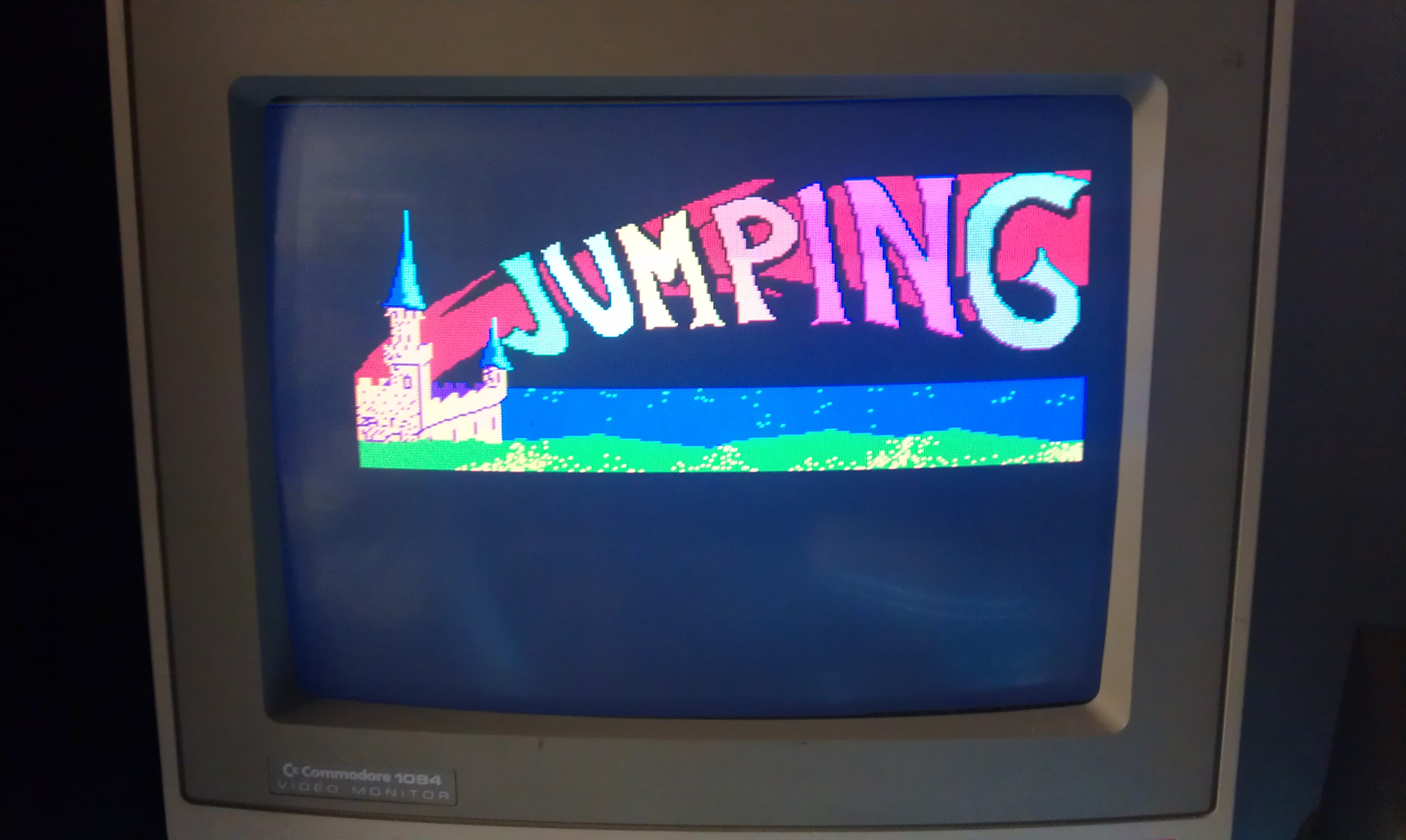
As mentioned in a previous post, when I converted my Jumping board to Rainbow Islands I noticed that all the text in game was black. Going back through some pictures I took when I first got the board I see its present there too.

So where do I start?
I know from making my conversion that the palette values are stored in the program ROMs and they are pushed out to the palette RAM at address 200000.
I looked at the RAM with a scope and all seemed fine plus all the other colours seemed fine.
I also know that all the values required for this text colour is when the 2 least significant bits (A0 and A1) are active, so I traced these out down to the video board.

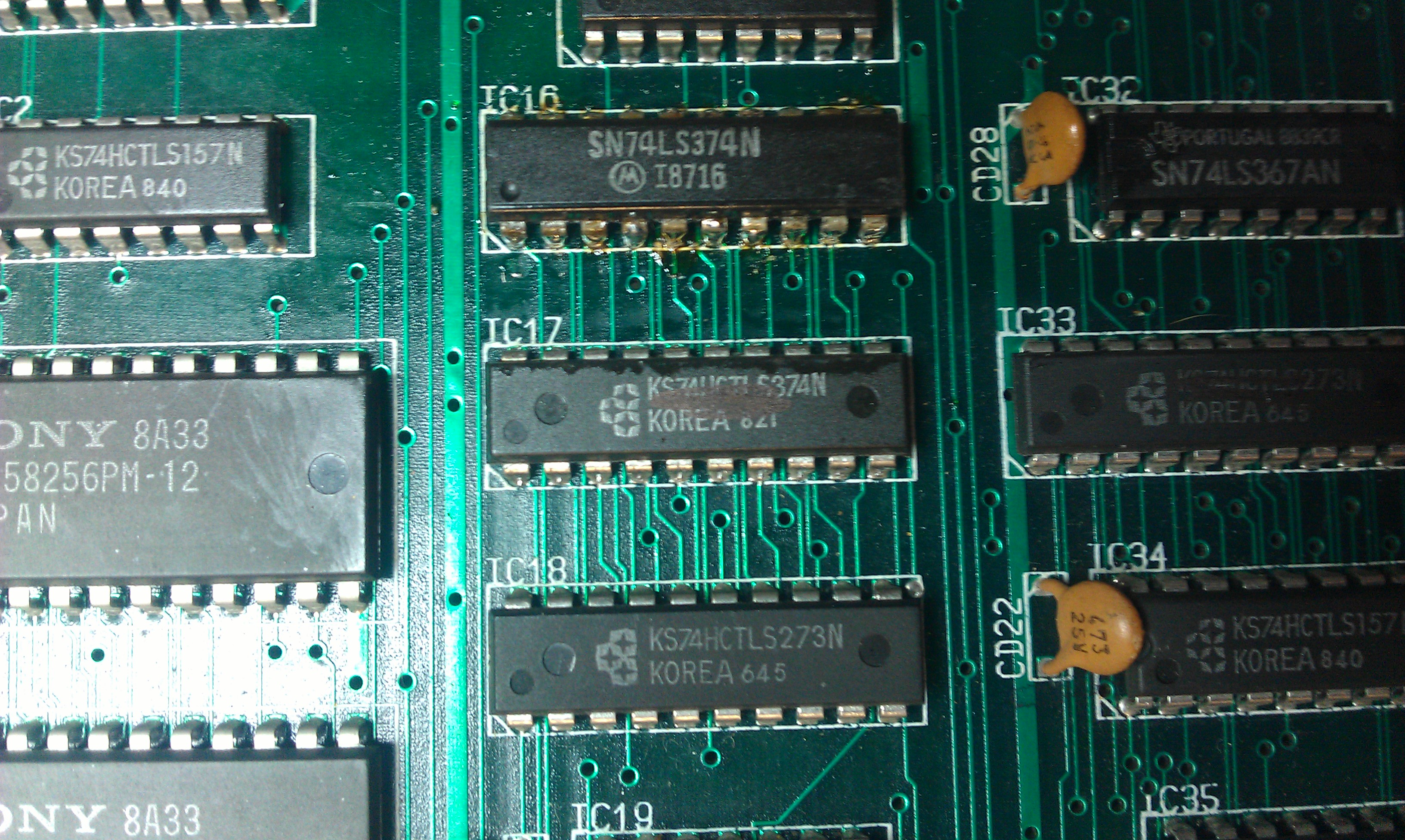
After a long session of following various signals I came across a 74LS374 chip.

This had all its inputs stuck low but according the the scope had a fair bit of noise on them, enough noise in fact to make my logic probe see it as pulsing HIGH/LOW. Following these inputs over to the chip next door I see a 74LS273 with its outputs giving off this crazy signal.
I replaced the 74273 and booted the game

If you look carefully you can see the lower part of the text is missing and a bit scrambled. Taking another look at that 74374 chip and its outputs are still crazy despite having good inputs. After a quick desolder and replacment I got this

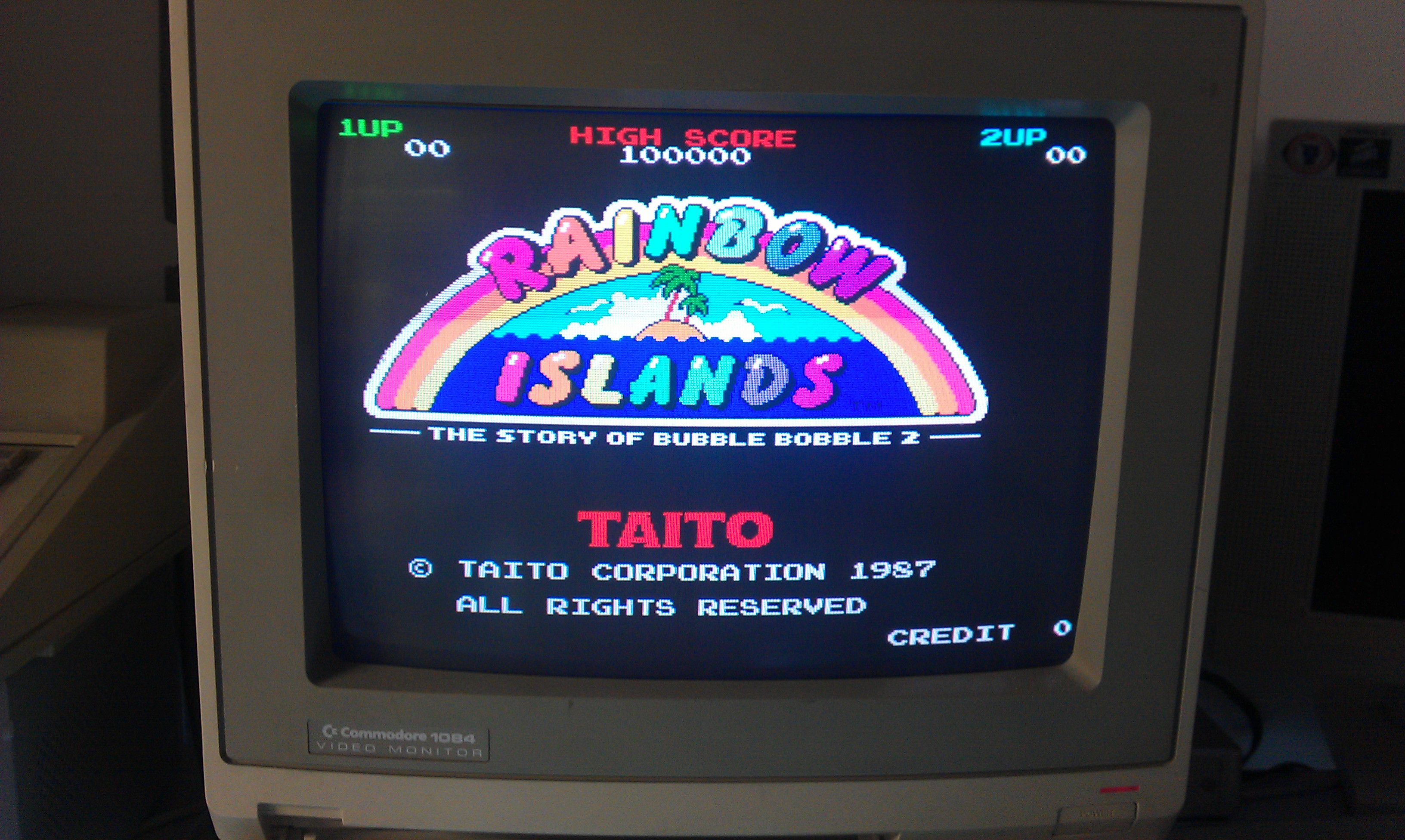
All fixed and now my conversion is totally complete.
I have left one bit of graphics the same as the Jumping. If you play the game, in the lower left corner, you number of current lives is displayed as blue stars. On the original these are small rainbows. Just a note in case I ever release my modified files and someone tries to sell it as an original or something.

 Posted by at 4:24 pm

Super Chase repair log

 PCB Repair Logs, Repair Logs  Comments Off on Super Chase repair log
Mar 022012
 

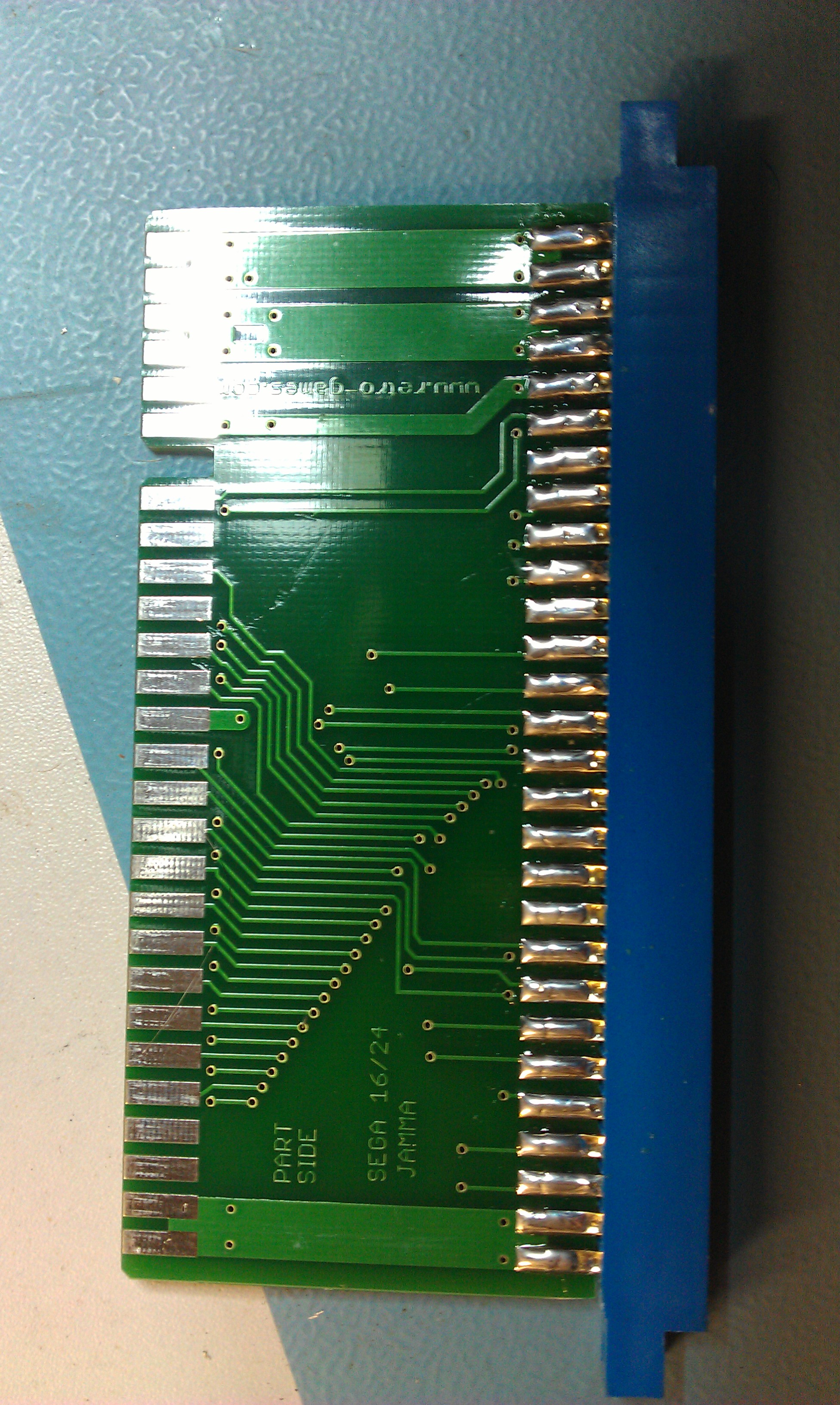
So I saw this Taito board on eBay. The seller says its broken and unknown but was most likely a Super Chase and supplied a System 16/24 adapter with it, which in its self is very nicely made and they can cost quite a bit.

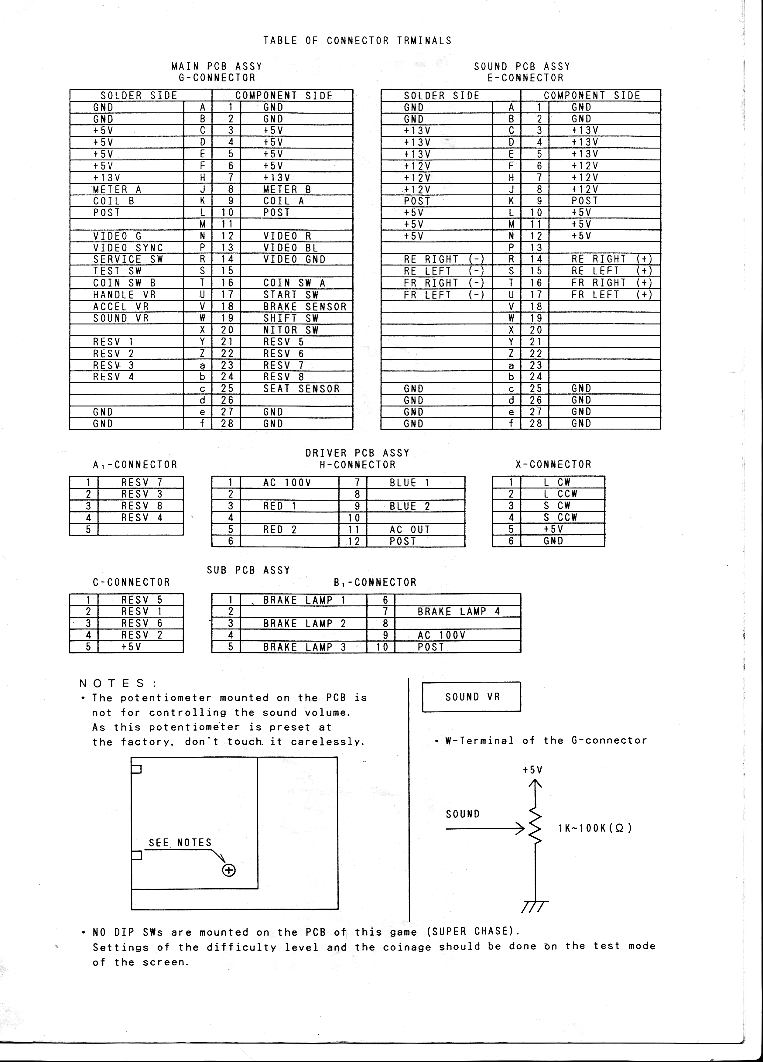
Only thing is, Super Chase is not a System 16 or 24 pinout.

*pinout supplied by Stefan Lindberg

I made a quick and dirty adapter up with and tested the board, dead.
Now I made a very stupid mistake at about this point. I moved the board down from the test bench and into one of my cabs just to rule out any voltage issues that ive seen before BUT for some unknown reason I left the pinout adapter in the test rig.

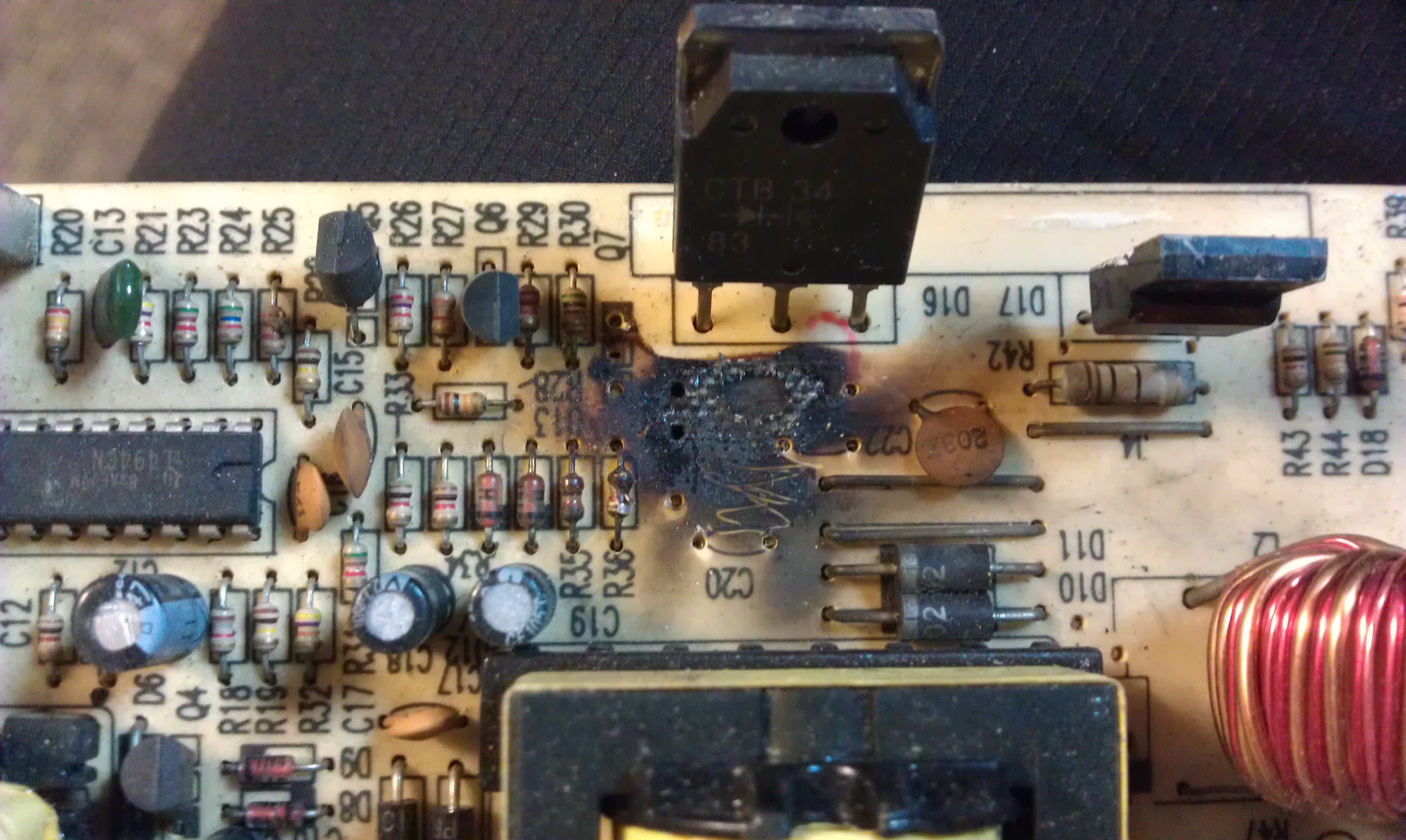
After the smoke dispersed I checked the damage.

Power supply is fried. Turns out, without the adapter I tied the +12v line to the +5v line and destroyed the PSU.
At this point I didn’t hold out much hope for the board anymore but tested it anyway.

The board was unsurprisingly still dead.

I check the RESET and HALT lines on the CPU, the watchdog was doing its thing.
Pulled and checked the program ROM’s and 2 didn’t match.
A strange thing here. One has only 1 byte difference right at the end and the other was clearly trashed with random read outs at every read.
I copied the first dump over to MAME and ran it. Turns out this is probably a different region to the one in MAME and that byte difference either displays the country warning screen or not. Mine does not.

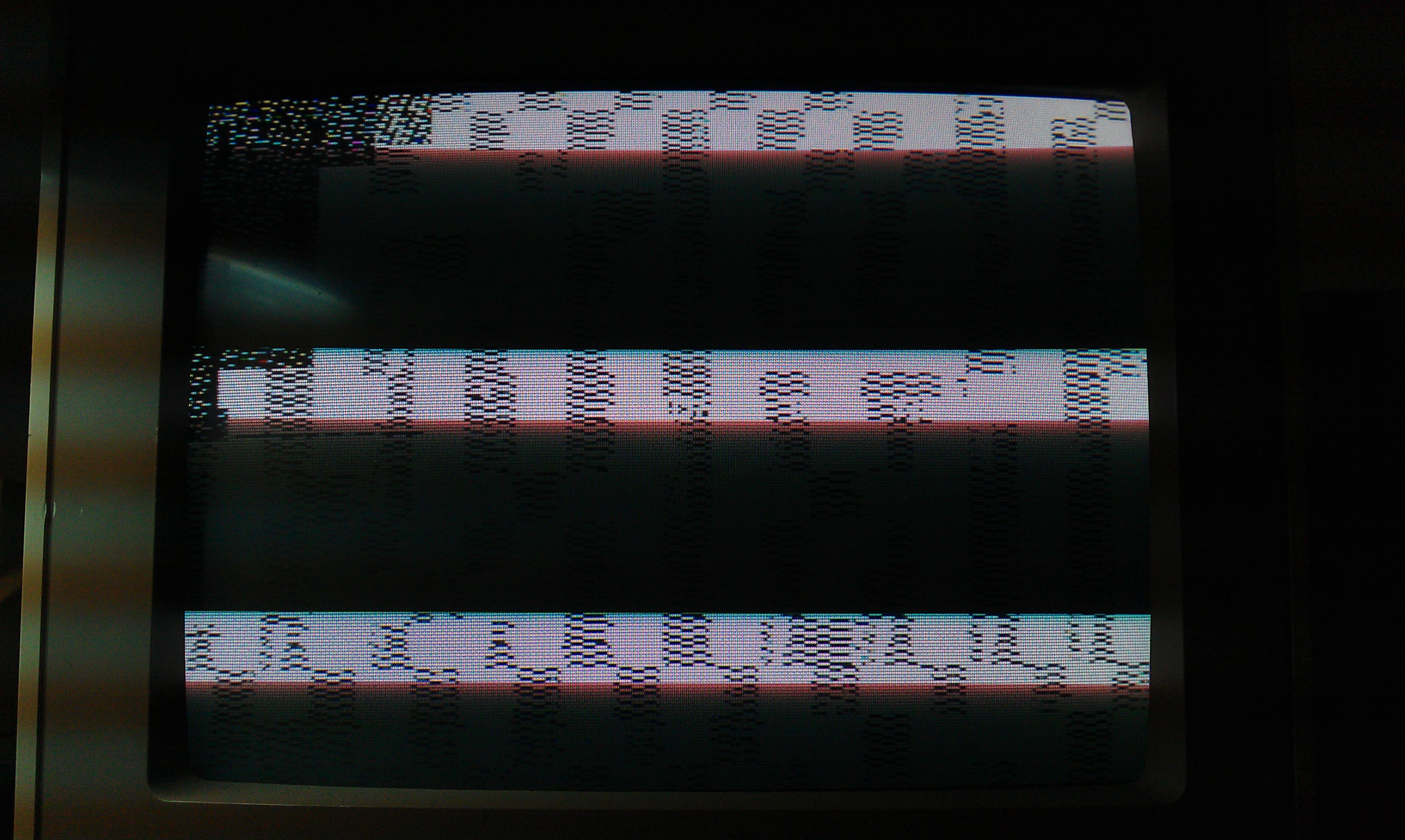
I got nothing but a bit of garbage on screen

I fired up MAME and checked what the game should be doing and it does perform RAM checks. I also saw in the code that it has RAM fail messages on screen should it encounter a problem.
Probing around the board in this state didn’t help at all as the watchdog reset everything before I could really see what was going on.
After a quick look at the CPU code I see I can bypass the shared and screen RAM checks very by changing only 1 byte. I did this and replaced the relevant EPROM and watched the game boot

So the screen RAM is at fault. The screen RAMs are the 2 Sony 58257 chips in the center of the board.
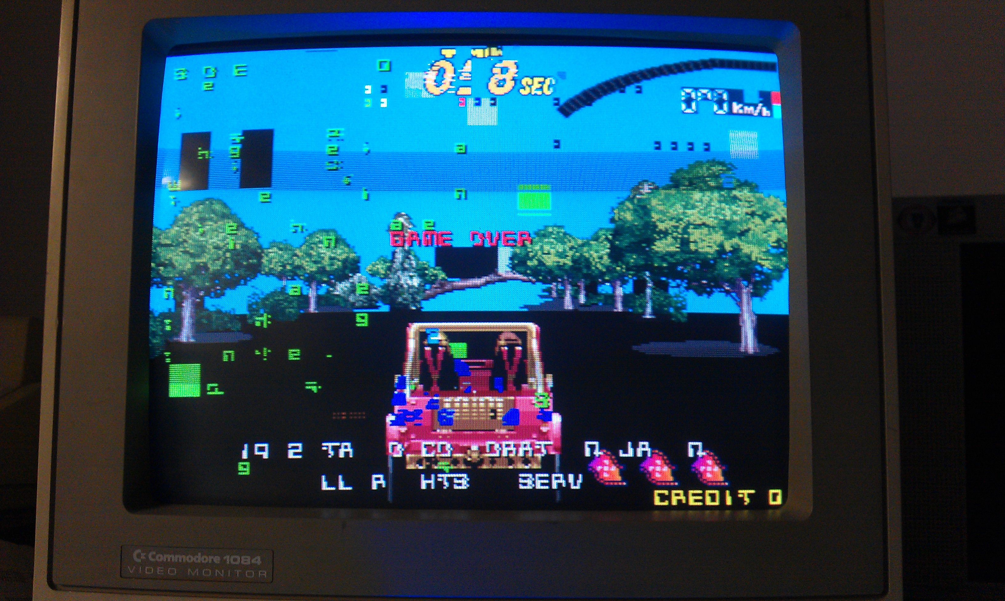
I pulled both of these and both failed. Replaced them and the game boots once more.

A narrow escape I think. This will hopefully teach me to slow down a bit, but I doubt it

 Posted by at 12:52 pm

Jumping repair log #1

 PCB Repair Logs, Repair Logs  Comments Off on Jumping repair log #1
Jan 042012
 

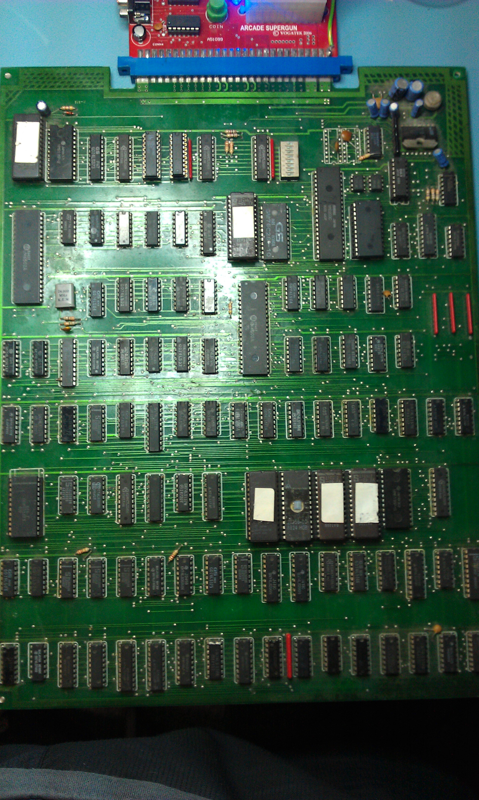
Got this Rainbow Islands bootleg yesterday.
The game worked when I tested but was told about a dodgy ribbon connector before buying it so decided to take a look. Not sure what happened after that but the board refused to boot.
After finding a few stuck address lines I decided to check the program ROM’s. Found 3 that would not read properly so I replaced them.
In MAME it lists 2 of the program ROMs as being from the genuine Rainbow Islands set but these are double the size so needed to be split into 2 files and burned to 27512 EPROMs.

Probably worth mentioning that if you use the older 2005 ROMIdent program then the dumps from Jumping actually show up as 2 separate ROMs. Must have been like this at one time.
Booting up now gives me a screen of garbage

Every now and then I could make out a “SCREEN RAM ERROR” message. The screen RAM is located on the second board and suspected this is what happens when the ribbon connector got a bit wrong but couldnt get the game to boot again no matter what I did so I decided to socket the 68000 cpu and see what was going on, kinda wish I hadnt now as I got this

Accepting the error just kept flagging more “tied bits” errors. Turns out this was a red herring as these lines are controlled by a PAL20L8 chip and everything passes if this is removed. Wasted a little bit of time on this.

After taking a careful look at the connector it turns out the plastic housing that holds the ribbon cable in place was damaged and this allowed the ribbon cable to come away from the pins. I properly reseated the cable and tested, the board now fires up in all its crazy bootleg glory

The game plays pretty much like Rainbow Islands does but some of the sprites and names are different and I think the secret rooms don’t work too well.

This game has 3 PAL chips on it, unfortunately all are security locked and I am only able to read 1 of them (might be able to read the one on the video board but never tried).

 Posted by at 7:11 pm

Pocket Gal bootleg repair log

 PCB Repair Logs, Repair Logs  Comments Off on Pocket Gal bootleg repair log
Nov 212011
 

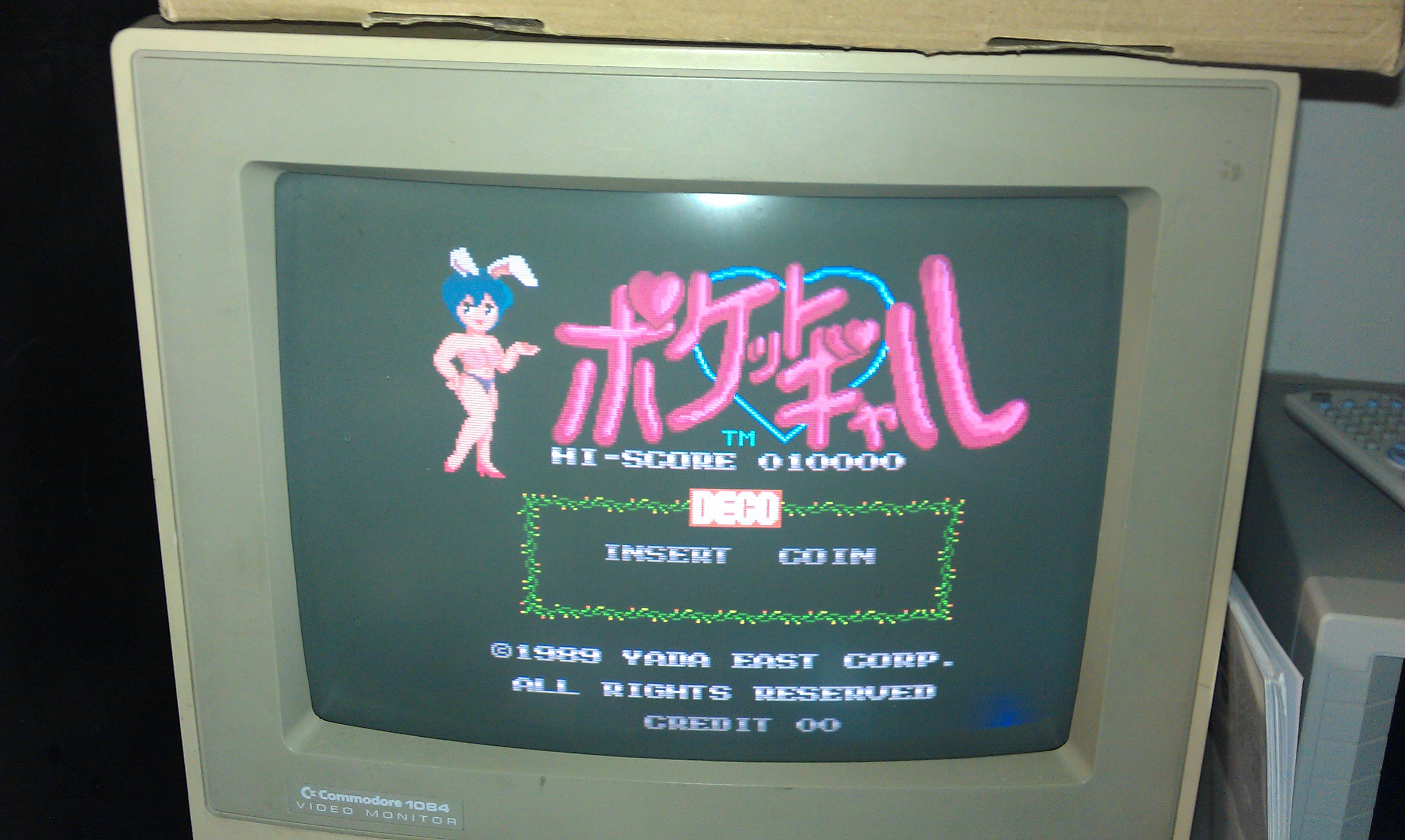
Another decent fella from a forum was giving this board away for the price of postage.

Its been a bit quiet lately on the repair front so thought id give myself something to do. Ended up being a really quick and easy fix.
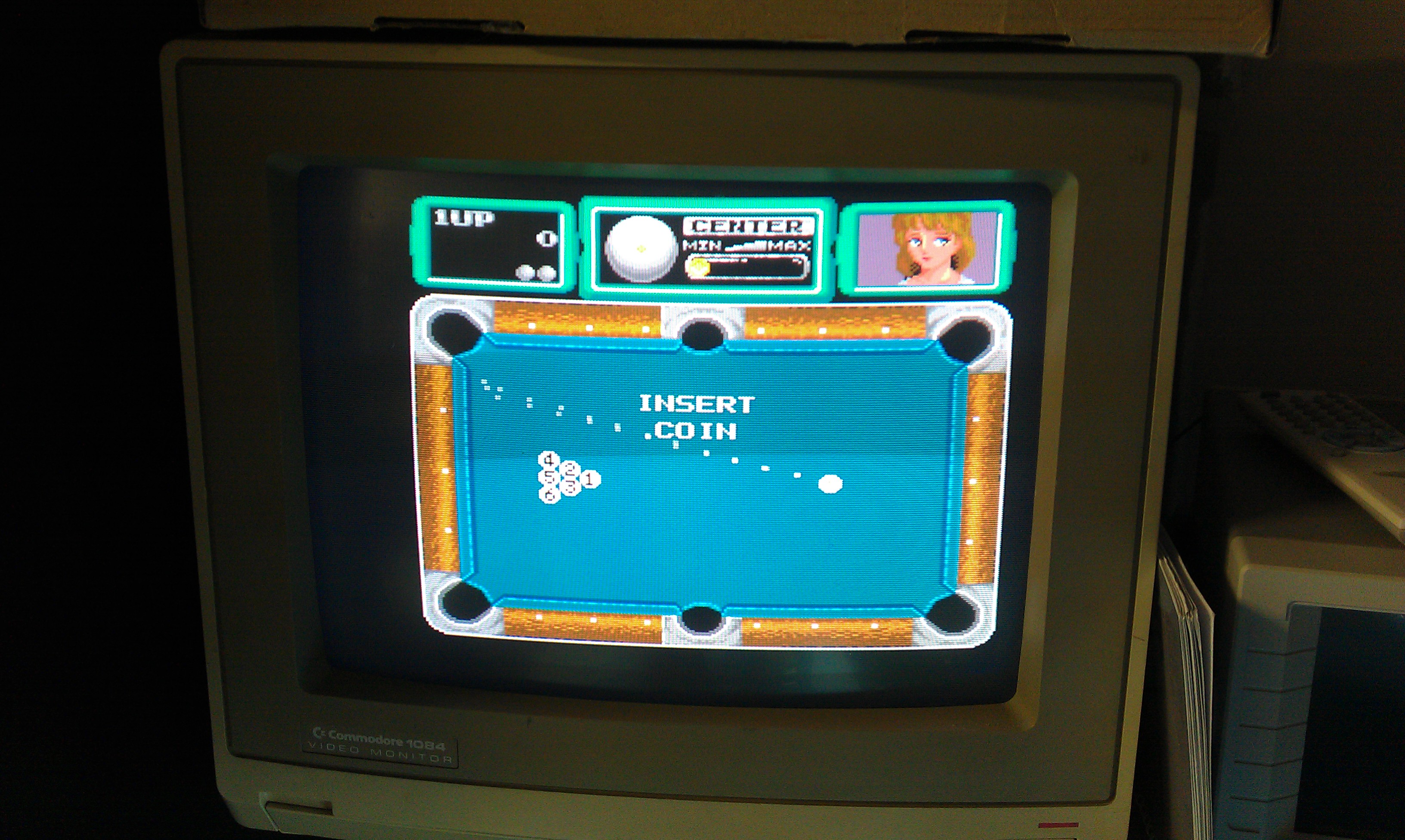
The game booted up and all the sound appeared to be there, it would even coin up but the game could not be started.

Checked pin 17 at the edge connector (Start button) and this was HIGH and it toggled LOW when the start button was pressed. Traced this through to a nearby 74LS245.
The direction pin (1) was held low connected to ground and because the ENABLE pin was pulsing it was pretty difficult to see if the inputs on the B side of the Bus were making any difference to the A side outputs. I piggybacked a new 245 onto it and the game could now be played. I desoldered it and replaced the chip, all is now working. Shame the game is utter crap!

I also took the opportunity to dump the unprotected PAL16L8. I’ve converted it to GAL and tested it. There is a PAL16R6 on there too which ill get around to doing sometime but the board is of typical bootleg quality and a bit of a pain.

 Posted by at 5:53 pm