Retrobright attempt

 General  Comments Off on Retrobright attempt
Apr 222011
 

After reading a simple guide by 1200xl over on the RCM forum, I decided to give this retrobrighting thing a go.
Retrobrighting is a process of removing the yellowing that tends to occur on old plastics. I’ll not go into the science behind it cause i don’t really know it.
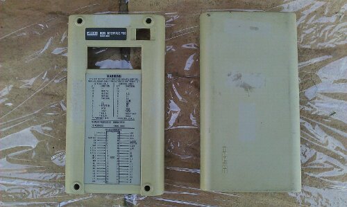
As a test subject I used the casing of one of my Fluke 9010a pods.

I ordered some peroxide online and this Saturday was the ideal day to try as to make this work, sunlight is required.
Apply a nice thick coating of the peroxide to the washed down plastic and wrap it in clingfilm, then place it in the sun for a few hours turning it every so often to get all sides.
Probably should mention that rubber gloves are a must for this job as the peroxide doesn’t feel good on bare skin!
After its been roasted, remove the clingfilm and wash off the peroxide and let the plastic dry.

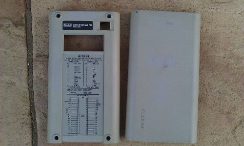
Pleased with the results for a first attempt and have since don’t the body of the Fluke with better results.
I was advised to apply a UV treatment after this as the yellowing will return but at this point I haven’t got any. I’ll get some ordered though.
Will no doubt have more stuff to do in the future.

Fluke 9010a ROMs Ver 2B ROM dumps

 Downloads  Comments Off on Fluke 9010a ROMs Ver 2B ROM dumps
Apr 222011
 

Got around to dumping the ROMs today for backup purposes.
The version installed is 2B (or 2.1 according to the stickers). I know there is a v3a kicking about somewhere but no one knows what the differences are between them so I wont bother upgrading mine.
The naming scheme for these is taken directly from the ROM stickers.
Also included in this ZIP is the MCU dumps for the keyboard and the tape drive unit.

Fluke 9010a Files

CAPCOM Commando repair log #3

 PCB Repair Logs, Repair Logs  Comments Off on CAPCOM Commando repair log #3
Apr 162011
 

Whilst soak testing the Commando board I had recently repaired for someone 2 bad things happened.
First the music disappeared
Second the pictures vanished.

I checked the RGB outputs with the scope and the signals looked a little weak but should be fine. I checked the SYNC signal and this was stuck HIGH.
Followed the signal back from the edge connector to a 74LS138 IC @ location 5L and the outputs on pins 3 and 4 were both stuck at just under 1v according to the scope.

The inputs to the IC were fine. I piggy backed a working LS138 and the picture came back normal.

The sound fault was fairly simple too.
The first thing I did was check the RESET and HALT lines on the Z80 CPU. These were fine and not stopping operation. Next I checked the clock signals on the Z80 and the Yamaha 2203’s. The Z80 was fine but there was nothing on the 2203’s.
The clock signal for these 2 come from a nearby 74LS74 IC who’s outputs were obviously dead but all the inputs were “as schematic”. I pulled this and testing it, it failed and a replacement has restored the sound fully.
Finally this is in good health once again and hopefully it will stay that way for a while longer, although with the amount of Fujitsu TTL IC’s on the board I very much doubt that but it is 26 years old now!

16bit ROMs byte swapped

 General  Comments Off on 16bit ROMs byte swapped
Apr 132011
 

Just a note to anyone attempting to burn ROMs that are available online.
This mainly concerns the ROMs for 16bit systems such as the Amiga, Atari ST, Megadrive etc.
The ROMs available for use with emulators, like the Kickstart ROMs for use in WinUAE, have all been byteswapped. If you are going to burn these into an EPROM then they needs to be byteswapped. This can be done using many different tools. I use my own drag and drop program to do this quickly but I know Hex Workshop (and probably most other hex editors) can do this too.

CAPCOM Commando repair log #2

 PCB Repair Logs, Repair Logs  Comments Off on CAPCOM Commando repair log #2
Apr 102011
 

Got sent a Commando board for repair a while back and have finally got around to giving it a test.
I spent a little time going over the board doing the visual inspection prior to booting up. On the bottom board a 74LS245 had been removed and was just sitting in the board loose but most of the traces going to the IC had also been lifted, I suspect during a bodged removal.

image

I refitted the IC (after testing it), cut the lifted tracks off the board and ran some kynar to the relevant points.

After spending a bit of time making another adapter up to run the game I saw the graphics fault.
All the sprites were barely visible and sometimes were gone completely.
There was also some corruption on one of the screens.


The manual for this game is online and in the back of this are the schematics for the game. Nice. Also, as its CAPCOM, the schematics are nicely split and labelled up in sections.
After seeing the fault I was convinced that RAM was to blame. I scoped a section of 4 x 2114 RAM chips on the lower board. All had good looking address lines but the data lines looked very odd like they were struggling to drive the lines low. I interrupted a couple of pins and graphics started to come back so I pulled it and testing it, FAIL. One replacing the RAM only half the sprites came back with jail-bars running through them. I ended up pulling 3 in total which was quite lucky as I ran out of RAM replacements.
All graphics are now returned to normal.

As for the corruption on the screen. Thanks to MAME I was able to determine this to be an unused part of the screen that my RGB to VGA converter decided to throw in there to confuse me. In a cabinet the screen would be adjusted to remove these borders.