X Multiply repair log #1

 PCB Repair Logs, Repair Logs  Comments Off on X Multiply repair log #1
Aug 012010
 

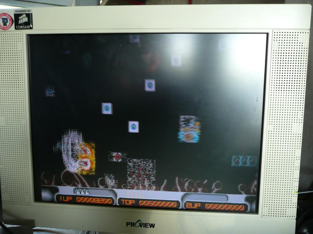
Started off as a physical problem with corroded legs on MASKROM’s giving corrupt graphics on sprites.

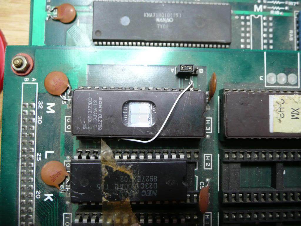
Three legs were corroded on MASKROM T44.00, which is an NEC 23C1000. After a little asking about, I was told the EPROM equivalent was a 27C301 (non JEDEC).
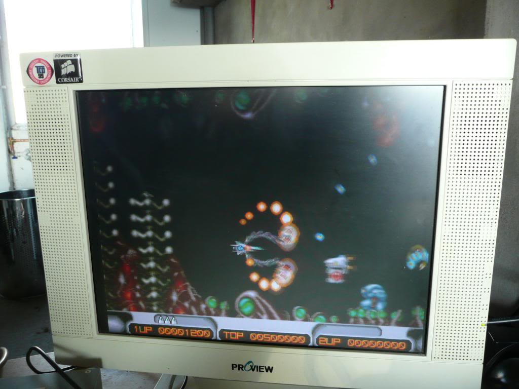
I obtained a 27C301 eprom and burned a T44.00 from MAME. Pretty much all the graphics were back but there were some white blocks around the ship sprite and certain enemy bullet sprites. Found a broken track from pin 20 (chip enable). Repaired this and the white boxes are now gone from the ship sprite. There were still white boxes around the projectiles. I have now confirmed that with an original ROM the game works fine.

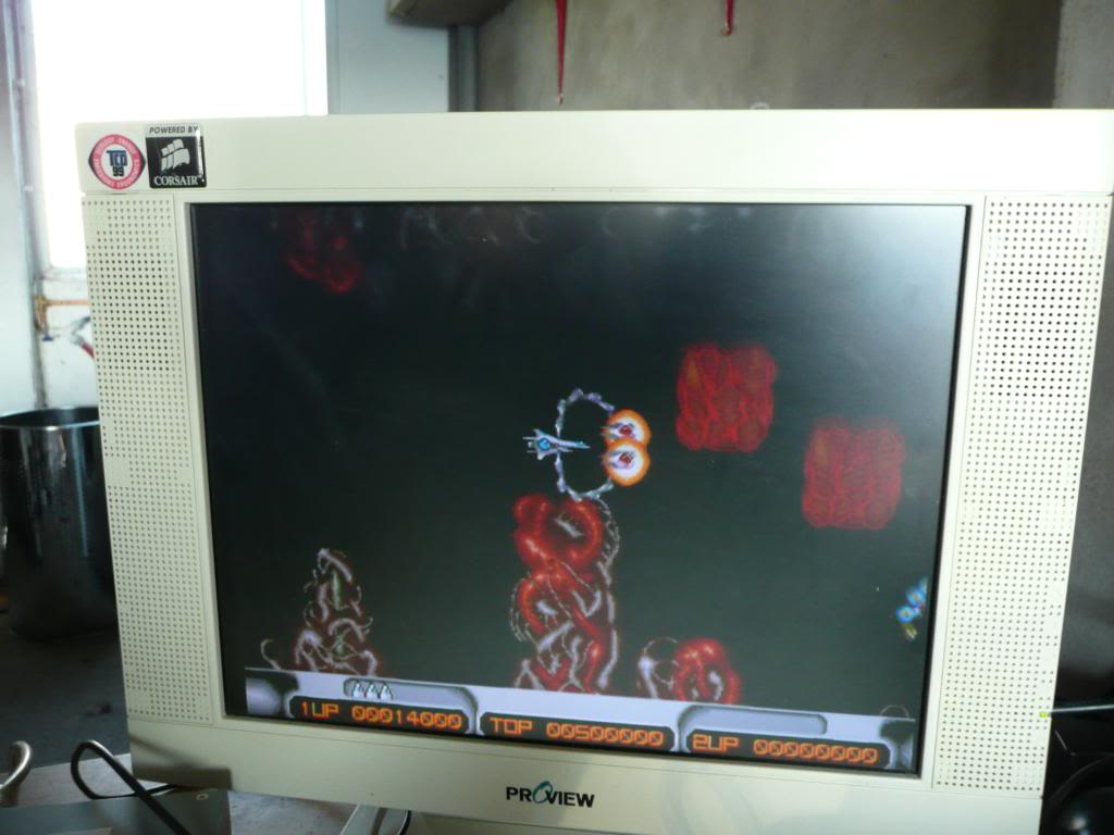
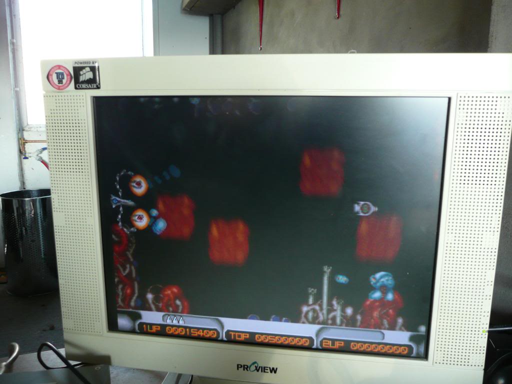
I took a closer look at the pinouts from a 23C1000 MASK ROM and a 27C301 EPROM. MASKROM’s have less pins than their EPROM equivalent mainly due to not have programming pins but also this ones only has one enable pin (pin 20) and the EPROM has separate /OE and /CE pins. I lifted pin 2 and soldered a wire from this to pin 22 on the EPROM and fired the game up, all the graphics are now 100% working. I initially thought this corruption was down to the speed of the EPROM but now I know otherwise.

Graphics fault
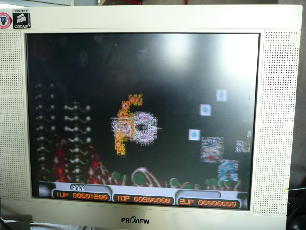

Fixed


Bomb Jack repair log

 PCB Repair Logs, Repair Logs  Comments Off on Bomb Jack repair log
Aug 012010
 

Received an “untested” Bomb Jack board from eBay.
It appears to be a bootleg/original hybrid. The A board was a bootleg, the one with only 2 x AY-3-8910’s on it and the B board is from an original.

The game was missing the green and blue colours and sound was stuck in a constant repeating loop from power up.
The RGB, sync and video ground go to a 5 pin header on this bootleg, not a 6 pin header, the previous owner was clearly not had an adapter or plug for anything on this board and had soldered the wires directly on, had also melted all the plastic supporting these 5 pins so a couple were shorting to ground, easy fix. The sound had a corrupt EPROM, I erased and burnt a new one, still no change. The RAM had already been socketed so I tested it and it came up clear. Checked the Z80 with the logic probe and found the address lines were all high except for a couple that were pulsing. De-soldered it and tested it, it failed on pretty much everything, replaced it and now the sound was working but seemed to be lagging behind when compared to MAME. I put in a new RAM and the fault was fixed. Swapped the RAM back and fault returned. This RAM works fine in my other boards so am putting it down to RAM speed.

Double Dragon repair log #1

 PCB Repair Logs, Repair Logs  Comments Off on Double Dragon repair log #1
Aug 012010
 

Got a broken DD board off Ebay. Original fault was the picture was white with black blocks.

The board had many repairs done in the past, some bad some good, so I started by removing them all and checking them through. One of them was a length of kynar replacing a lifted track but was going to the wrong place! fixed that but made no difference at all.
Some of the RAM had been socketed but had used badly cut down sockets, replaced these also.

After a long time inspecting the underneath of the boards and fixing a LOT of broken tracks I noticed a few chips on the CPU board had a lot of flux around the solder points but no sockets had been fitted here. They were all 74LS273 chips and one was a Fujitsu! Put the probe of the Fujitsu chip and most of the pins were dead. Desoldered to find a lot more broken tracks. Tested the old chip, it failed miserably. Put a socket in, pulled the schematics for the CPU board and repaired all the tracks that were broken. New chip inserted and fired it up, all back to normal.

Super Contra repair log #1

 PCB Repair Logs, Repair Logs  Comments Off on Super Contra repair log #1
Aug 012010
 

This baffled me for a long time but ended up being really simple.

When the player died and the Continue countdown came up, it would only count down to 7 then returned to the title screen. Logic suggests that this shouldnt be the case and checking in MAME proved it.
The problem ended up being button 1 for player 2 was stuck on.
Traced the stuck low signal through resistor array CRA3 and to a 74LS253 IC @ D19. Pulled and replaced the IC now all is happy.

Golden Axe repair log #1

 PCB Repair Logs, Repair Logs  Comments Off on Golden Axe repair log #1
Jul 242010
 

I have decided to take a look at the Golden Axe problem today.
The problems with it are:
1. None of the inputs register
2. There is no sound

Normally faulty inputs are easy but not with the System 16 board. The inputs are controlled and isolated by 8 NEC2501 chips. I couldnt find a single bit of info on these chips but as luck would have it when I removed the chip from the board there is an alternative printed on silkscreen of TLP521-4. The datasheet for these is readily available and its description is a photo transistor. I wasnt prepared to believe that all 8 of these chips had gone so I traced the pinout back to the edge connector. It turns out that pin 4 on the solder side of the edge connector NEEDS to be connected to its own +5v as this supplies the voltage to the photo transistors and in my haste to get an adapter up and running I never wired all the points in. Lesson learnt. All inputs have now been tested working.
Next job, sound. I have dumped the 2 ROMs associated with the sound and checked them against MAME, both are good.
NOTE: The SEGA branded MPR- maskroms can be read as a 27c301 with a slight wiring mod.

There is a Z80 on the board which is the processor for the sound, this was dead. Replaced the processor and full sound is there.

Very happy to have this one up and running.