Jan 062016
 

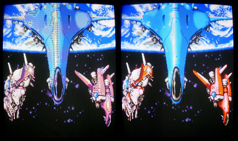
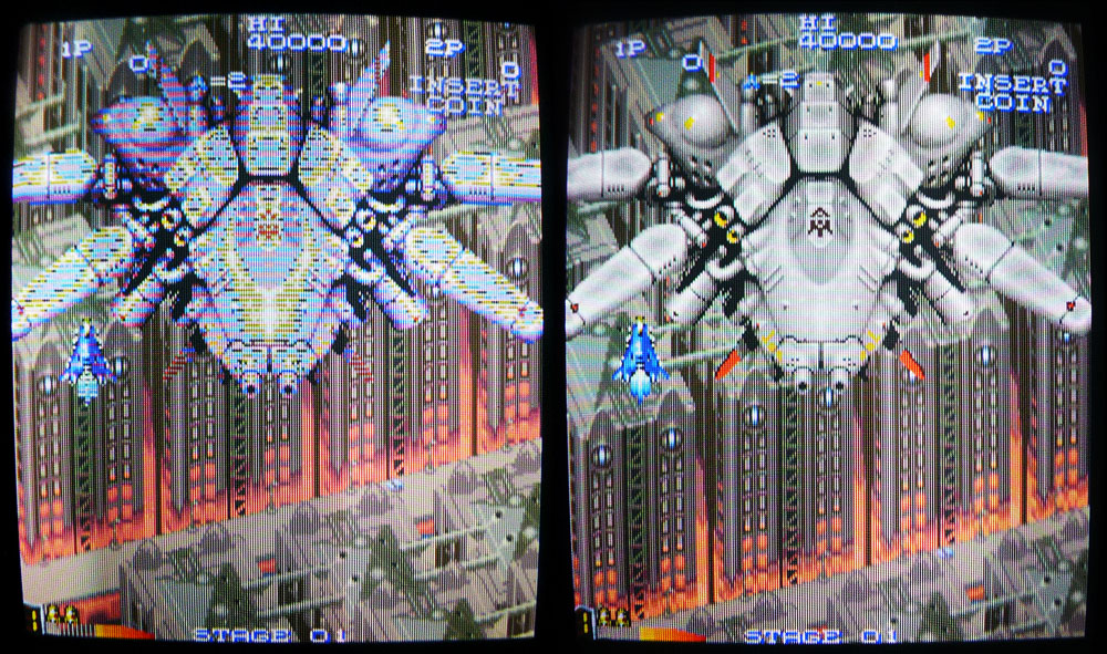
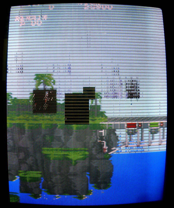
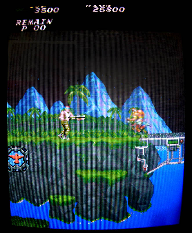
Recently got this Final Star Force PCB with graphical glitches on the sprites.

fstarforce1

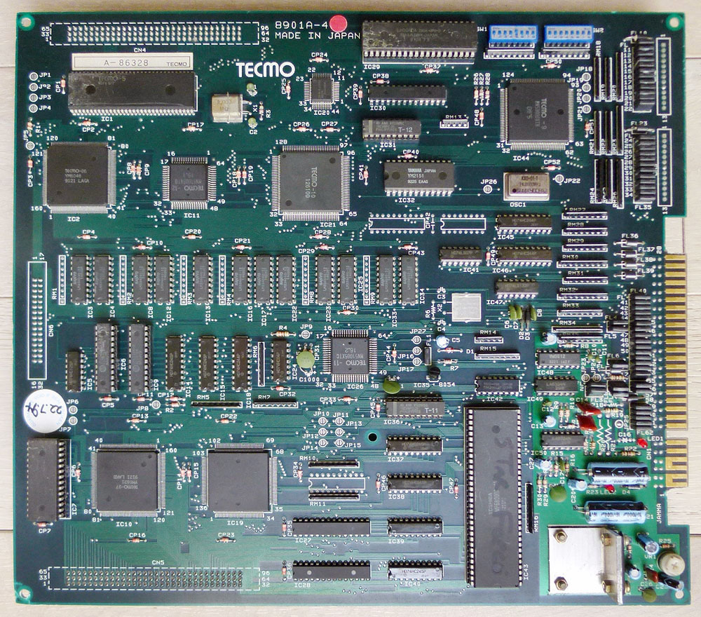
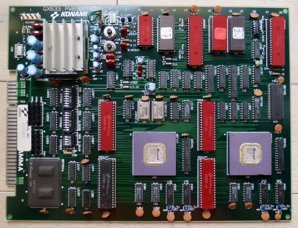
This game uses a motherboard (pictured above) and has a romboard on the other side fitted with no other chips than the game’s ROMs.

All the ROMs were tested ok on my programmer and cleaning the connectors and looking at the signals, everything seemed fine with that romboard.
The motherboard has a rather simple layout with a lot of RAMs, some ASICs and a few TTLs. After a few hours looking for suspicious signals, I finally found the faulty ones.

There is a row of 12 Sanyo LM33464G RAMs (64k-word x 4-bit). Two of them were bad (the ones at IC22 and IC33). Piggybacking them with new ones partially brought back clean sprites, even if there were a few glitches remaining. These glitches totally disappeared after replacing the RAMs.
As these models of RAMs are a bit uncommon, I took compatible TMS4464 as replacement (highlighted in red):

fstarforce2

Here are before and after pictures:

fstarforce3 fstarforce4

Gryzor repair log #1

 PCB Repair Logs, Repair Logs  Comments Off on Gryzor repair log #1
Dec 142015
 

First I would like to thank hezkezl and channelmanic on the KLOV forum for their help when I started diagnosing this Gryzor PCB last Year.

I finally got it repaired…

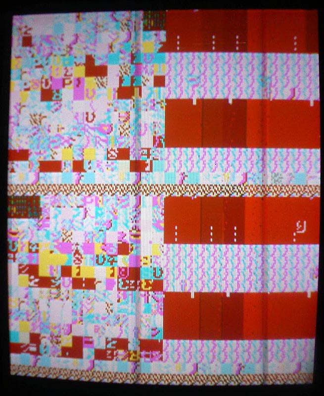
1) I got first stuck at this screen on boot:

gryzor0

Dumping the program ROMs at 17A and 18A and comparing them with the ones from MAME revealed the checksum for the one labeled 633J2 at 17A was bad so I burned the rom from MAME on a 27C512 EPROM and put it in place but no changes.

While checking the PCB with a scope, I traced a suspiciously weak signal from a couple of TTLs (which seemed ok) to a Fujitsu MB8464A RAM. Pins #7, 8 and 9 on this RAM were not pulsing (signal was stuck at 1,7 V).

These pins are address lines. They are connected to:
– Pins 7, 8, 9 on 18A and 17A (program ROMS)
– Pins 9, 10, 11 on 22A (63C09 CPU)
– Pins 114, 115, 57 on 10E (custom chip)
– Pins 114, 115, 57 on 18E (custom chip)
– Pins 1, 2, 3 on 14D (LS138 – Address decoder for I/O ports)

Replacing the LS138 at 14D didn’t change anything, not really surprising as it was related to I/O (but I didn’t really know that back in the time when I did it) so next I decided to replace the 63C09 CPU at 22A… And the game booted ! …with big graphical issues and no sound:

gryzor2

2) Graphics roms are the 4x 40 pins mask roms located at 7D, 7F, 16D and 16F. I’ve read online some people having problems with these chips and needed to replace them. The content of these roms is 256kb but I only had 512kb 27C400 EPROMs (equivalent pinout to mask roms) so I needed to double the size of each original 256kb roms to fit my 512kb EPROMs. A few tries revealed I had 3 bad roms (the ones at 7F, 16D and 16F) among the 4. All the graphics were now fine:

gryzor3

3) Good progress, but still no sound…

There are 2 chips in the sound part (located at 11A and 11B) that have their reference writings scrubbed, probably in factory to avoid bootleggers reproducing it. I’ve looked online to see if I could find pictures of other PCBs that could still have these labels visible, but all the ones I found had their writings scrubbed.

Anyway, it looked like these 2 chips were the sound generating chips. Looking in the MAME driver and on datasheets revealed it was a YM2151 coupled with a YM3012 D/A converter.

Looking at the pins of the YM2151 with a scope, I noticed there was no output signal on it (pin #21) while most of the other pins on the chip had pulsing signals. I desoldered it to put a new YM2151 in place and got a pulsing signal on the output pin… But still no sound.

I then started looking at the pins of the 63B09 sound CPU at 15A and found 2 dead signals at pins #16 and 18. These are address lines so I suspected the CPU and changed it. The sound was finally back. Everything is working fine now !

Here is a picture of my PCB with all the bad chips I replaced in red:

gryzor4b

Heavy Unit repair log #1

 PCB Repair Logs, Repair Logs  Comments Off on Heavy Unit repair log #1
Dec 142015
 

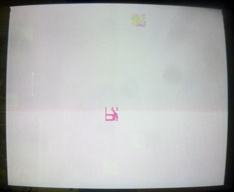
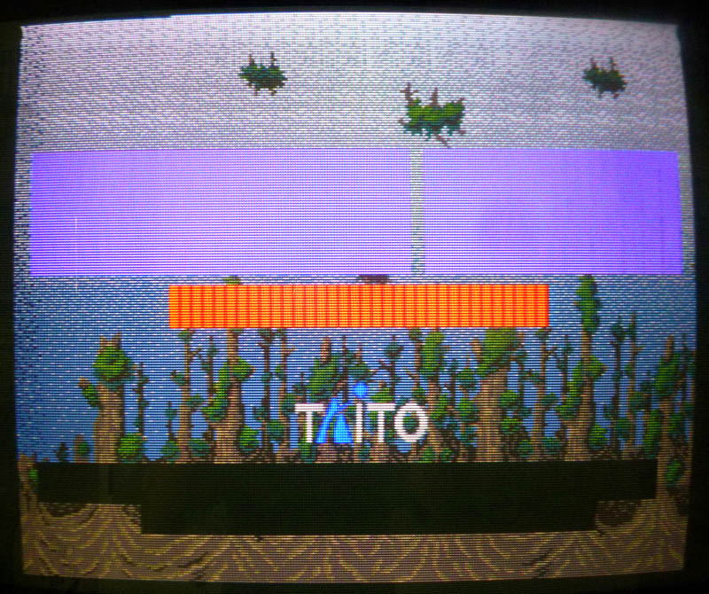
I got a dead Heavy Unit PCB with a white screen on boot:

hvyunit1

Looking at the MAME driver for that game I could see where the program roms were located (5C for the main program rom and 5P for the sub program rom).
I started probing around the CPUs and program roms. The CPUs (2 x Z80) seemed active and the program roms had pulsing signals on most of their pins. A few were inactive and connected to nearby GALs (labeled MD-500 and MD-501). All the I/O pins were stuck low on these two GALs while they had pulsing inputs.

There are 3 GALs in total on that board, MD-500 is connected to the main program rom, MD-501 is connected to the sub program rom and MD-502 is connected to the sound rom.
Surprisingly all these 3 GALs had inactive I/O pins. I got a working Heavy Unit PCB from a friend, compared the signals on the GALs and saw that almost every I/O pins were pulsing on the 3 GALs.

These GALs were not available online so I started desoldering them on both PCBs.
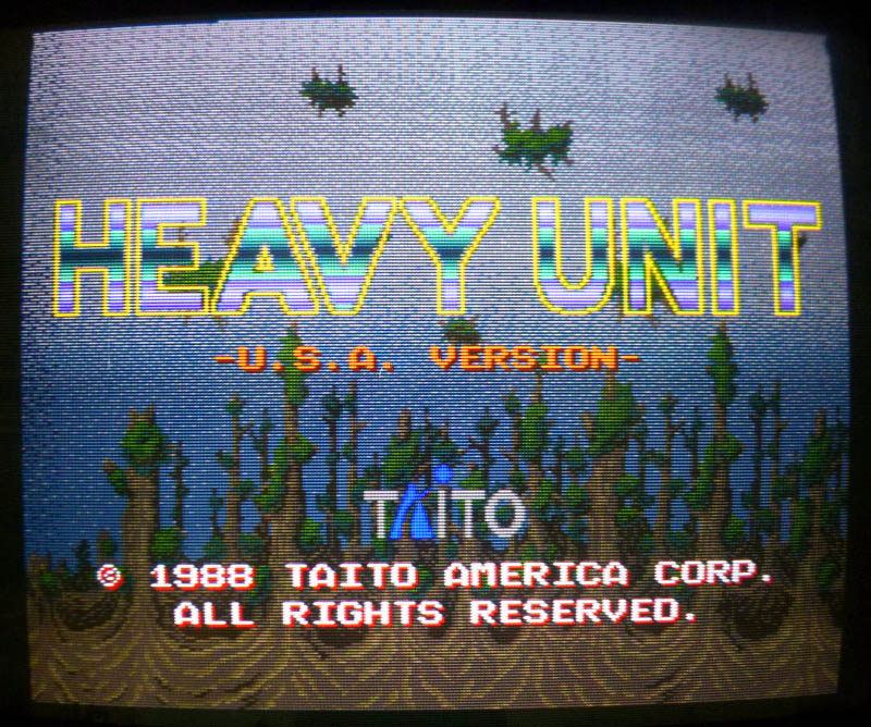
I put sockets on the dead PCB, socketed the GALs from the working board and the game booted ! …but with partially missing graphics (I had colored squares instead of sprites):

hvyunit2

Looking at the PCB I supposed the main program rom at 5C was not original as it had no label. Dumping it revealed it was from a US version. Looking at the MAME driver, I could see that every of the 4 versions dumped in MAME had a different ROM layout and my version was not dumped (the numbers on the labels were not in MAME). Particularly, there was a 512kb ROM at 2F on every versions in MAME that wasn’t soldered on my PCB, although I found its content spread on 4x128kb ROMs at other locations. The main program ROM was probably looking at the wrong location so I soldered a socket at 2F to put the 512kb ROM (from one of the MAME dumped versions and labeled B73_08) and the sprites were back. 🙂

hvyunit3

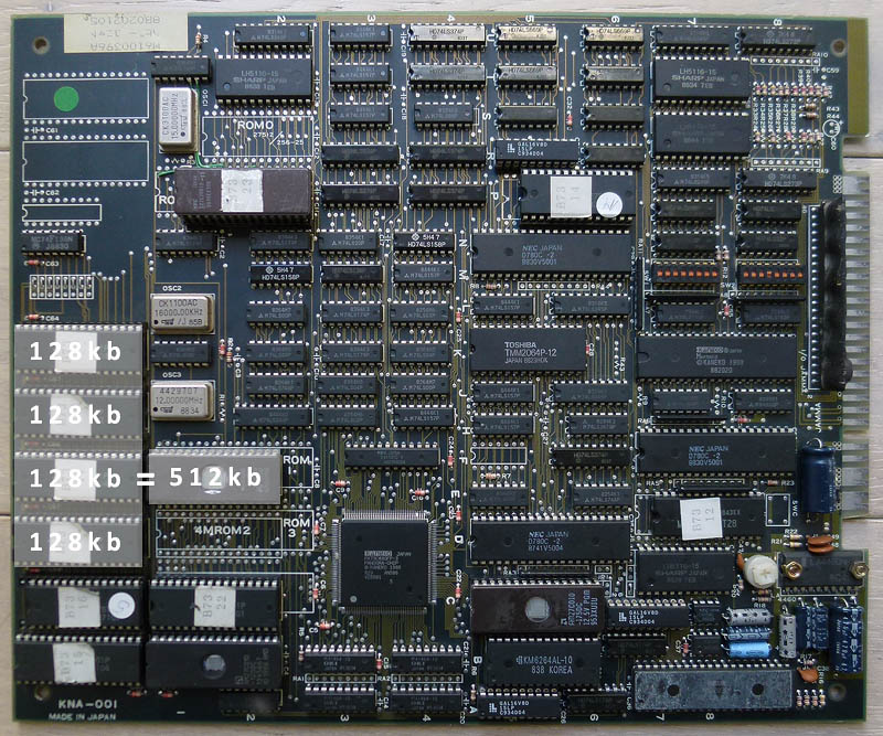
Here is my PCB with the added 512kb EPROM from MAME at 2F (equivalent to B73_17 + B73_18 + B73_19 + B73_20 on the left):

hvyunit0

ps: I’m still looking for the original program ROM for my PCB (labeled B73_24 and located at 5C) to be dumped so I could remove the 512kb at 2F and use the original 128kb ROMs already present on the board. I suppose it is a japanese version.

ps2: I wanted to dump the GALs from the working board but they were protected. To dump protected GALs I needed to use a method by Charles MacDonald. First, I used this adapter in order to read my GALs as 27C020 EPROMs: https://techno-junk.org/files/adapter-v2.png
Then, I used PD.EXE and WinCUPL to recreate the GALs from my raw dumps: https://dreamjam.co.uk/emuviews/readpal.php
These GALs are now available on https://www.jammarcade.net

Fluke 68000 POD repair log

 Equipment Repair Logs, Repair Logs  Comments Off on Fluke 68000 POD repair log
Dec 292014
 

Whilst doing some testing for Guddler over on the UK-VAC forum I thought it would be a good time to look into why I sometimes get a POD timeout error.
Normally when I get this error pushing down on the black cable that connects it to the 9010 fixes it.
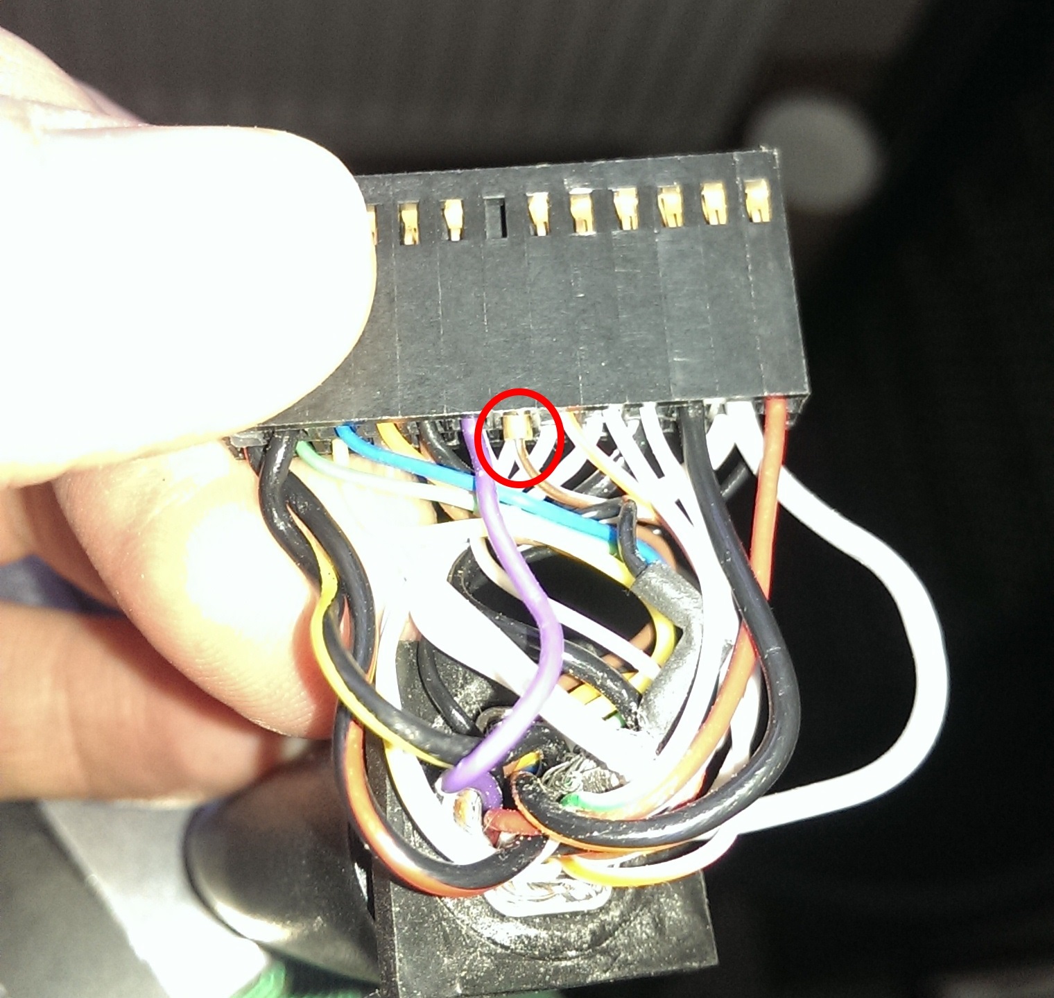
Here is the reason why
IMAG1127
One of the crimps had worked its way loose.

I carefully bent the small bard out a little and refitted. Now the POD seems to be rock solid.

Commodore 64 ‘breadbin’ repair log #3

 Computer Repair Logs, Repair Logs  Comments Off on Commodore 64 ‘breadbin’ repair log #3
Aug 062011
 

Number 3 of the 5 I brought back from RCM.
This one ended up being a bit of a pain.
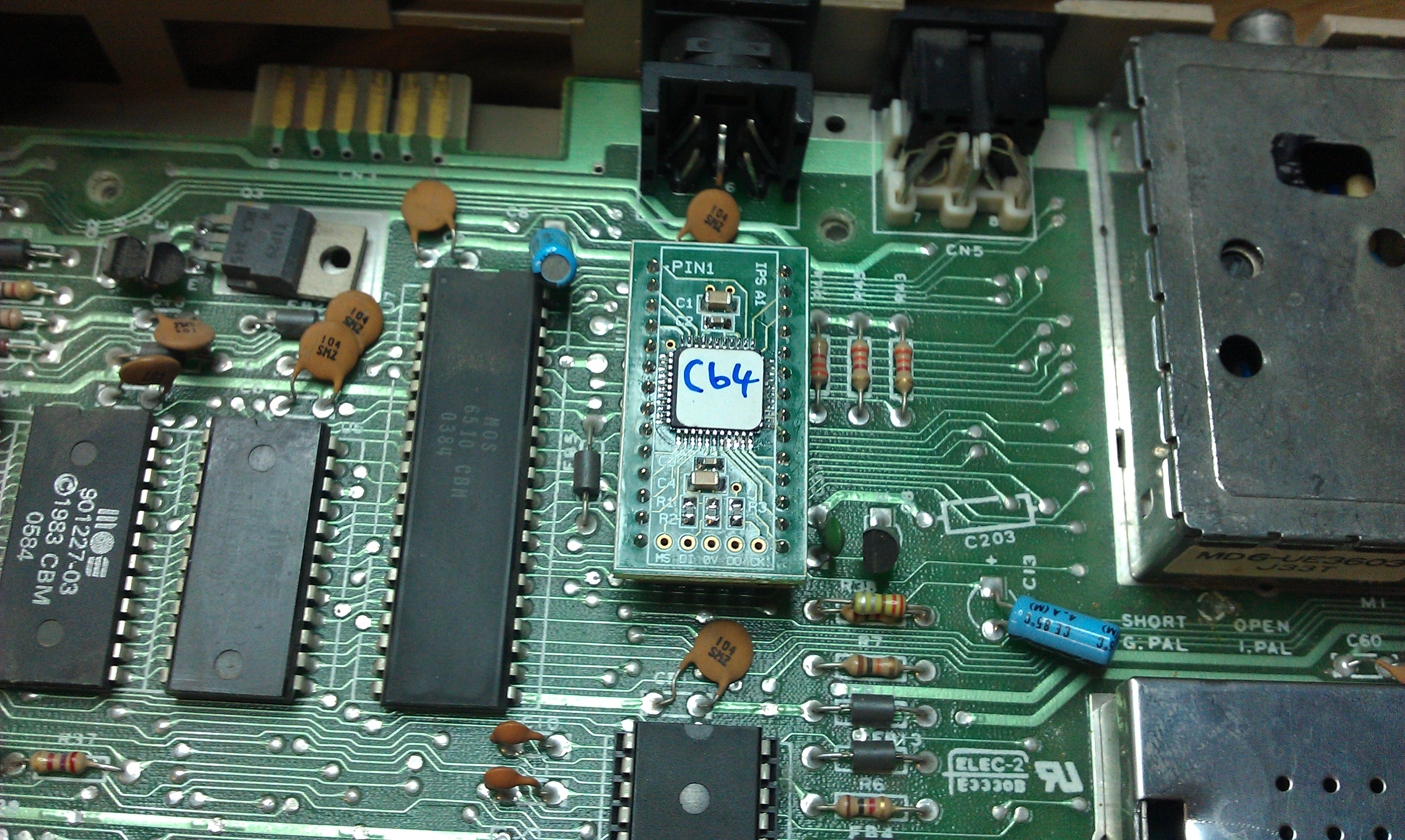
Black screen at power up. Removed PLA but didn’t have an original spare I could swap out so it was time to use the CPLD based replacements I have.

Now the 64 boots up but sometimes gave garbage on the screen and sometimes gave the normal boot screen but with 6336 bytes of RAM.
My initial thinking was a RAM fault so went round all the RAMs and doing a thorough soak test on them but it yielded absolutely nothing.
I plugged in my diagnostic cart and it would flag up a different RAM as being at fault each time. This suggested that the 74LS257 data selector for these RAMs was shot. I removed U13 first and it failed its tests. I replaced this with one from another C64 I had and all is well with this one too.

As Ive been using a couple of these 64’s as donors I now find myself unable to do anything with the remaining 2. Ive got some RAM chips coming but will have to keep an eye out for some VIC replacements.