Thunder & Lightning repair log

 PCB Repair Logs, Repair Logs  Comments Off on Thunder & Lightning repair log
Aug 152024
 

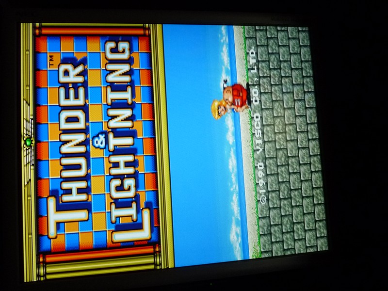
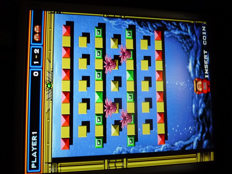
Got a Thunder & Lightning, a nice ball and paddle game from Seta on the bench today.
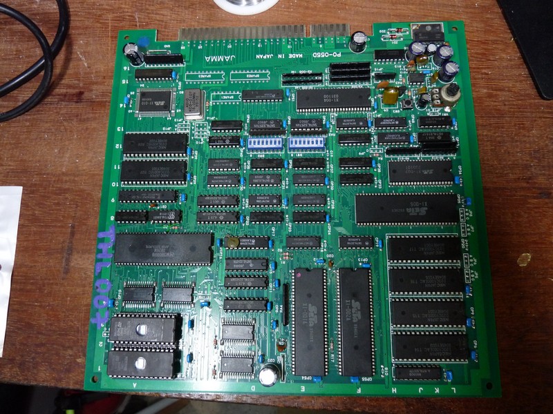
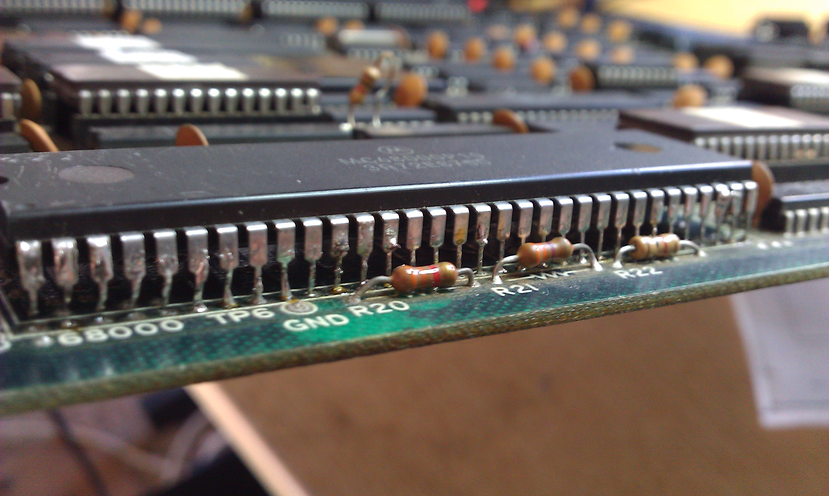
At first glance the board looked fine, but there was some worrying rusted pins on one LS close to the 68000 … not sure why, but other chips around weren’t affected.
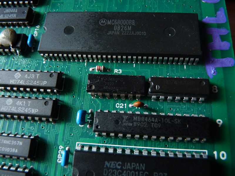
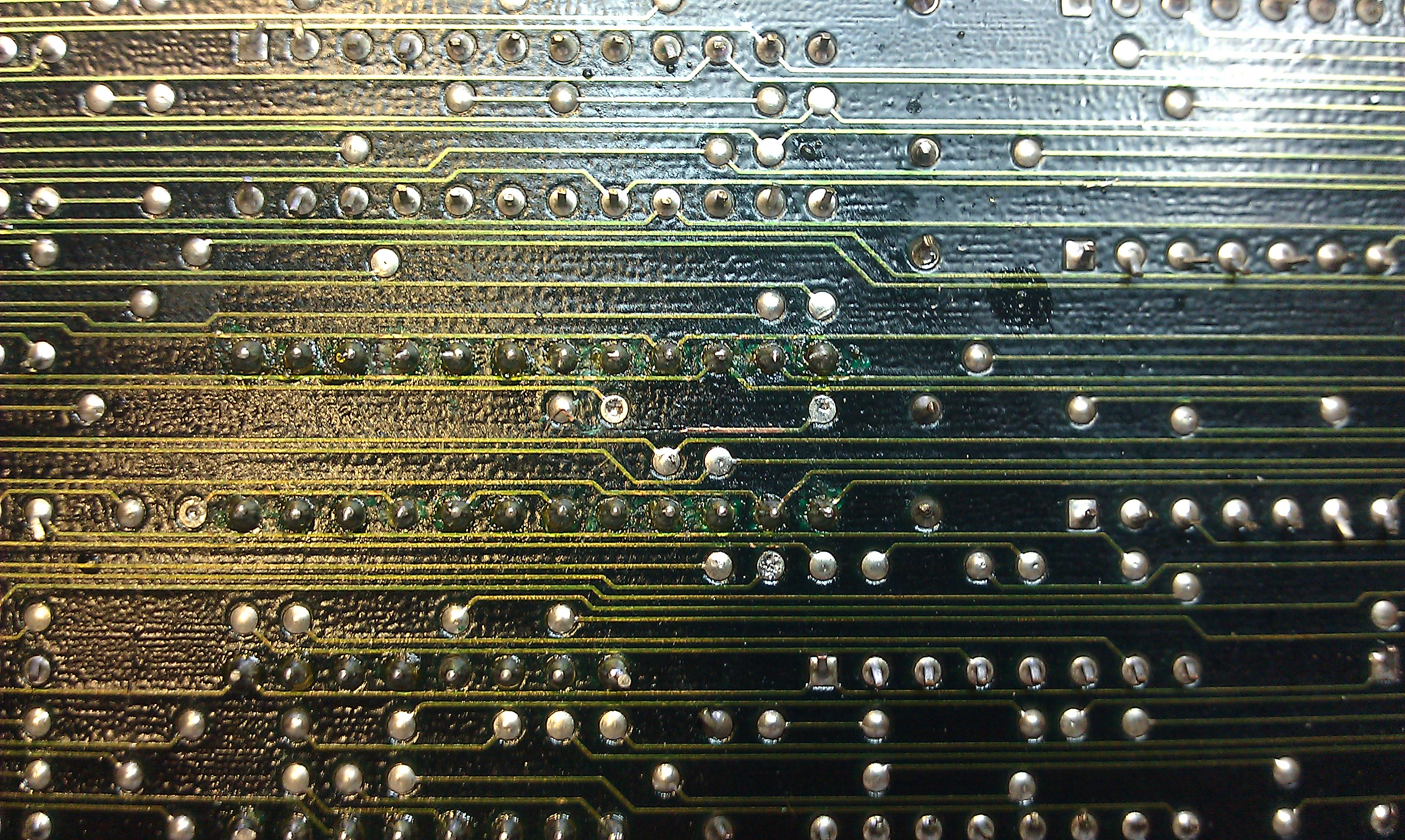
I replaced the chip and patched the traces with some kynar wire.
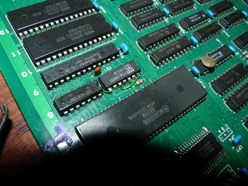
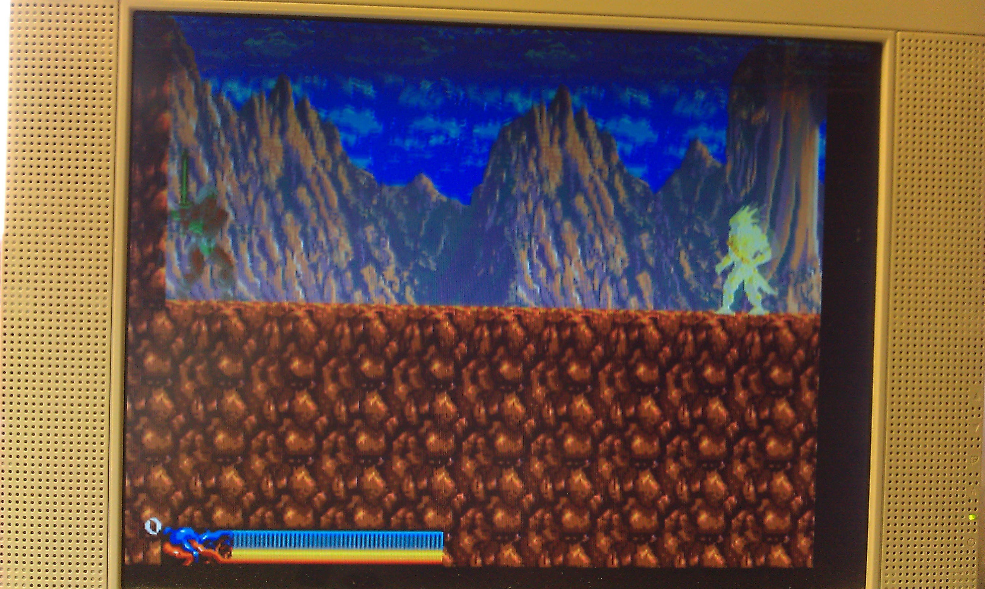
When powered up, a working game displays a moving patchwork of tiles for a few seconds before displaying the title screen. In this board case, the tiles patchwork was displayed, but it kept rebooting just before displaying the title screen.

On this board, dipswitch 1 of the first bank puts the game in test mode. Doing so displays a color grid, and after pressing a button you get to the input test. The board worked flawlessly in test mode, meaning the main CPU worked enough to run it. But when pressing the reset button on the board, the following message started to show: “Address Error 2020E6”, before rebooting again …
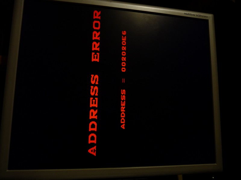
Not knowing where this address pointed to, I looked into Mame to find the memory map of the game. And I found something very interesting : a PALCE is used as a protection device, using some address lines as inputs and computing a value that’s grabbed later by the CPU … if the value isn’t the one expected, a soft reset is done. That looks reaaally familiar !

Here’s the offending chip (TL-9) :
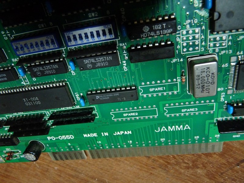
It was removed …
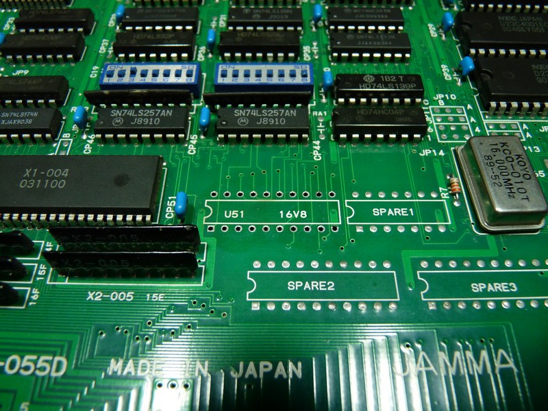
.. and replaced by a GALV16V8, using the file from the PLD archive. I added a support just in case.
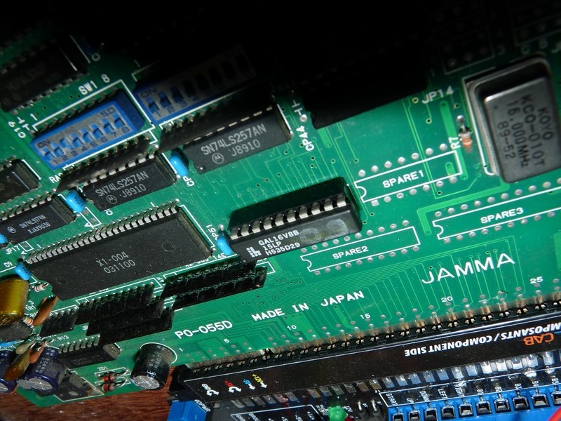
And voilĂ  !

Played a few levels to be sure nothing’s amiss, all is good !

Rastan repair log #1

 PCB Repair Logs, Repair Logs  Comments Off on Rastan repair log #1
May 022011
 

Very nearly gave up with this one thinking it was a custom IC fault, glad I never.

Was sold this board as a non worker, the guy said it boots to a white screen and the CPU needed to be looked at.
He was right on both counts.

image
image

Before I did anything that CPU needed socketed. Once I had done that I fired the board up again but got the same white screen. I checked the data lines of the CPU and they were dead. I initially tried a known good 68000 CPU but this resulted in the same screen.
There are 6 ROMs next to the CPU which are the program ROMs. I pulled all these and checked them against MAME. The first 3 checked were fine the last 3 were actually from an Operation Wolf board and 2 of those were dead anyway. Burned 3 replacement 27c512 EPROMs and tested again.
This time I got a white screen with some garbage on.
After this I plugged in the Fluke 9010 and ran some ROM and RAM tests. The ROMs passed fine but one of the RAMs had failed. The TMM2063 @ IC10 was shot, I used a D4364 as replacement as its the first one I found compatible on a scrap board.
Board still booted with garbage.

image

All lines on the CPU had frozen.
Checking the game running in MAME I could see that when you first boot the game the whole screen flashes white for a second then the game boots.
I checked the 3 Interrupt line, IP0, 1 and 2, and found that IPL1 was dead, this came from a nearby PAL @ IC36. The PAL was giving an output so I ran a jumper wire to the CPU and booted again.
This time I got a full white screen with the Hi Score at the top and the game ran but only showing the sprite data.

image
image

I checked all the ROMs that hold the background data and they all checked out fine. These are MASKROMs and can be read as either 27c301 or a couple of reads as 27c512 with a small modification.
Following the data route from these ROMs I eventually came to a 74LS157 @ IC72. It had dead pins at #3 and #11. Pin 3 should go straight to +5v and pin 11 should come from address bus A10. Ran a couple of jumpers for these and got something a little different, the screen was still mainly white but I could see text underneath it and the sprite colours were now messed up.

image
image

Looking underneath the board I found a discoloured track, when I ran the screwdriver over it, it came away from the board looking a little charred.

image

Only a short jumper required but it was underneath the palette RAM. I started checking the palette RAM and found pin 16 was dead. I removed this 2018 RAM @ IC73 and it tested faulty, replacing this with a 6116 brought the graphics back fully.

SEGA ST-V repair log #1

 PCB Repair Logs, Repair Logs  Comments Off on SEGA ST-V repair log #1
Apr 282011
 

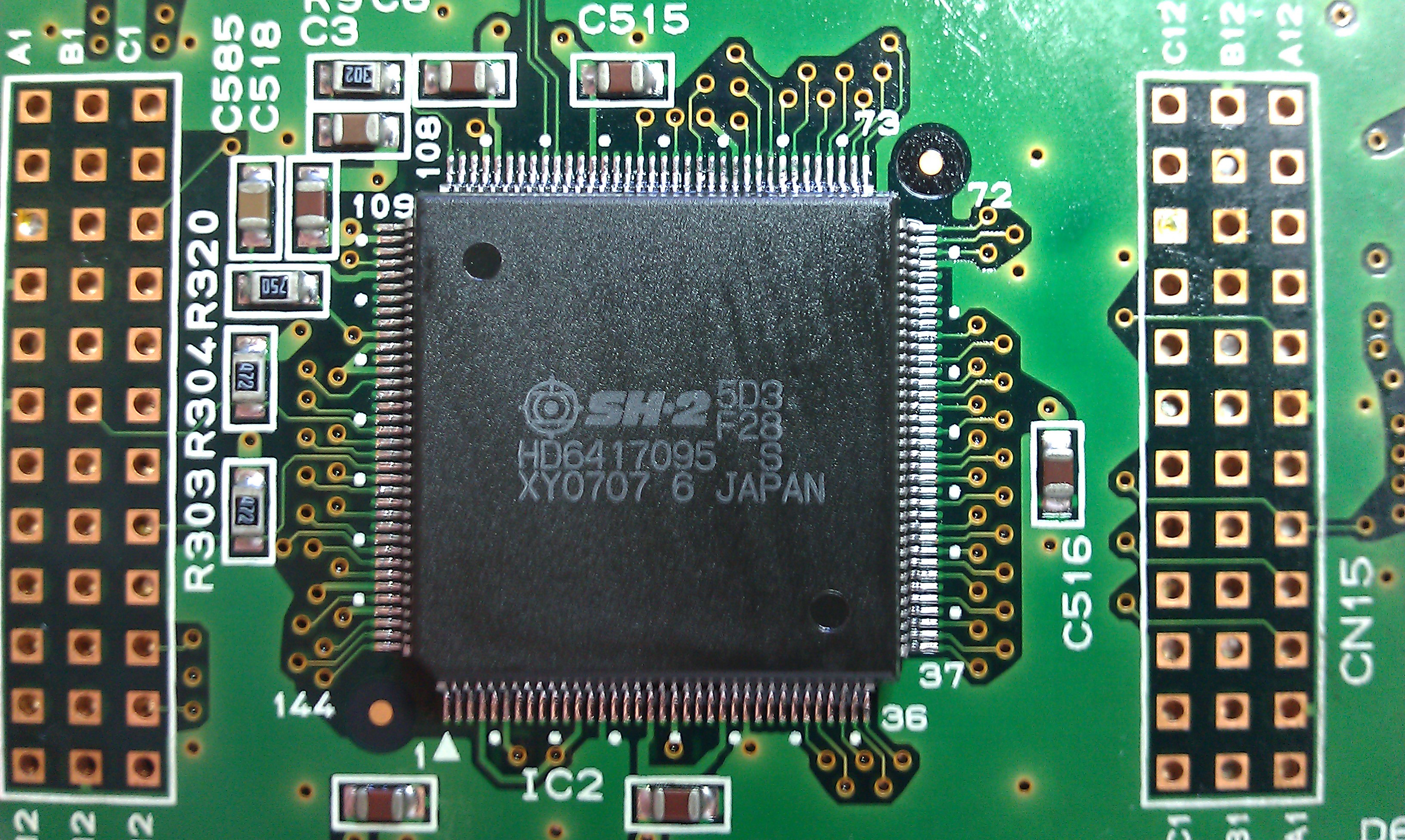
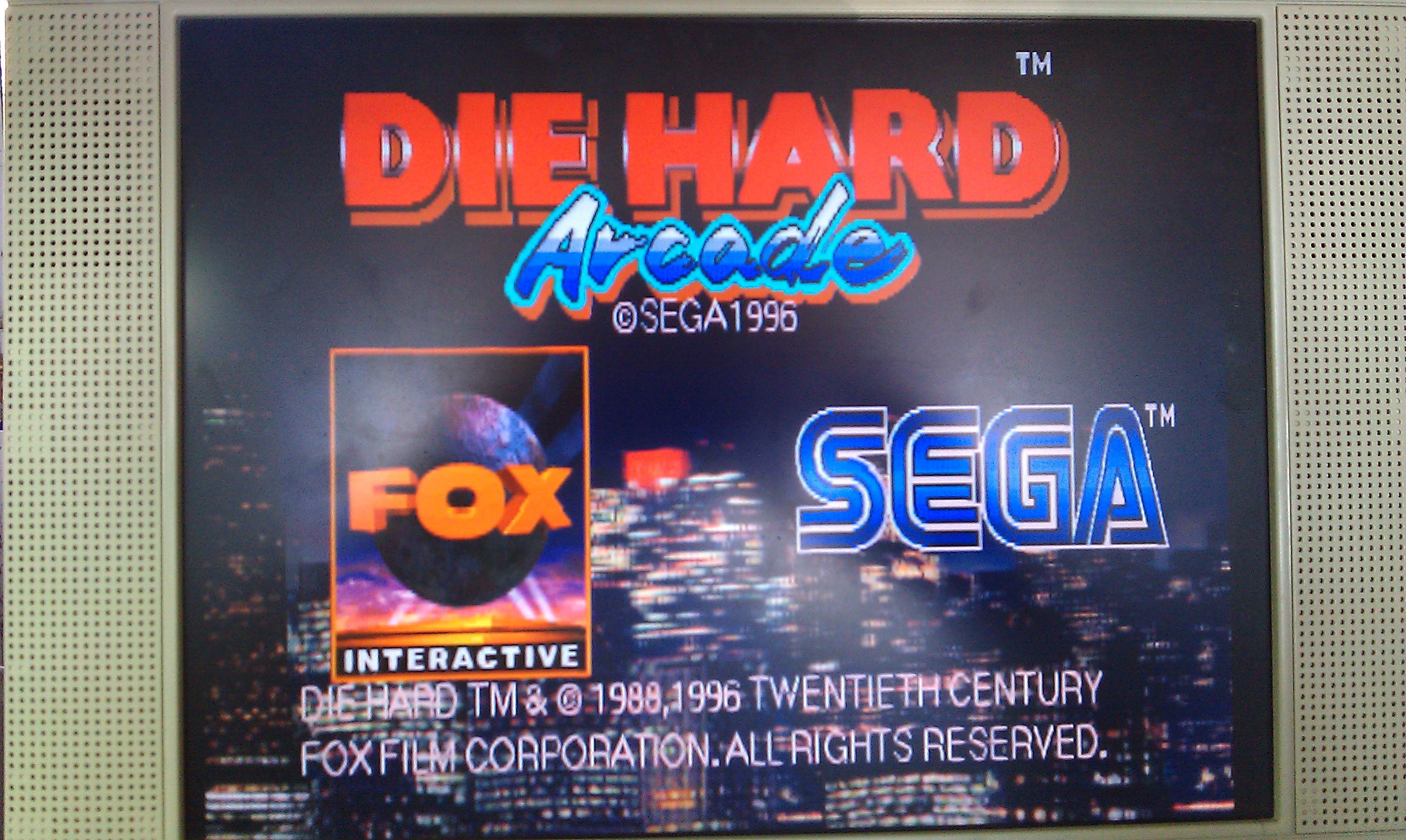
First repair from the lot I recently got. Sega STV motherboard with Die Hard game.
When booted up with no game cartridge the board passed all it ROM and RAM tests. With a cartridge inserted the board crashes after the copyright screens. All the cartridge tests also came up as being good.
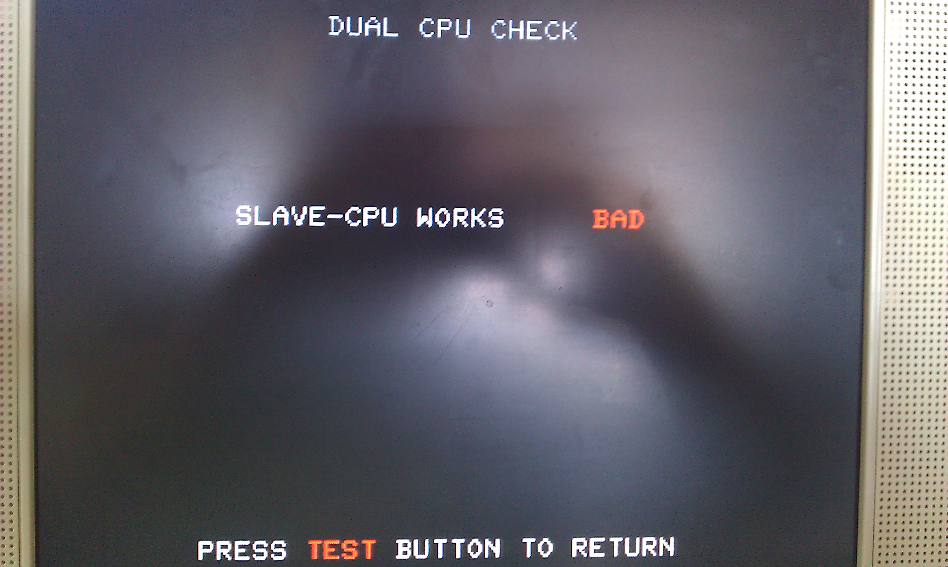
There is a developers test menu that is accessed by holding the TEST button down on power up of the board, this gives you access to a whole host of extra tests, one of them being a Sub-CPU test. Running this test flagged it up as being BAD and the board locks up.

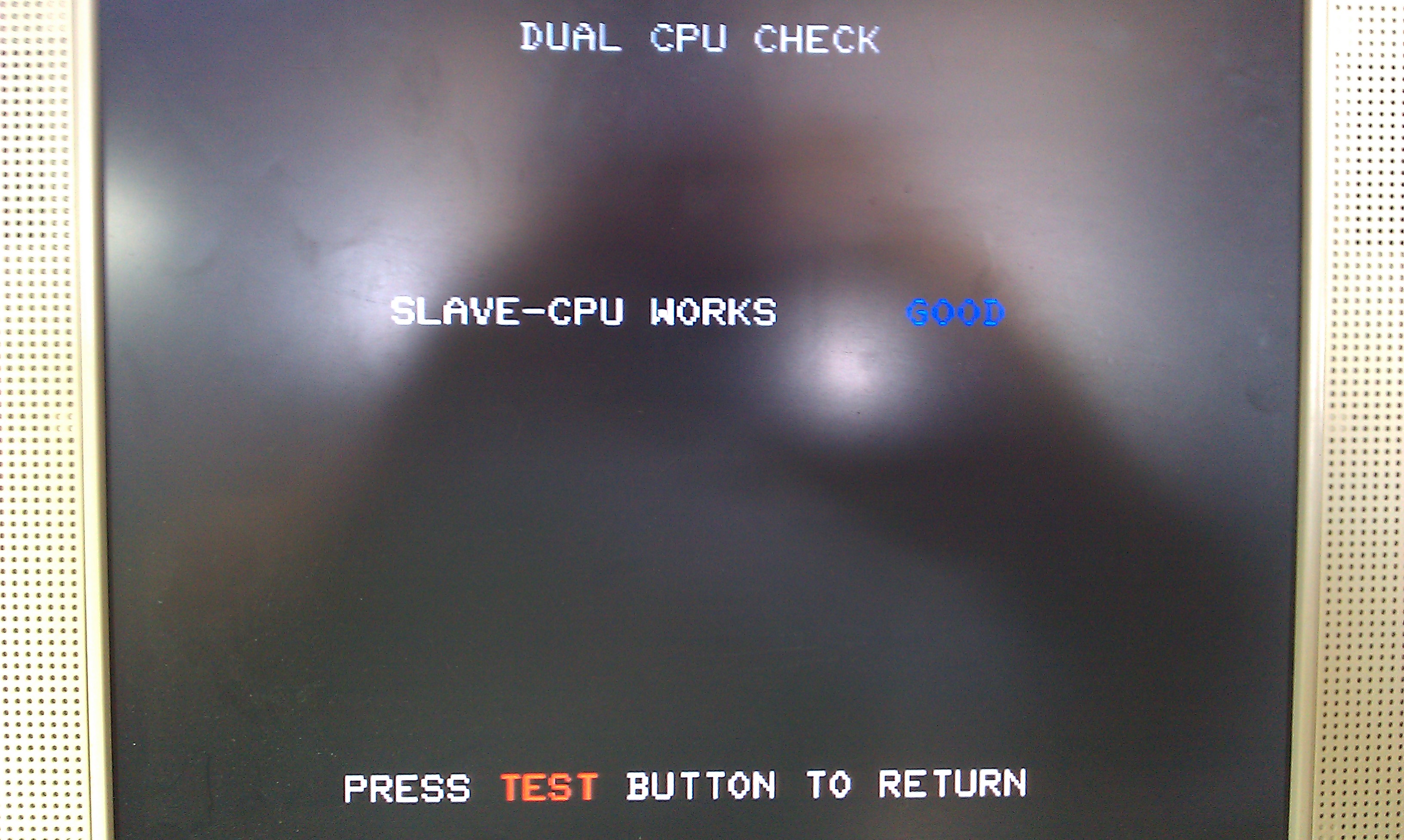
If I pushed down on IC2 (this is the Sub-CPU, an SH2) the board would pass its test.

This fault seems to be very common on STV motherboards and is easily fixed by reflowing solder on all the pins on the SH2 processors. I did both of them for good measure and the board now passes all its tests and the game boots up.


Not played this game before and its actually quite fun, like a mashup of Virtua Cop, Virtua Fighter and a little bit of Shenmue thrown in for good measure, it would make sense as the STV hardware is based on the Sega Saturn (or vice versa?).

CAPCOM Commando repair log #3

 PCB Repair Logs, Repair Logs  Comments Off on CAPCOM Commando repair log #3
Apr 162011
 

Whilst soak testing the Commando board I had recently repaired for someone 2 bad things happened.
First the music disappeared
Second the pictures vanished.

I checked the RGB outputs with the scope and the signals looked a little weak but should be fine. I checked the SYNC signal and this was stuck HIGH.
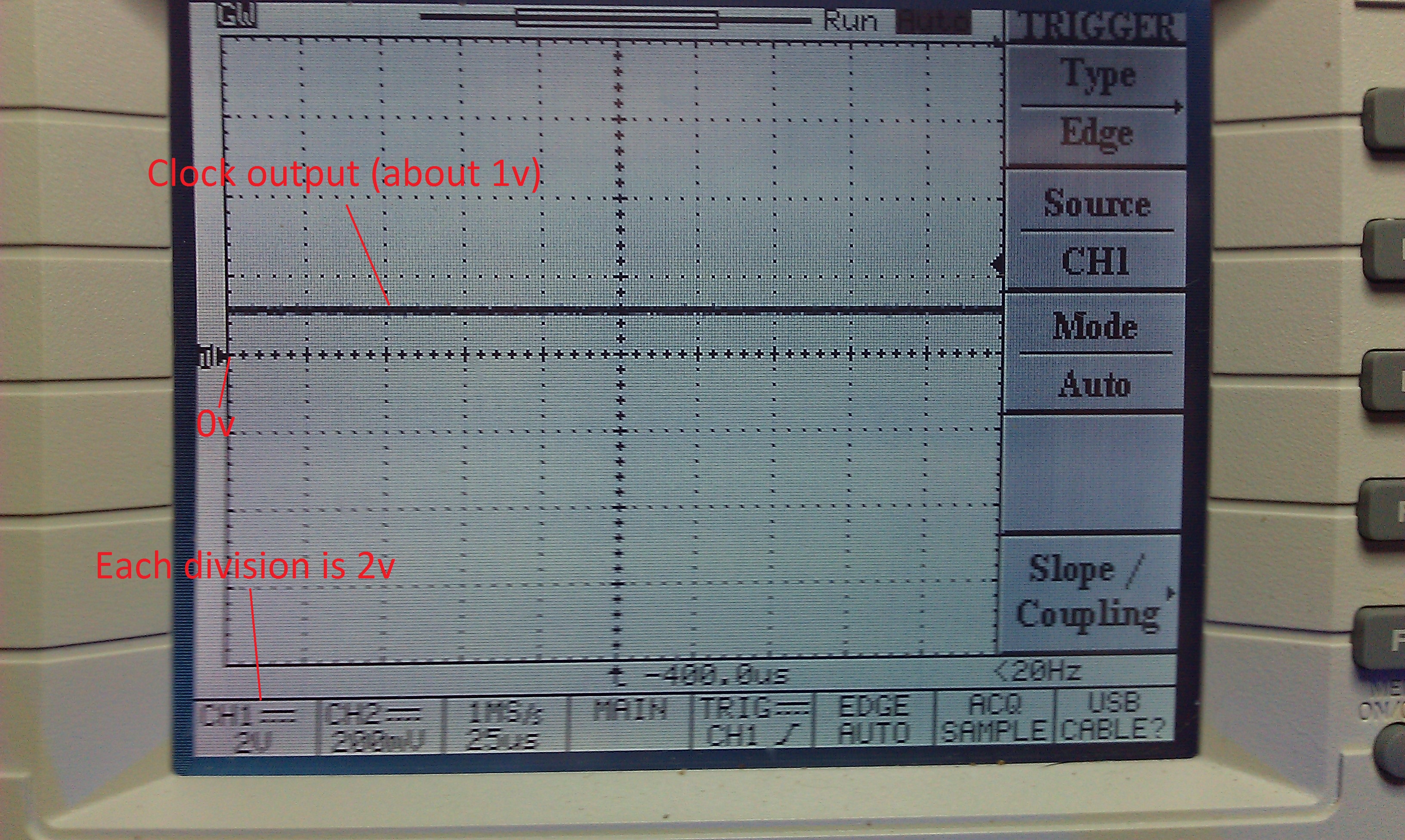
Followed the signal back from the edge connector to a 74LS138 IC @ location 5L and the outputs on pins 3 and 4 were both stuck at just under 1v according to the scope.

The inputs to the IC were fine. I piggy backed a working LS138 and the picture came back normal.

The sound fault was fairly simple too.
The first thing I did was check the RESET and HALT lines on the Z80 CPU. These were fine and not stopping operation. Next I checked the clock signals on the Z80 and the Yamaha 2203’s. The Z80 was fine but there was nothing on the 2203’s.
The clock signal for these 2 come from a nearby 74LS74 IC who’s outputs were obviously dead but all the inputs were “as schematic”. I pulled this and testing it, it failed and a replacement has restored the sound fully.
Finally this is in good health once again and hopefully it will stay that way for a while longer, although with the amount of Fujitsu TTL IC’s on the board I very much doubt that but it is 26 years old now!

CAPCOM Commando repair log #2

 PCB Repair Logs, Repair Logs  Comments Off on CAPCOM Commando repair log #2
Apr 102011
 

Got sent a Commando board for repair a while back and have finally got around to giving it a test.
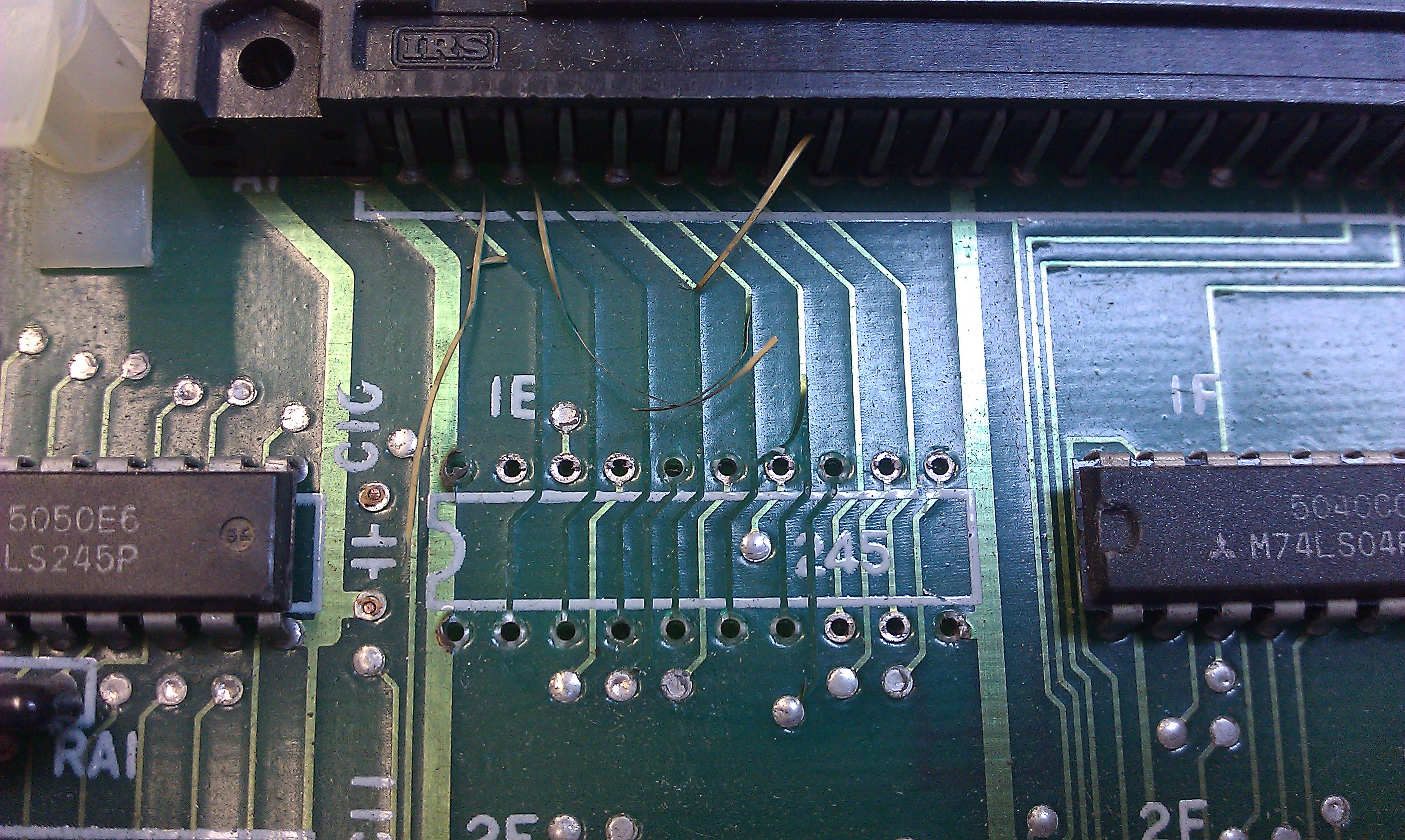
I spent a little time going over the board doing the visual inspection prior to booting up. On the bottom board a 74LS245 had been removed and was just sitting in the board loose but most of the traces going to the IC had also been lifted, I suspect during a bodged removal.

image

I refitted the IC (after testing it), cut the lifted tracks off the board and ran some kynar to the relevant points.

After spending a bit of time making another adapter up to run the game I saw the graphics fault.
All the sprites were barely visible and sometimes were gone completely.
There was also some corruption on one of the screens.


The manual for this game is online and in the back of this are the schematics for the game. Nice. Also, as its CAPCOM, the schematics are nicely split and labelled up in sections.
After seeing the fault I was convinced that RAM was to blame. I scoped a section of 4 x 2114 RAM chips on the lower board. All had good looking address lines but the data lines looked very odd like they were struggling to drive the lines low. I interrupted a couple of pins and graphics started to come back so I pulled it and testing it, FAIL. One replacing the RAM only half the sprites came back with jail-bars running through them. I ended up pulling 3 in total which was quite lucky as I ran out of RAM replacements.
All graphics are now returned to normal.

As for the corruption on the screen. Thanks to MAME I was able to determine this to be an unused part of the screen that my RGB to VGA converter decided to throw in there to confuse me. In a cabinet the screen would be adjusted to remove these borders.