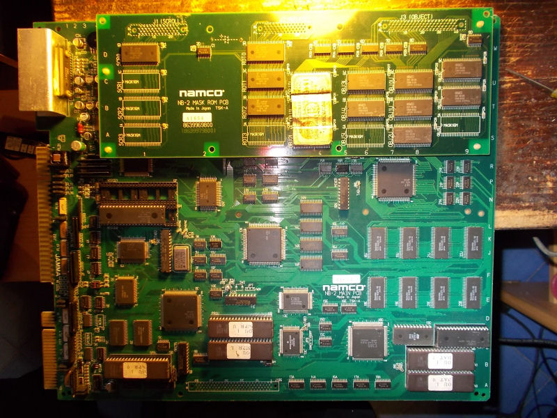
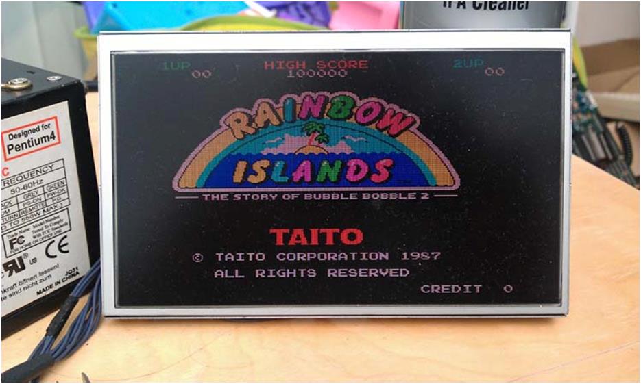
I was fortunate enough to obtain an original Taito Rainbow Islands PCB recently, which of course was not working.
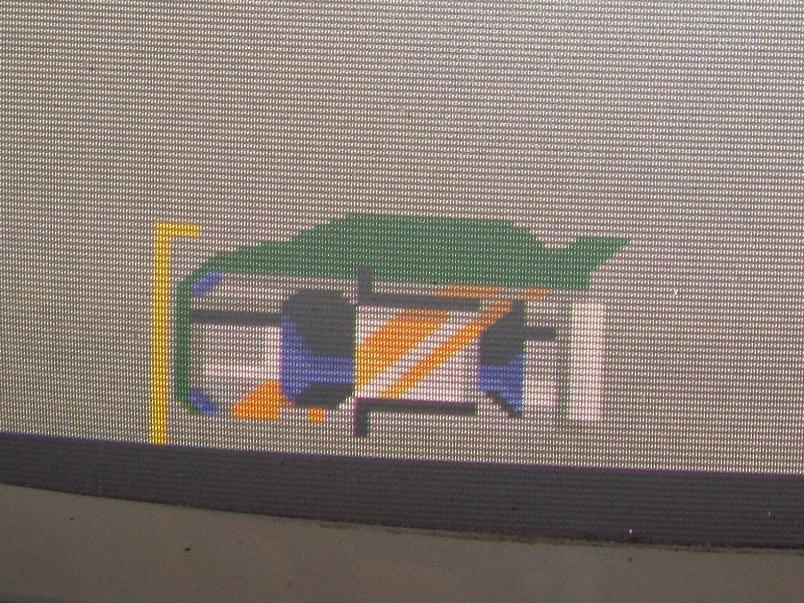
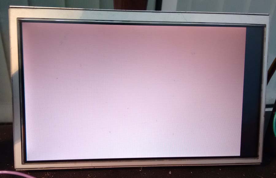
I tested the PCB in my Supergun and was presented a solid white screen;
Checking the 68K CPU, the clock was fine, and RESET line was held high, there was activity around the CPU which indicated it was trying to execute code.
The work RAM looked good, so I checked the two 62256 SRAMs that the PC080SN custom uses for all backgrounds/tiles. The outputs looked bad on both. I also noticed that when I touch the pins on the SRAMs the screen display changed.
I removed the SRAMs (IC3 & IC4) and confirmed they were bad in a RAM tester.
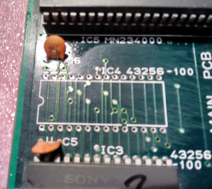
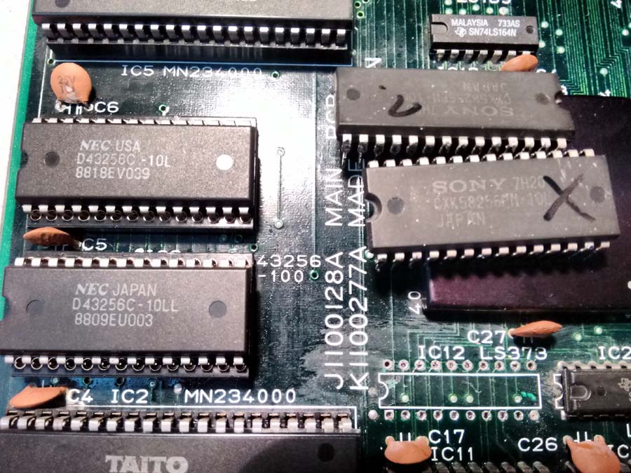
I installed sockets for easy maintenance and replaced with fresh SRAMs;
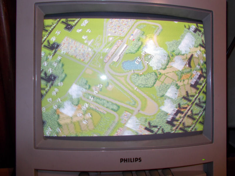
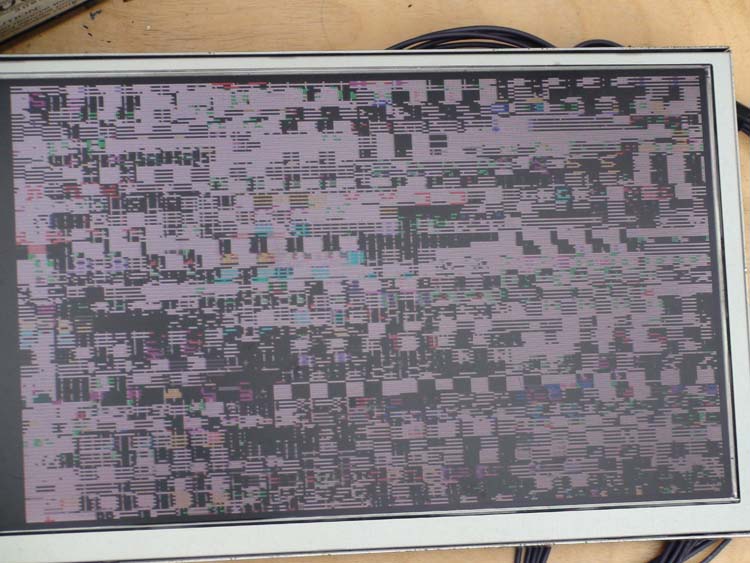
The PCB was now running, but had some issues with background/tiling;
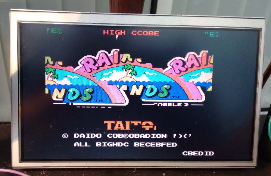
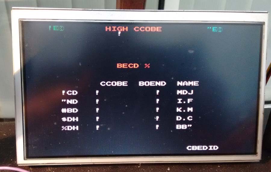
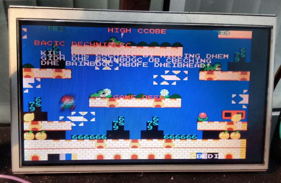
Speaking to my friend Porchy about this fault, he stated that it appeared that Bit 4 (counting from 0) was stuck LO, and that the PC080SN custom was responsible for it (RAM lies at address 0xC00000 – 0xC0FFFF).
I was hopeful it was not a fault within the custom, and eventually after probing found that IC12 (74LS373 Octal Latch) Pin 9 was stuck LO (should have been pulsing LO/HI).

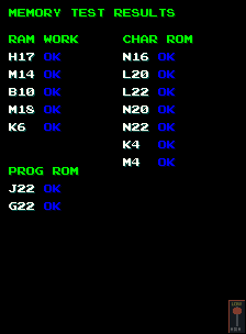
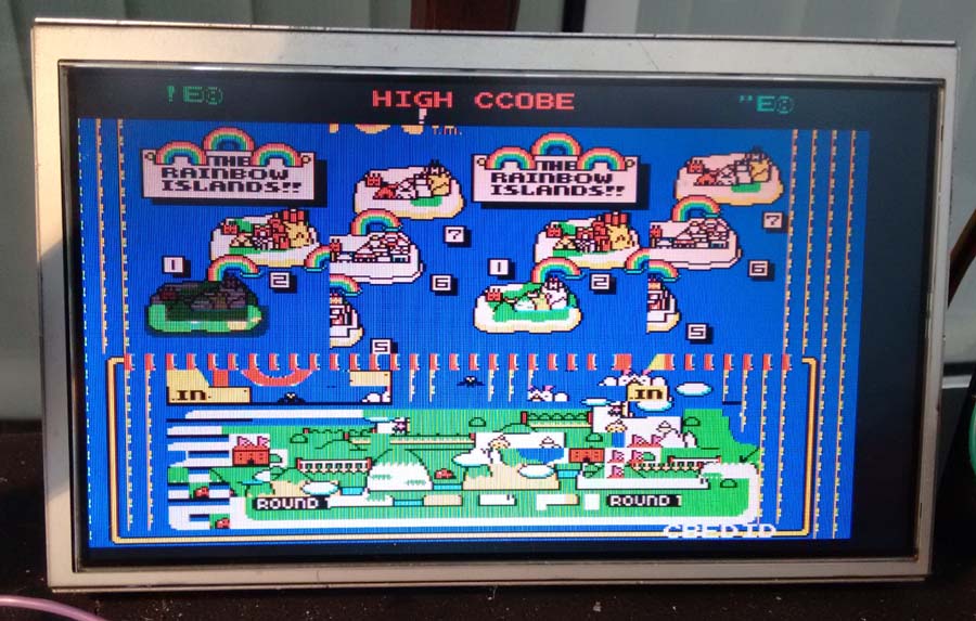
I removed the IC, installed socket with fresh 74LS373 and was greeted with a fully restored display;
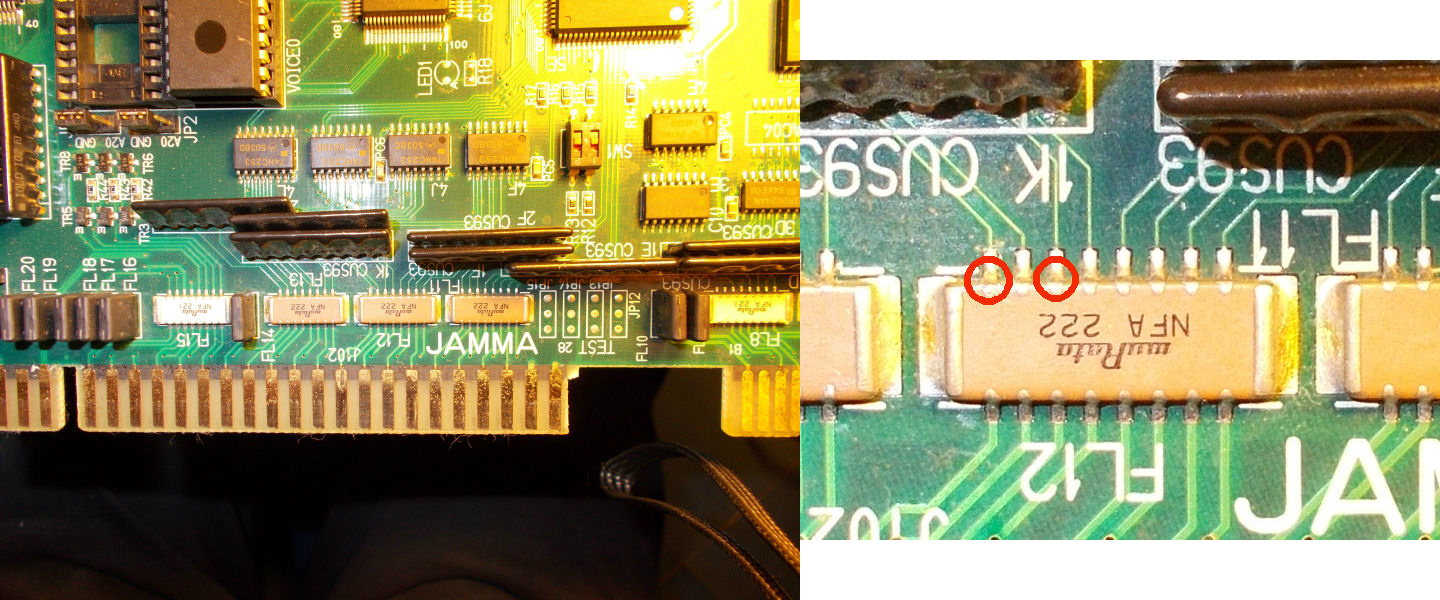
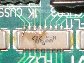
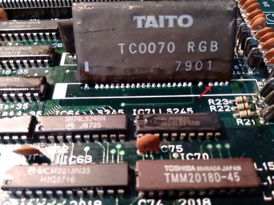
I did notice however that sometimes the display would lose all the BLUE. So my attention turned to the TC0070 SIP custom that handles RGB. I found a cracked pin (highlighted with Red arrow), which I resoldered to resolve it;
It was now running perfectly, except for the sound which appeared to be absent totally.
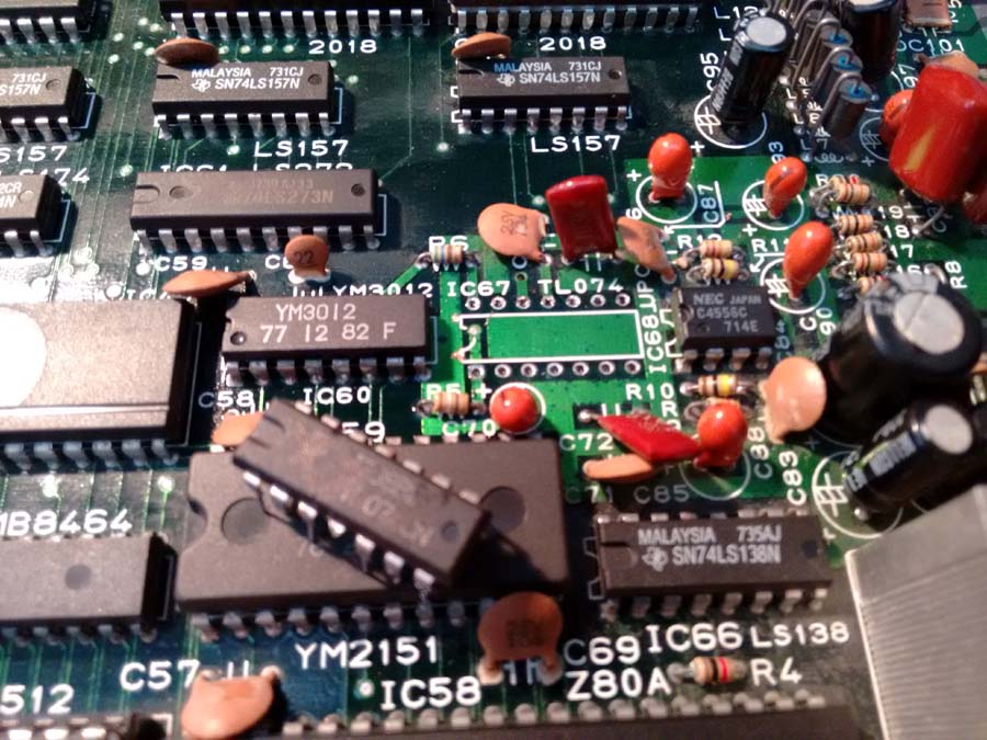
I checked the Z80 CPU which handles sound, and it was definitely running code. So I checked the TL074 op-amp at location IC67 and found it appeared dead (no output, but probing input I could hear the sound!). So I removed it, installed socket with fresh TL074 to fully restore the sound;
Many thanks for Porchy for his help with this repair.
Another Rainbow Islands Log to come very shortly, solved with help from my new friend Caius.