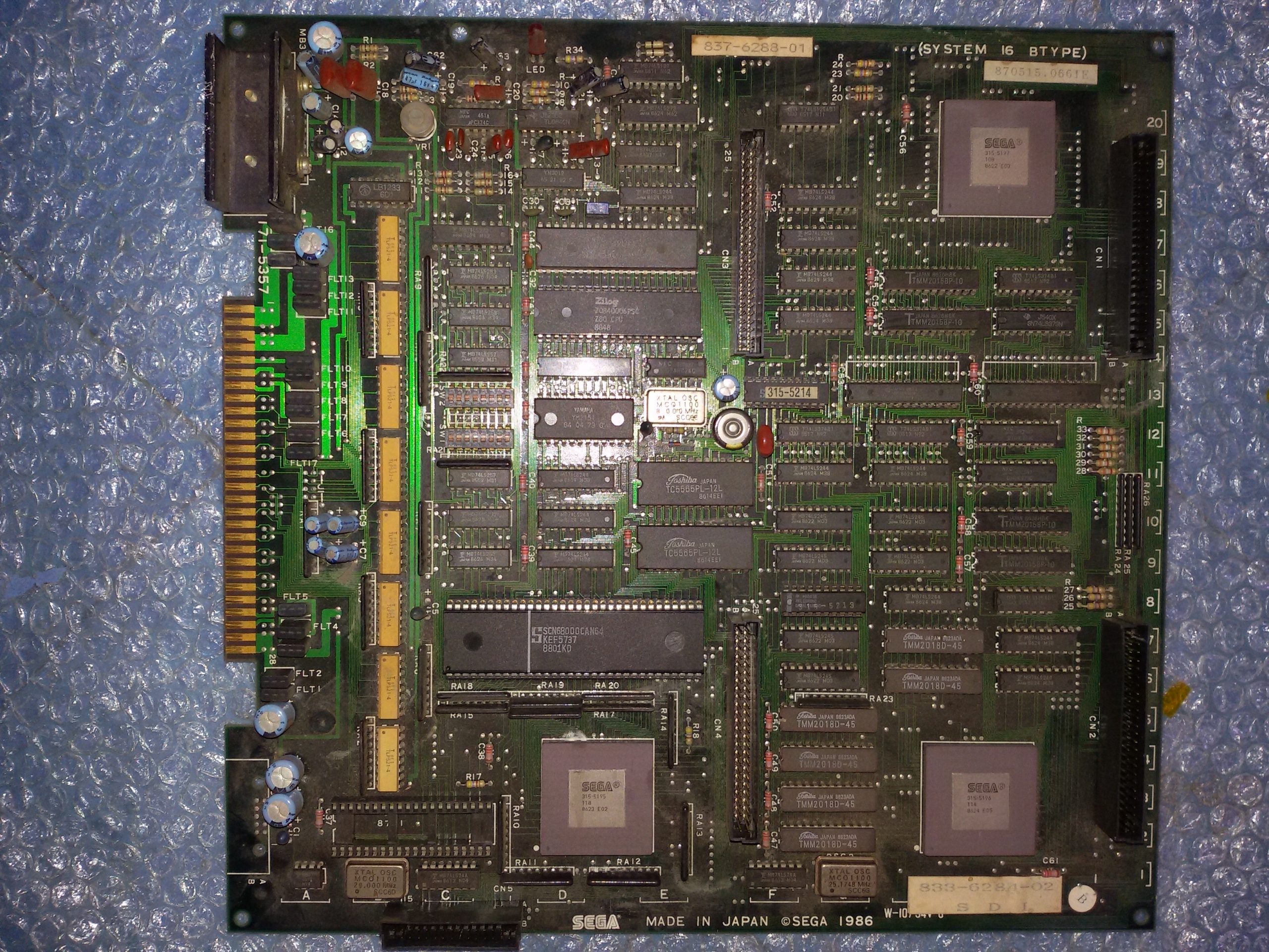
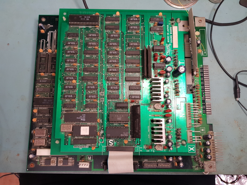
Got a familiar Operation Wolf PCB that I offered to look at for a friend.
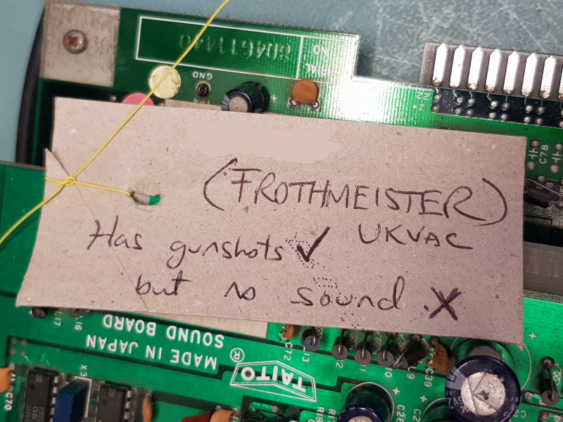
I’ve had this board several time over its life and this new fault was “no sound”. The sound actually stopped working when the owner hit the start button but the game could still be played.
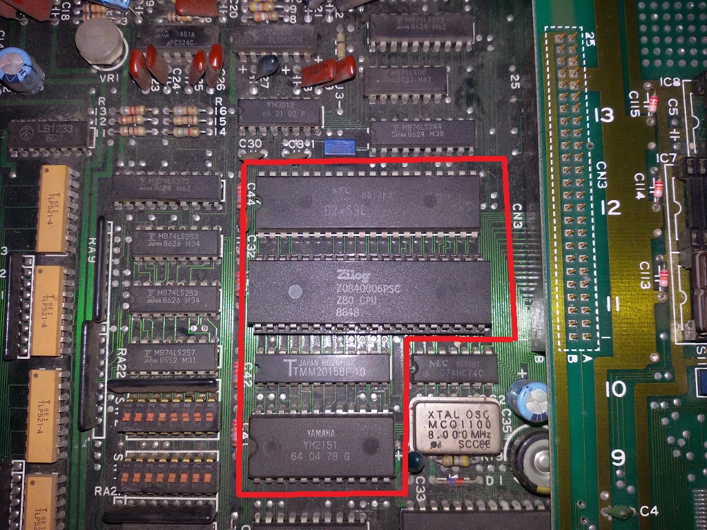
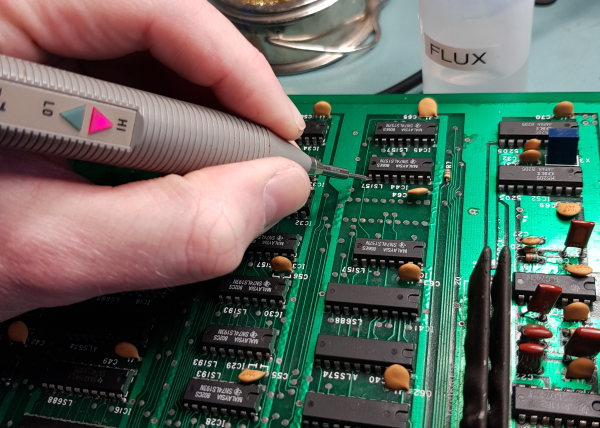
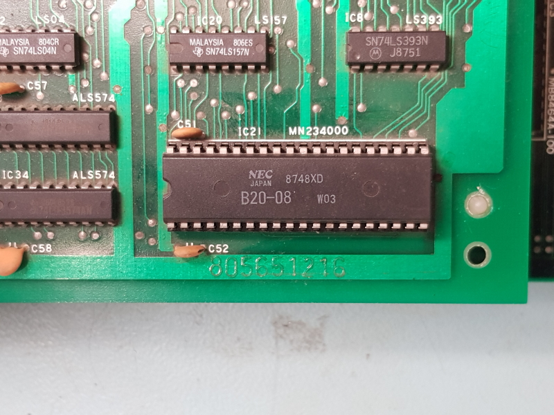
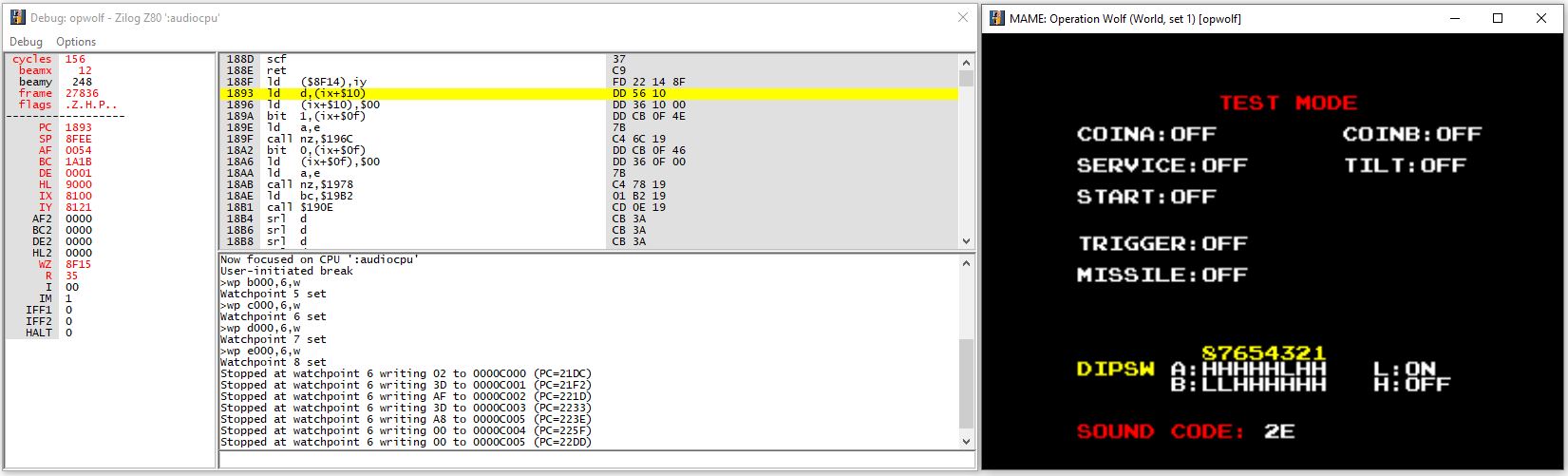
I found the fault really quickly. Starting at the CPU I checked all the signals on the Z80.
Everything was doing what it should be doing except for the /NMI pin (pin 17) which was stuck high all the time.
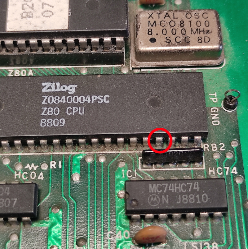
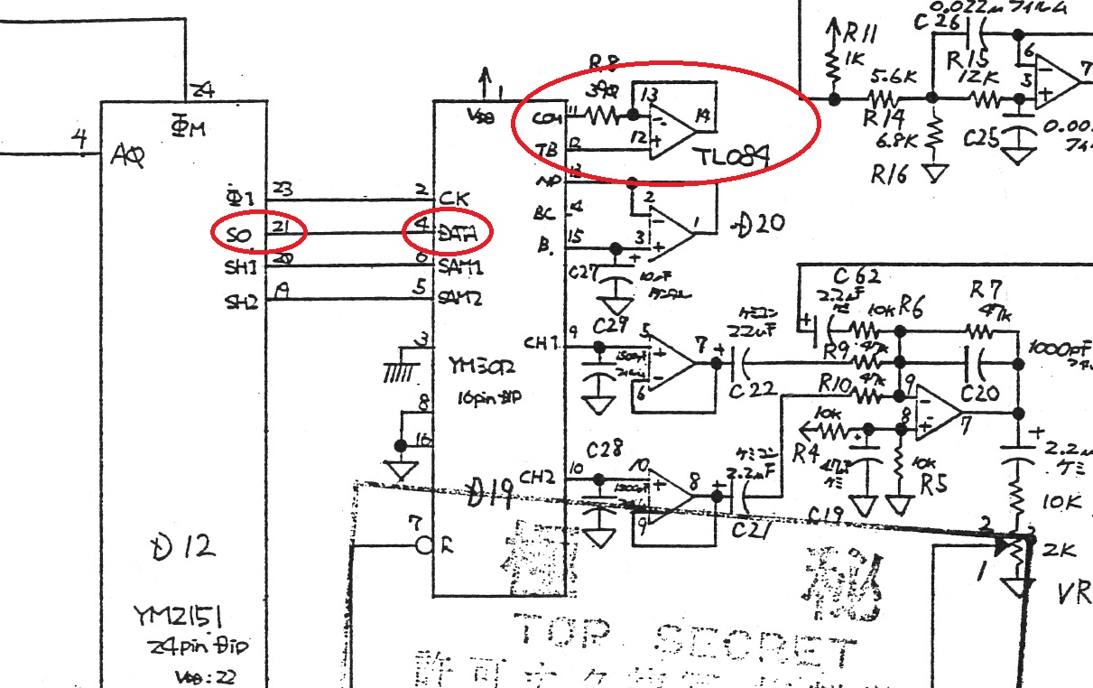
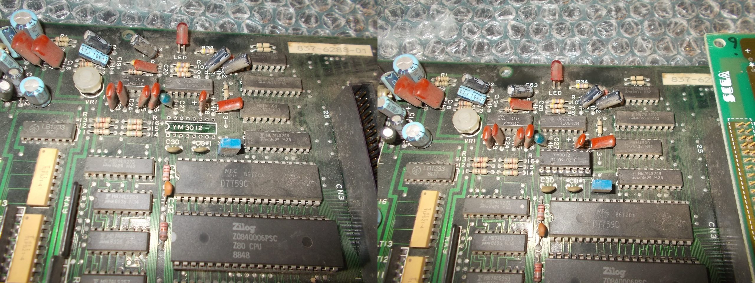
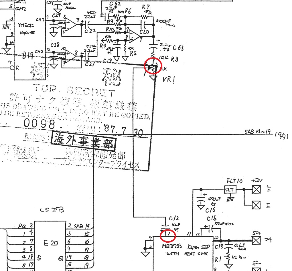
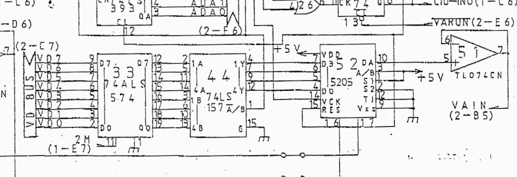
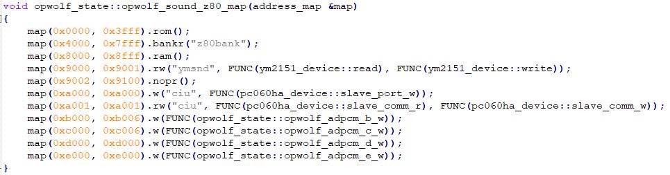
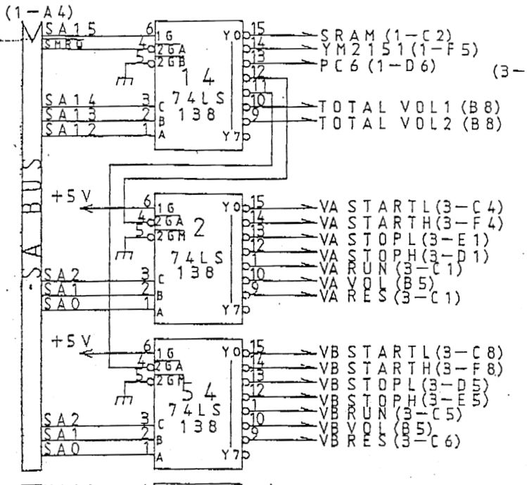
The NMI is used to signal to the sound CPU to start playing a sound. The signal is generated by the custom PC060 chip nearby on pin 12
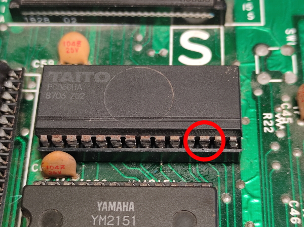
I transplanted the custom from my Rainbow Islands PCB to test and the sound all came right back.
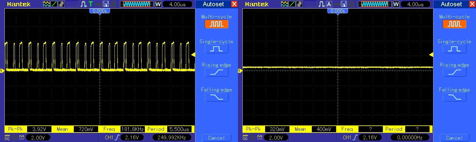
Here you can see and hear the /NMI pulse as a new sound plays
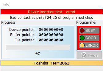
So now I’ve confirmed the device at fault what do I do for a replacement. I have no scrap boards with one available. Furrtek has recreated the operation of this device and Caius has made a CPLD replacement that uses this code.
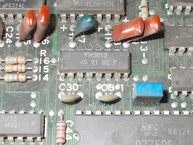
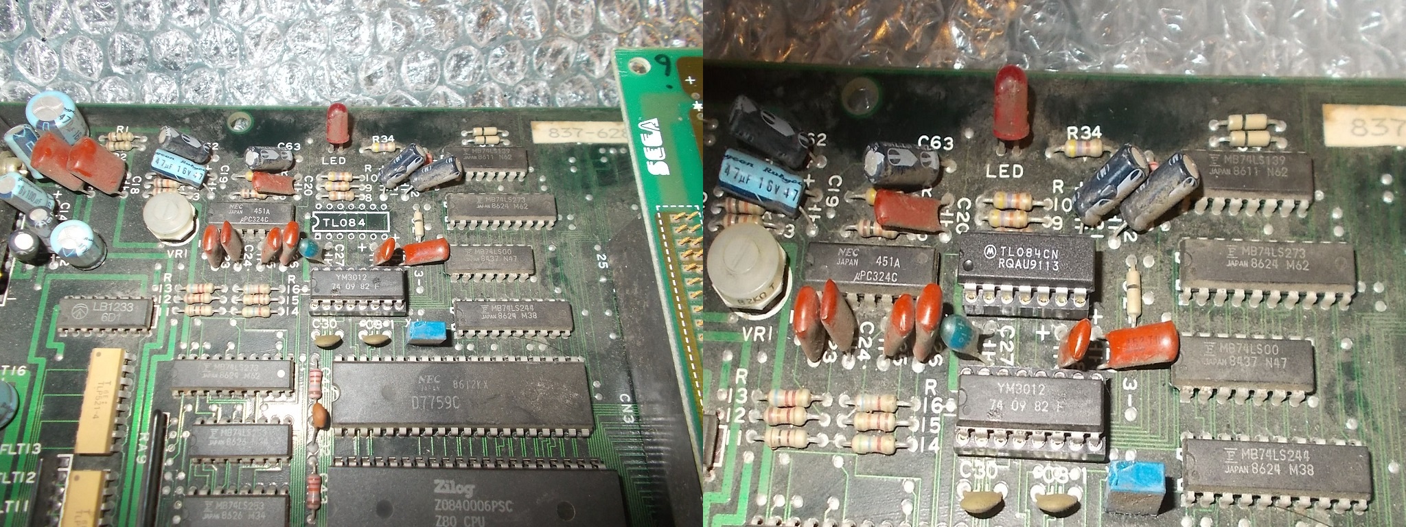
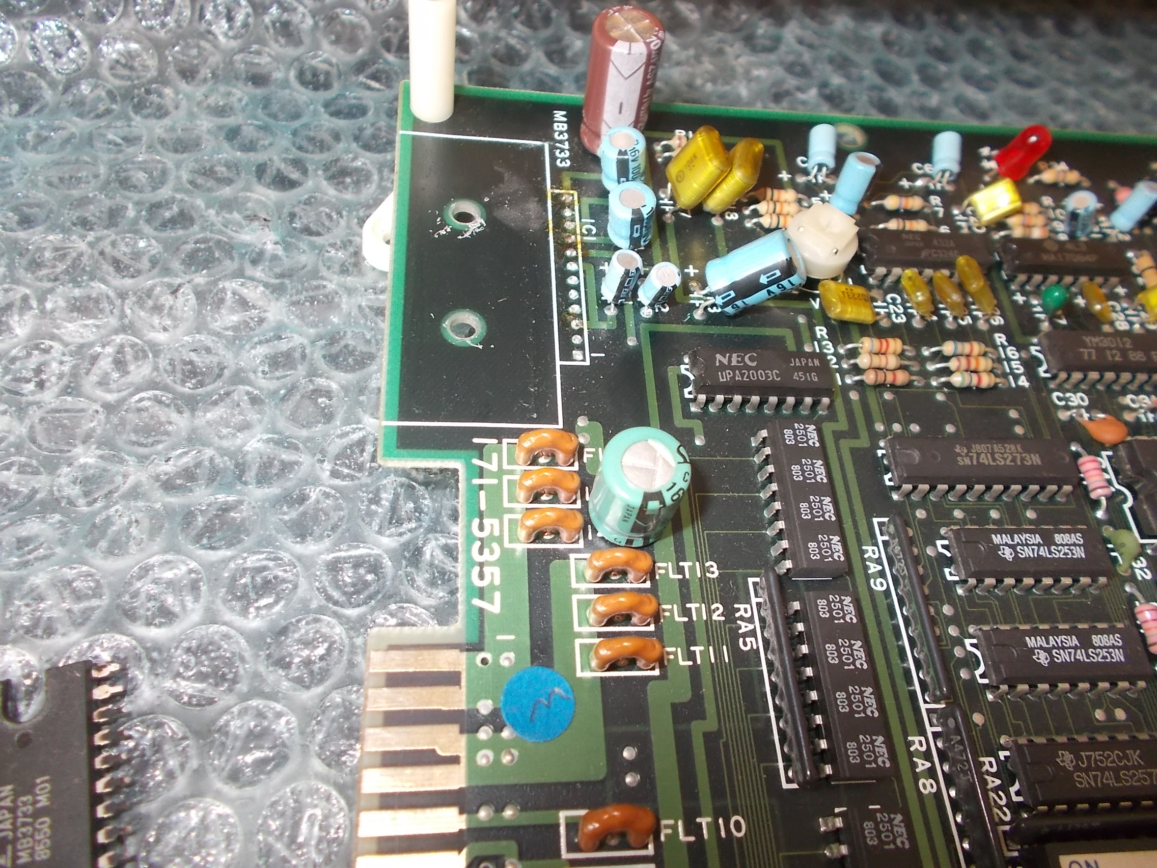
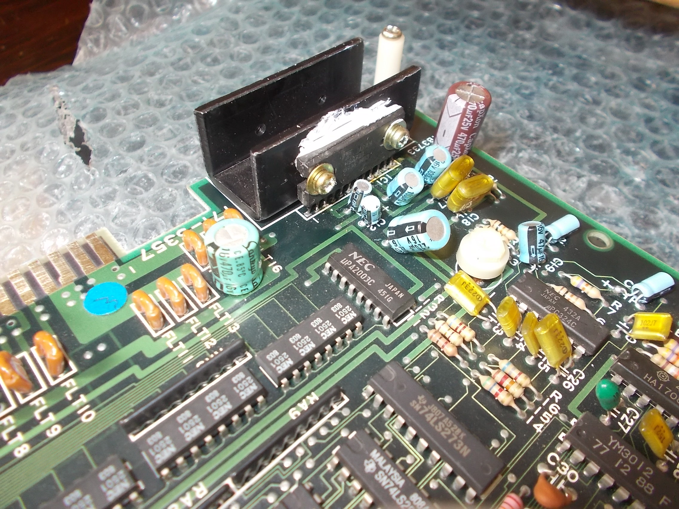
I’ve recapped the sound section and Caius is sending me a replacement but for now I’m happy that this is working again.