
Another board from Mr Muddymusic and this ones a pain.
It was reported that this one has a short and sure enough when I checked resistance between GND and VCC I got pretty much a short
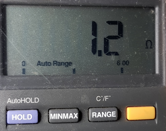
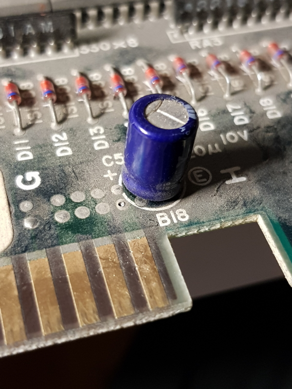
Using a Polar Toneohm micro-ohm meter I quickly found that the capacitor next to the edge connector had a lower reistance than at any other place on the board. Removing it cleared the short.
With that clear I could fire the board up and it was dead.
Checking the 68000 CPU I found I had a dead clock input.
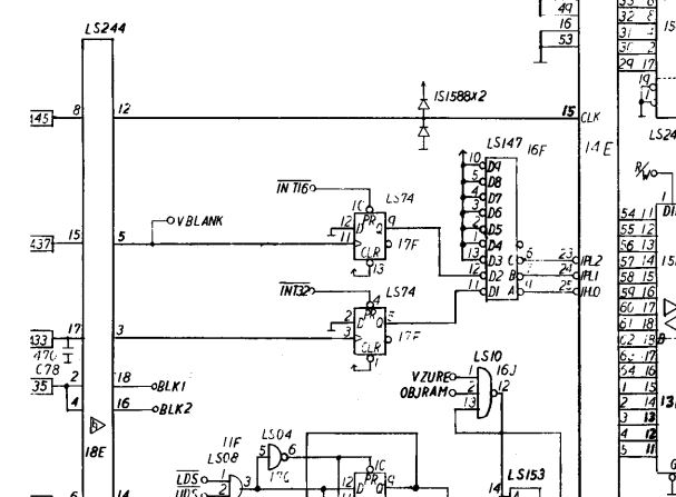
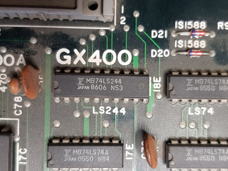
The clock comes from the lower PCB and using the schematics show it coming in through a nearby 244.
Replacing it gave me my clock back but now we have some watchdogging.
Again I probed the CPU but all seemed fine so moving out I started checking the line drivers and buffers on the address and data pins until I came to a 74LS244 @ 15F with dead outputs.
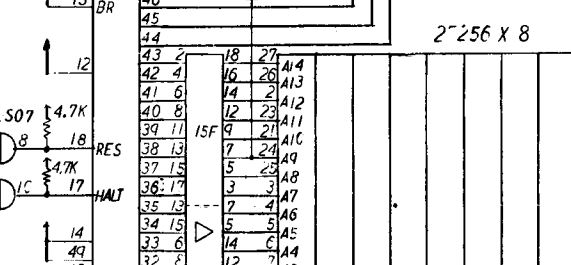
Replacing this gave me a kind of booting game
Watching MAME run through the game it seemed to me that this was getting to the screen where it displays the POST results and then hangs. I confirmed in MAME that if a test fails then the board will hang at this screen.
I pulled all the ROM’s and they all checked out good so I turned my attention to the RAM.
The main RAM appeared to be good so I moved on to the other RAM that gets checked at startup.
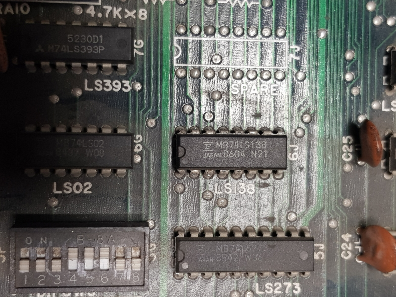
The schematics show a 138 used for selecting different RAM. I found pin 15 was very weak
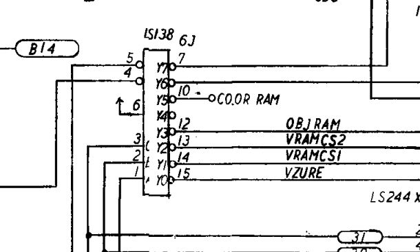
The enable was now fixed but it didn’t really change anything
As all the chars were a mess I decided to start looking at the character RAM section.
After a bit of probing I found that all the address lines to the 4416 DRAM’s were stuck high a lot of the time. I traced these back to another 244 over in the top corner of the CPU board.
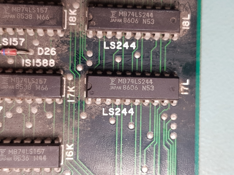
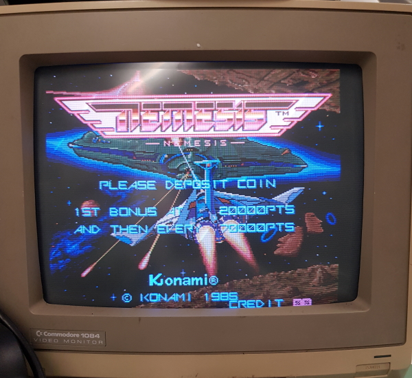
Finally I had a booting game.
Instantly I see the colours are off and the sound doesn’t work. Starting a game also revealed the game started itself on coin up and I was unable to control anything. The ship also fired on its own.
Time to boot into test mode and see what was going on.
Test mode is invoked by switching DIP 3 on DIP bank 3 but the game just booted as normal.
I confirmed the switch was actually working using a multimeter but somewhere along the line it was going missing.
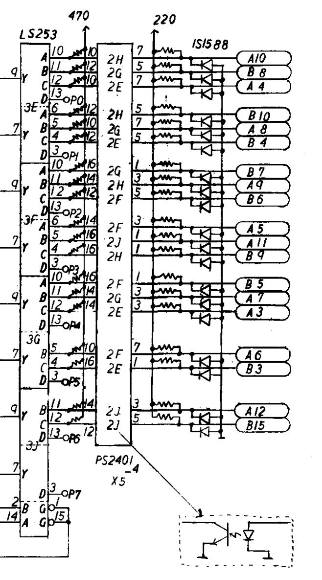
I traced it back using schematics to the 253 @ location 3F.
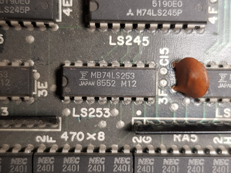
As the outputs of this chip are on the databus I struggled to see if it had real outputs or not so I just opted to replace it and it paid off, I could now access test mode
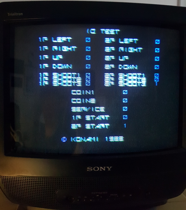
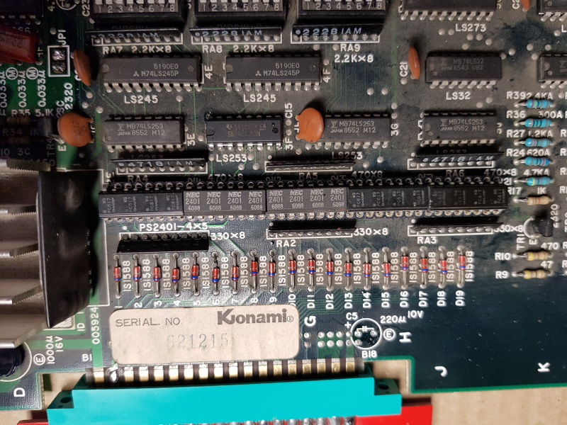
A couple of buttons seem to be stuck. Long story short all of the PS2401 octocouplers had some issue on one way or another so replaced them all with ones I found on a few scrap boards
Next, the dodgy colours.
Looking at the schematics there are a few LS09’s the output into the passive components that give the RGB outputs.
The 09 at location 3L had all its outputs stuck high.
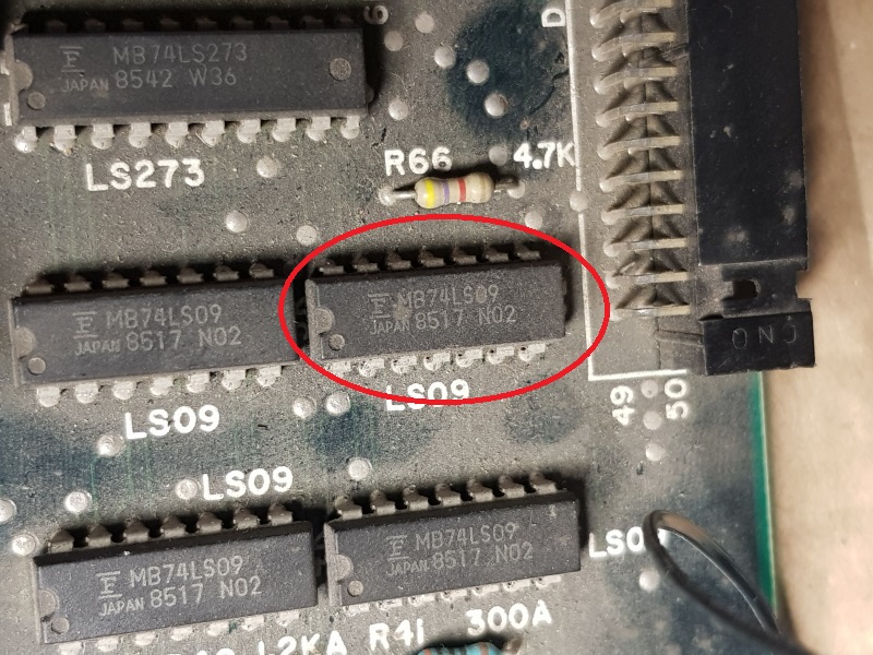
I didn’t have any of these spare so I removed the offending chip, which failed an out of circuit test, and moved on to the sound fault.
The sound is stuck in this constant loop. I started probing the Z80 in the sound section and all the pins appeared to be doing what they should.
I moved on to the EPROM and while all the usual pins seemed to be doing their thing, the VCC pin wasn’t what it should have been.
Checking the pin of the socket showed +5v
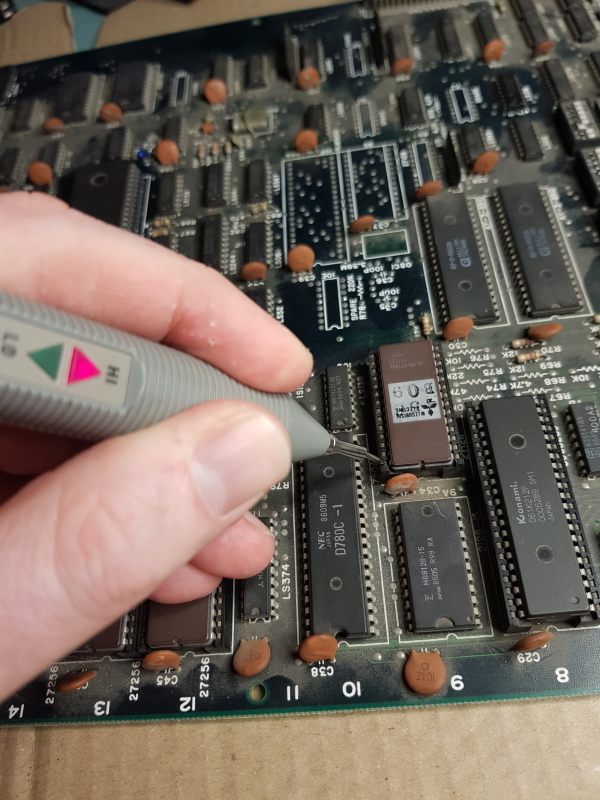
but checking the pin of the actual EPROM in the socket showed I had logic low on there.
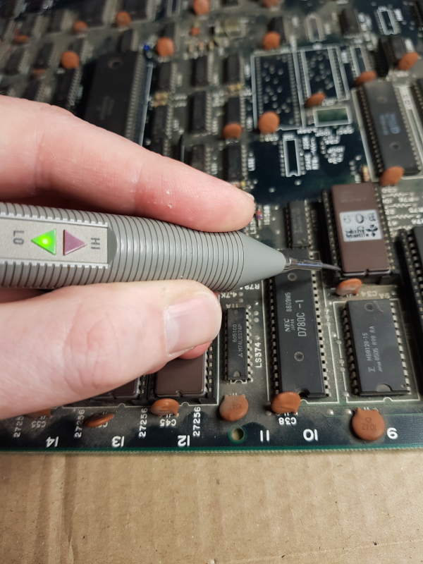
Wedging the logic probe tip between the socket and EPROM brought the sound back so I replaced the socket and the sound is fixed.
The 74LS09 replacement came the day after that and replaced it to fix this up
3 Responses to “Nemesis repair log #2”
Sorry, the comment form is closed at this time.
Evil Konami and Fujitsu defeated again!Well done!
Cheers 🙂
I have been following this blog for years and think very highly of the hard work you do. It has always surprised me how bad Fujitsu chips are, so much so that I steer clear of any tech with the Fujitsu name on it even now, lol