Apr 142015
 

Had this board for a while now but hadn’t looked at it.
IMAG1239

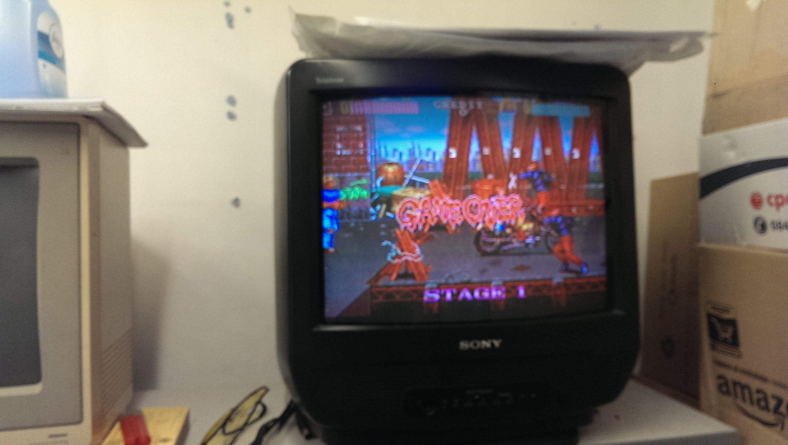
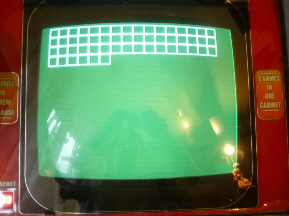
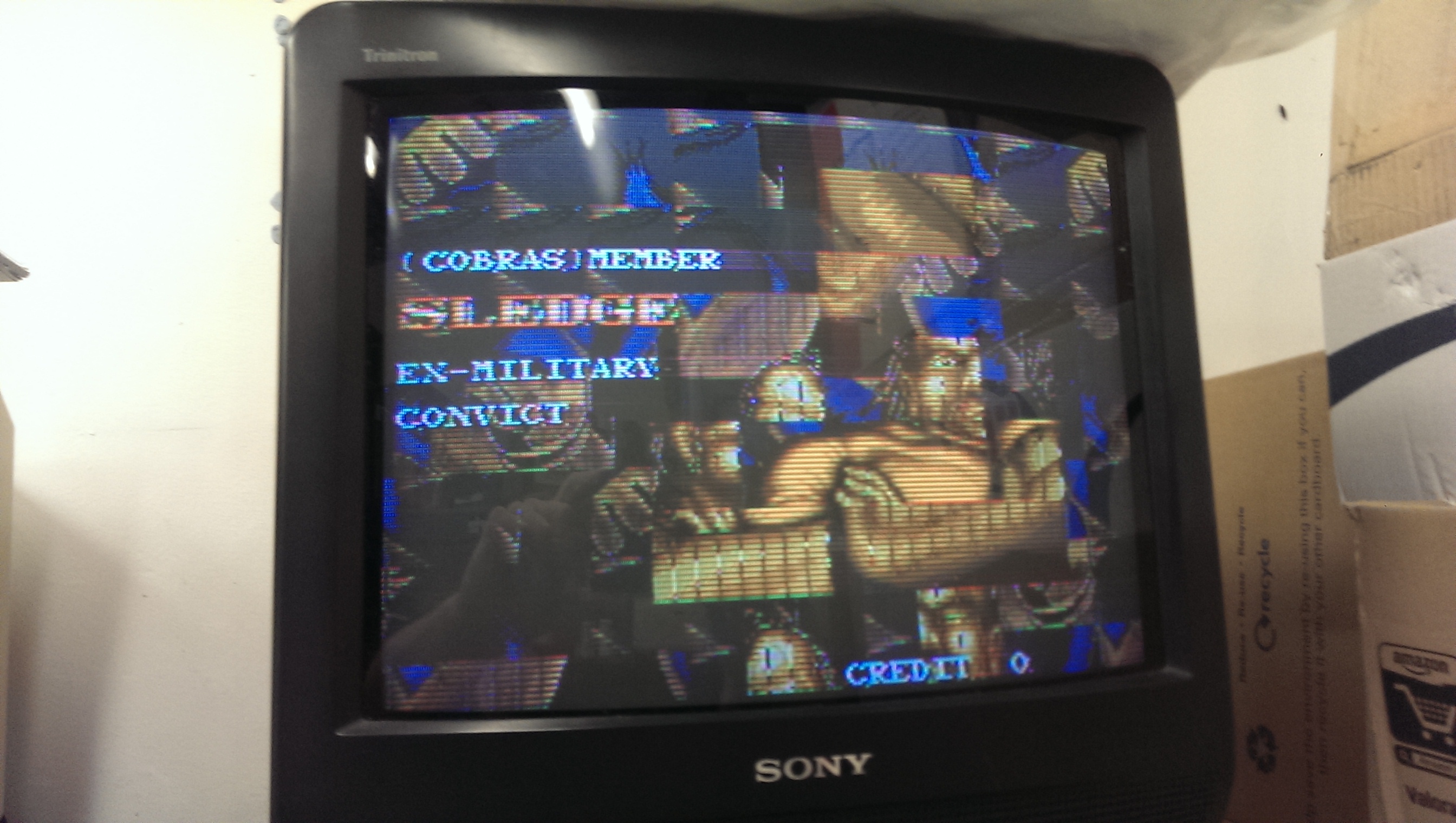
On booting the board up I got completely messed up graphics.
IMAG1238

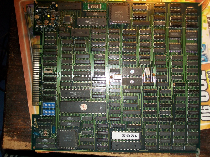
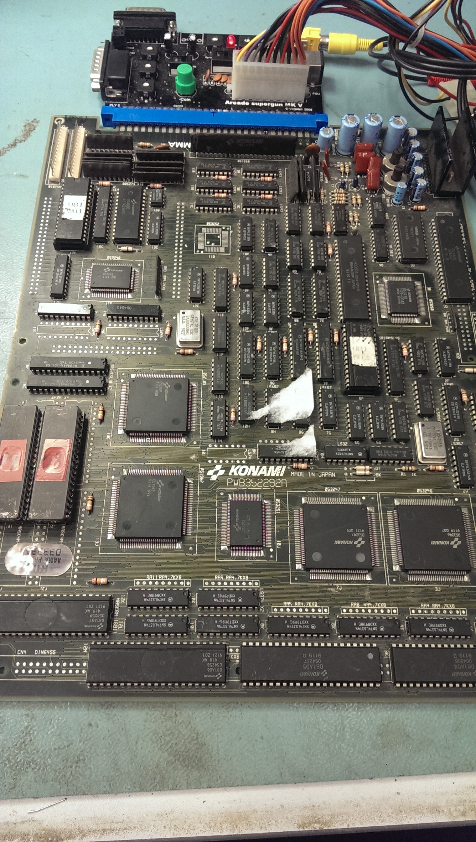
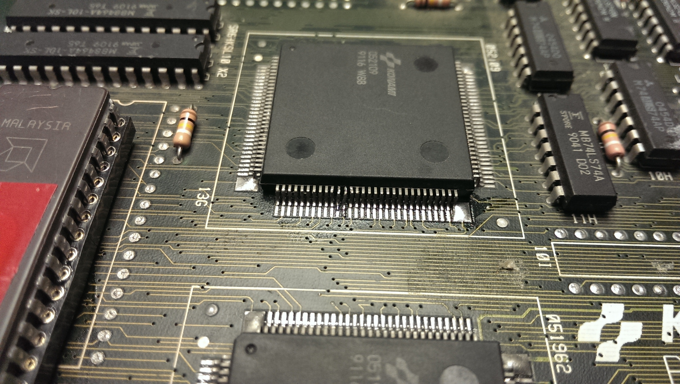
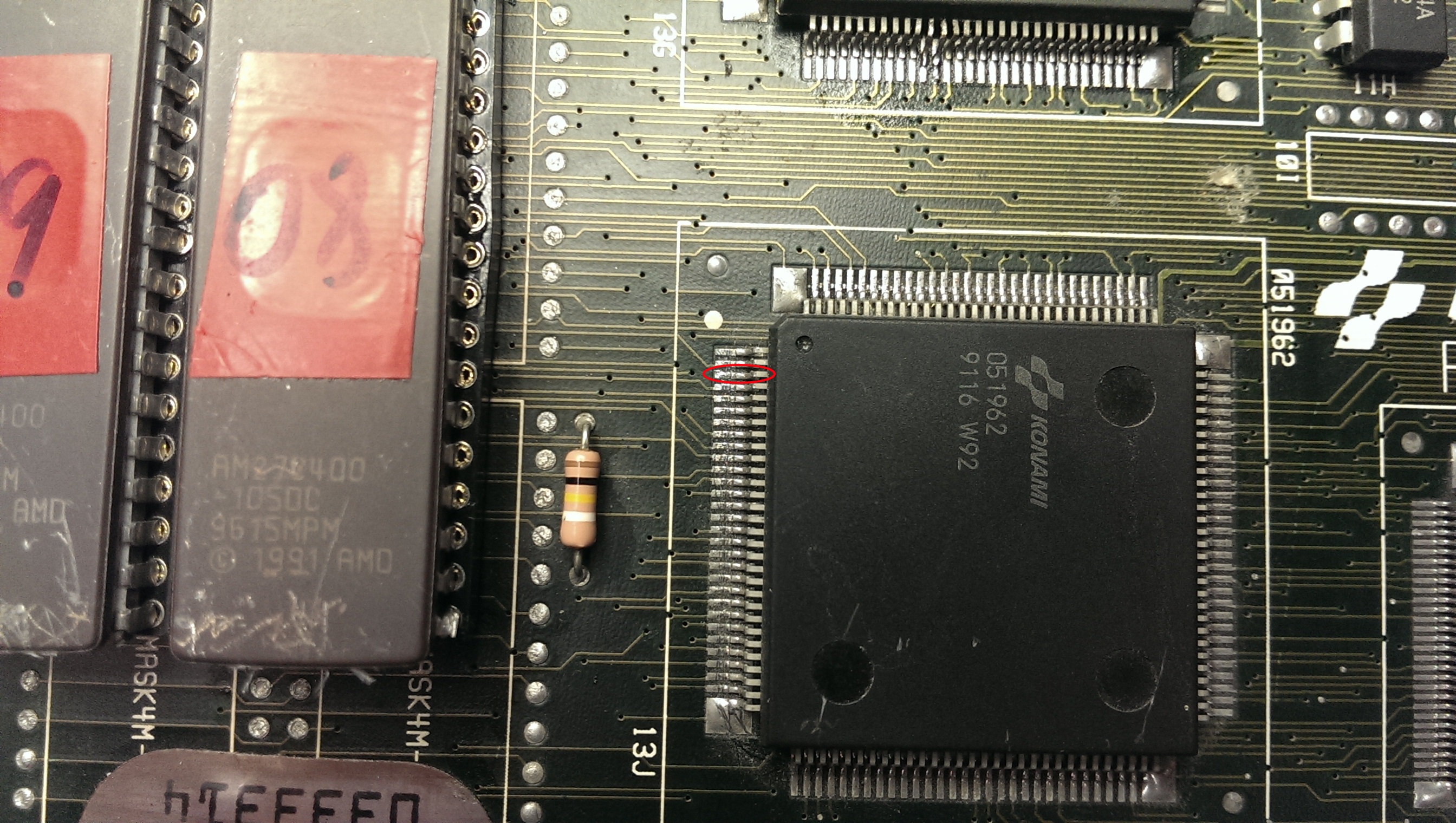
On my pre power up visual inspection I somehow missed the damage and solder blob on the 052109 tilemap generator.
IMAG1240

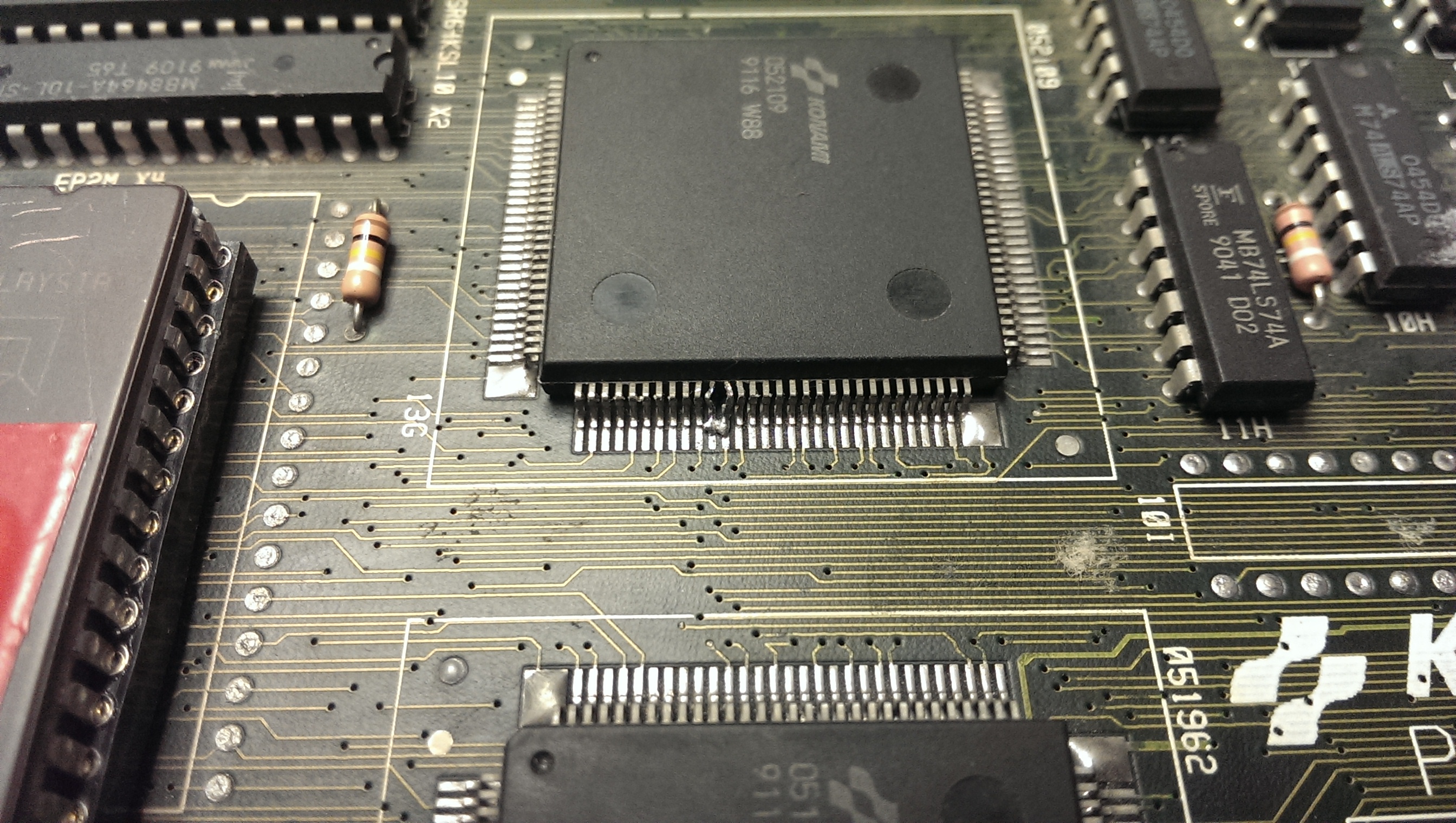
I removed the solder using solder braid and straightened the legs up best I could with some fine tweezers. It took a while as I didn’t want to snap the legs off but I ended up with something I was happy with.
IMAG1255

Fixing that gave me the graphics back but there were jailbars present.
IMAG1242

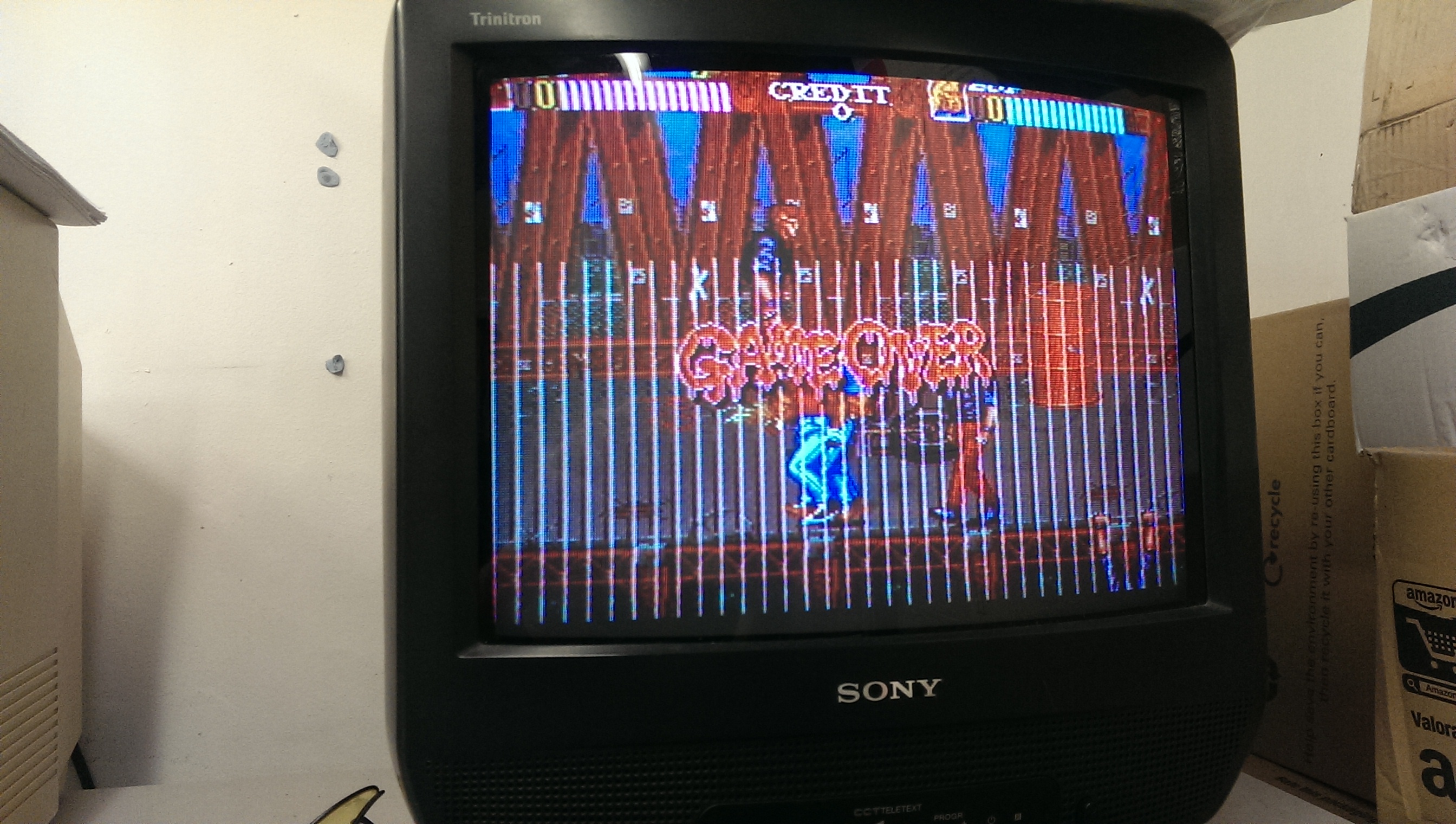
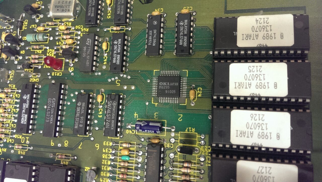
Jailbars are usually a sign of a failed ROM and as the two MASKROM’s have previously been replaced for a pair of 27C400 EPROM’s I thought it was best I check these out first.
Both turned out to be fine so the next step was to check the address and data line to see if they were active.
Again I could find no problems here.

I then found the test menu which runs a self test on these ROM’s. The ROM at location 16I gave a different checksum each time I ran the test. A changing checksum can be a sign of a floating data pin. I already knew the data pins were active and that the ROM’s were good so I set to work with the multimeter checking continuity between the EPROM and the 051962 tilemap generator which these data line go to.
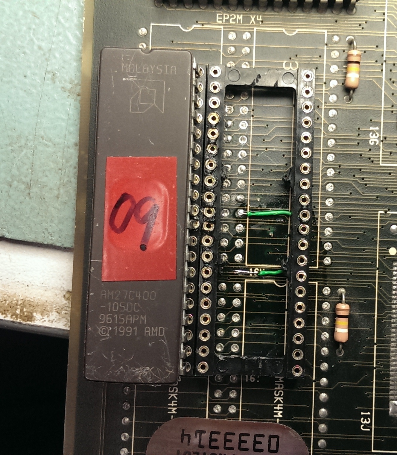
Eventually I found data pin 8 did not make it to the 051962.
IMAG1243

I was able to patch this underneath the EPROM so it would be hidden (and protected).
IMAG1244

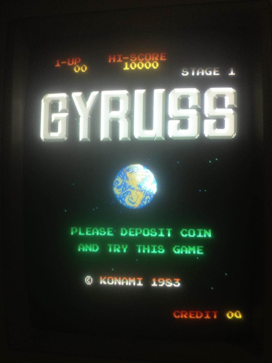
On powering up all the jailbars were gone and the board is fixed.
IMAG1253

Commodore 1084S-P1 repair log (part 1)

 Monitor Repair Log, Repair Logs  Comments Off on Commodore 1084S-P1 repair log (part 1)
Apr 052015
 

This was a quick fix .

Whilst testing the stereo sound of one of my CPS2 games I noticed the monitor display went blank all of a sudden. I thought there was a problem with the RGB connector but this was not to be the case.

I wasn’t getting a signal through the RGB connector or through composite on the back. Power led was on and neck glow was present so that was a good sign.

I opened up the monitor and discharged the tube using a flat-head screwdriver, a heavy gauge wire with two alligator clips on each end is also required.

Warning: Please don’t attempt to discharge a CRT unless you know what you’re doing!

See the following video from John’s Arcade for info on safely discharging CRT monitors.

Once discharged first thing I checked were the switches on the back of the monitor which gives the 1084 its various operating modes. Switches which handle those were fine & were set correctly. I recently re-flowed the solder to the connectors on the back which are notorious for creating intermittent problems.

I then began an inspection inside of the chassis, I was looking for bad capacitors in particular. I immediately spotted 1 really bad looking electrolytic that has seen better days.

1084simage

I had a spare Panasonic/Matsushita 50v 4.7mf capacitor in my parts bin which I happily replaced the bad one with. This seems to have done the trick and my display is back again.

A few other caps are budging slightly at their tops but I don’t have the right values yet.

In the near future I am going to recap the entire chassis since it shouldn’t be too long before another one fails completely.


Lei Shen Zhuan Thunder Deity Biography (Chinese hack of Battle Garegga) repair log

 PCB Repair Logs, Repair Logs  Comments Off on Lei Shen Zhuan Thunder Deity Biography (Chinese hack of Battle Garegga) repair log
Mar 292015
 

First of all, my apologies for the kilometric title but this seems be the correct one according to MAME which has emulated this game after my dumps 🙂

A friend of mine sent me this Battle Garegga bootleg PCB for a repair :

rsz_battle_garegg_bootleg

saying it had bad sound.Infact it was scratchy and noisy:

Besides, sometimes it muted completely.Regarding this last issue, I traced it to a bad YM2151 FM (actually a rebadged version marked ‘PD2001’) sound synthesis chip, once replaced it I got no more mutings.As for noisy sound, connecting the analog output (PIN12) of the YM3012 DAC (a ‘KA3002’ rebadged chip also here) to an external amplifier revealed that sound came out distorted.

Replaced it fixed the sound completely

 Posted by at 11:10 pm

Stun Runner repair log

 PCB Repair Logs, Repair Logs  Comments Off on Stun Runner repair log
Mar 292015
 

Had Muddymusic’s Stun Runner PCB for a long long time awaiting repair.
I put off looking at it because of how test bench unfriendly it would be to setup.
I did have most of the original loom to use but the audio section also used 13v AC and a test bench typically doesn’t have that.

I ordered a small 240v – 12v transformer and eventually set to work in hooking this thing up.
After half a day of messing around I had what I thought was a Stun Runner test rig.
While I had all the connections going to the right places and things like that I soon realised that the speakers I were using in now way suitable to check the sound and also my test bench monitors seem to be getting really picky about what they display properly.
In the end I settled for a black and white picture but I wasn’t too worried as the fault I was looking for was audio related.

The fault was that in game the music didn’t play and the engine tone played at a constant tone.
With my almost useless setup I could hear exactly this. I did a quick heat check with my finger on the audio PCB to check if any of the chips were getting hot and to my surprise all the sounds and music came back when I prodded the M6295.
IMG-20150310-WA0005

I powered down and reflowed the chip and all was working again.
I soak tested it as best I could and called it a day.

Muddymusic has now got it back and has confirmed the sounds and music are now good.

Mar 242015
 

About a month ago I purposely purchased a non working Gyruss off eBay to repair myself for fun. This repair would later inspire me to develop the Gyruss test rom which is currently being developed right now.

Symptoms: Game watch-dogging. Only gets as far as the grid test pattern, sometimes partial then resets perpetually.

$_57

First thing was to check the voltages from various +5v rails on the bottom board. Voltages were measuring quite low, around 4.7v. I have read that low voltages would also contribute to  this behavior. Adjusting the +5v didn’t help.

Next step was to verify all the game ROMs via romident which checked out good. Cleaned pins on all socketed chips, no change. Probed Z80 main CPU, confirmed barking reset line.

Removed both Z80s which tested good in known working Galaga board. Installed IC sockets and re-installed Z80s.
Began process of purging all Fujitsu branded ttls before troubleshooting with some Fujitsu branded ttls still remaining.

Four 74ls163s that are used for memory addressing the 2149 srams tested bad on my Micromaster LV48 device programmer ( but they turn out to be good after fixing the game and re-substituting the 163s back in. The ls161s that I had lying around seemed to work fine as well ). Caius said that these are difficult to test out of circuit so the result of the tests performed by my not so trusty Micromaster LV48 almost lead me in the wrong direction with this repair.

With the 161s installed the symptoms were exactly the same which prompted me to look at other areas as I didn’t believe these would cause the fault, these chips seem to be associated with the video display.

I checked some non Fujitsu ttl logic around the main CPU & 2kx8bit SRAMs. 13E & 14E ( LS245 ) tested good. 17C,5J,3J ( 2kx8bit SRAM ) tested good, 2J tested BAD ( 2kx8bit SRAM ).

@ 0x00000H expected 01, read 00

I was pretty sure that I found the culprit. Bad work ram would definitely cause this kind of issue.

Socketed 17C,5J,3J & 2J ( SRAMs). Replaced 2J with a Sanyo LC3517.

Retested with good results.

photo(1)