Real Break – Billiard Accademy repair log

 PCB Repair Logs, Repair Logs  Comments Off on Real Break – Billiard Accademy repair log
Aug 302015
 

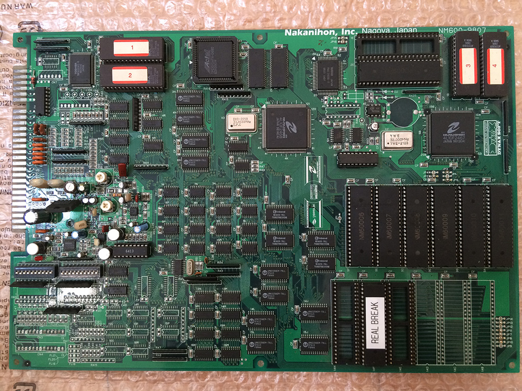
Bought this board as fully working for 30 euros but turned out it had a problem on the audio.

Foto 30-08-15 09 26 59

All the music and sound effects were totally disturbed and garbled.

The TA8201AK amplifier was becoming so hot that you could smell it burning.

The pcb has a lot of smd capacitors that are reknown to be unreliable but I noticed that two of them were already changed with normal ones.

I was sure that it was the amplifier shorted internally because in some occasions my 2A fuse was blown so I bought from ebay a cheap one for 4 euros.

Foto 30-08-15 09 27 34

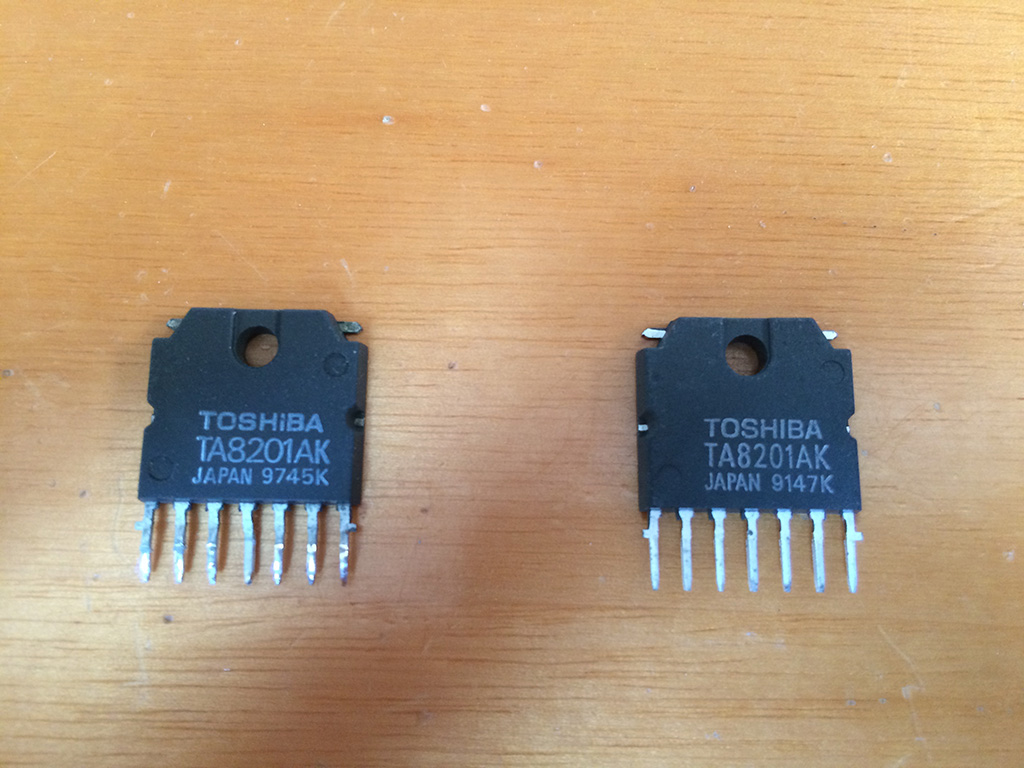
On the left side the original one dated 1997, on the right the one bought on ebay, dated 1991 😉

After soldering the new one, the problem remained.

This time I decided to go for more professional approach and downloaded the datasheet and checked all the caps and resistances according to the sample circuit.

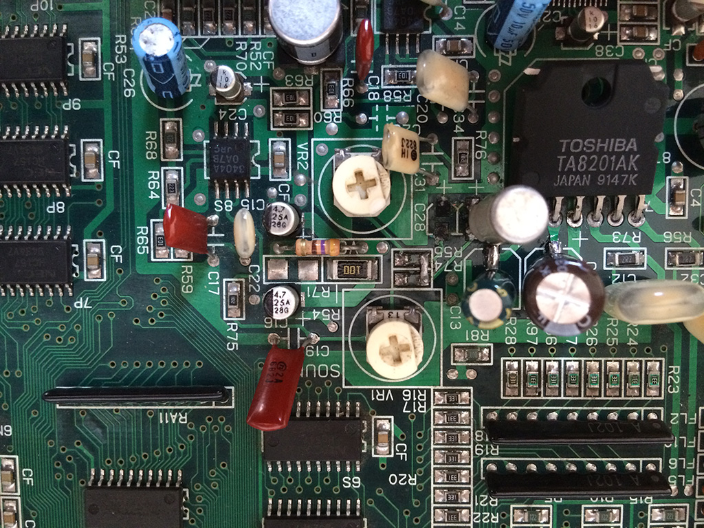
To make a long story short, the two tiny caps (C28 and C29, one for the sound sfx and one for the music) connected to the input of the amp were somewhat faulty and leaking under the body.

Foto 30-08-15 10 46 45

After desoldering both of them , I noticed they were1nF each and not compliant to the suggested one of the datasheet which should be 4,7uF.

I decided to install only one cap of 4,7uF and shorted the resistances R55 and R74 to mix the sounds before the cap.

This solved completely the issues and got very clean sound with the amplifier running with a reasonable temperature.


Aug 302015
 

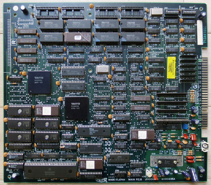
I bought a dead Rastan PCB for a fair price on a forum.

rastan1

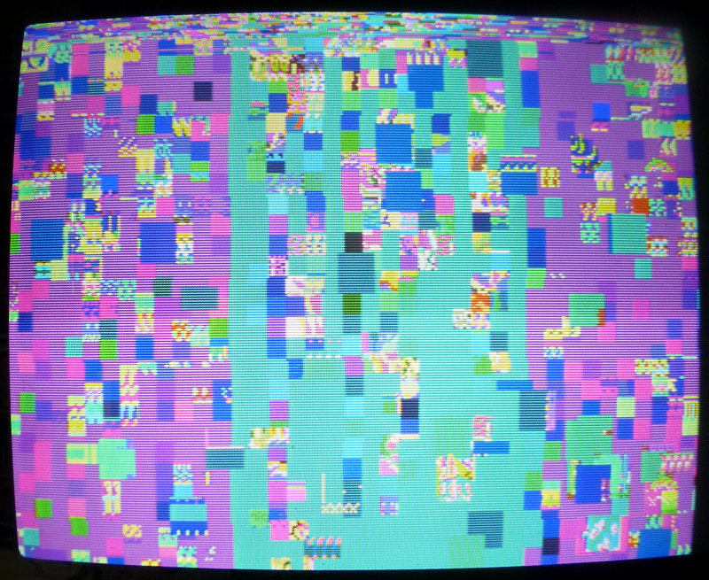
All I got was a screen with garbled graphics on boot:

rastan2

Luckily, schematics are available online for this board. Anyway, I spent hours with my scope trying to find why there was no activity at all in the CPU area. I desoldered the two RAMs and the 68000 (all were tested OK as well as the ROMs).

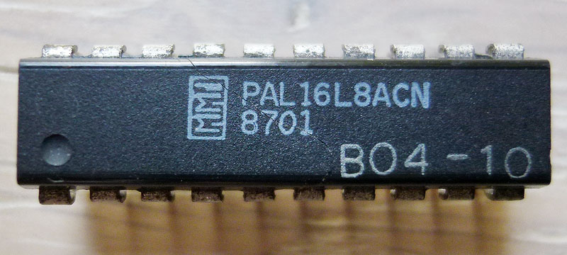
Next, I desoldered the 2 PALs that are involved in the address decoding (labeled B04-09 @ IC11 and B04-10 @ IC12) in order to check them and finally discovered that B04-10 was slightly cracked (it is the one at the bottom-left corner of the board, you could figure it was heavily bended there) and, with no surprise, it couldn’t be read on my programmer. See the crack in the middle of the chip, it was unnoticeable before removal:

rastan5

Fortunately, PALs for this game are available on JAMMArcade.net so I took a blank GAL and burned the equivalent file but then got a black screen… Ok, that was my fault as the file was an untested dump from a PAL16L8 and needed to be converted to GAL16V8 in order to work properly. I did the conversion with PALTOGAL.EXE, reburned it then the game booted !

Great… But my enthusiasm quickly stopped as I noticed some issues:

1) The game sometimes crashed then rebooted, it happened 1/3 times when I started a game.

2) There was no sound (I could sometimes randomly hear a voice looping then fading away).

3) A few sprites were garbled.

It turned out that both issues 1) and 2) were related to a defective sound RAM chip @ IC50.

System11 reports the exact same problem on one of his Rastan repair logs (corrupted sound with main CPU crashing randomly due to a defective sound RAM).

This was not easy to troubleshoot because that RAM @ IC50 had seemingly “normal” pulsing signals on every pins and piggybacking didn’t worked at first. After reading that repair log from System11, I tried again piggybacking and that time it worked ! (well, it partially worked and not all the time)
So I’ve replaced the chip and got it working fine with sound and no freezes !

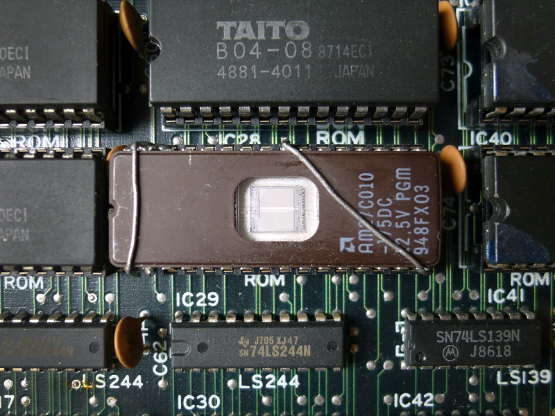
Only the issue 3) was remaining. The fault was most probably due to one of the gfx mask ROMs @ IC28 (1Mbit into a 28pins chip) that was replaced by an hacked 27C010 1Mbit 32pins EPROM. I could see things changing when touching a couple of pins on the EPROM. Here is a picture of it:

rastan3

I could replace this bad looking hacked EPROM with a blank TC531000, LH531000 or a HN62331 mask ROM as they seems to have the exact same specs and size than the original mask ROM but it seems nearly impossible to find these chips nowadays.

After comparing the pinouts between 1Mbit 32pins EPROM and 1Mbit 28pins MASK ROM I found what was missing on that hack: pin #2 (A16) of the EPROM was not going anywhere and it should be connected to pin #22 on the socket. I soldered a thin wire on the EPROM and plugged it underneath the chip on the socket.

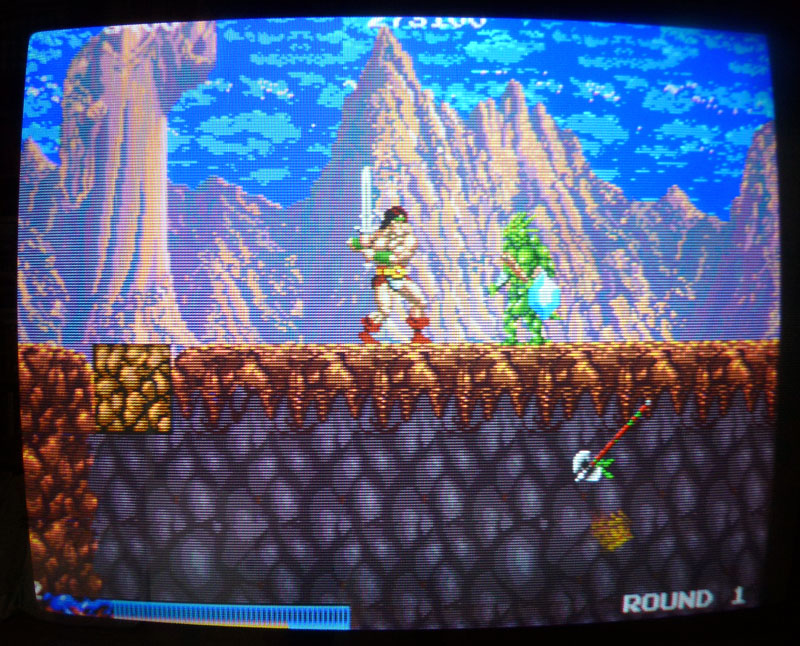
Plugged back the chip and the gfx were then fully fixed ! (as an example, this axe on the bottom-right corner was garbled before):

rastan4

Alright, BUT… After playing the game for a few minutes, I noticed when dying that Rastan’s voice was suddenly cut and looped 3 times along with his jumping voice. If I had to replace what I heard with words that would make: DYING/cut/JUMPING/DYING/cut/JUMPING/DYING/cut.
Well, that sounded weird so a verification in the emulator confirmed that was not normal.

The test mode features a sound test so I compared all the voices between my board and the game in MAME and there was 3 voices replaced by this looping sound of Rastan’s dying/jumping.

Alright, had to look back at the schematics…

This was (most probably) related to the voice generating part which is pretty small fortunately as it involves only a few TTLs as well as the Z80, one EPROM and one M5205 (ADPCM sound generator).
Sound ROMs were tested OK and every address and data lines looked fine.

Checking the related TTLs with the scope, I noticed there was no pulsing signals on every of the 5 outputs of the 74LS193 @ IC60 while its inputs were pulsing. This chip is a counter and it is partially doing the link between the sound data bus and the voice address bus. There is another 74LS193 @ IC77 doing the same work for other address/data lines and outputs were pulsing when I pushed the button to generate one of Rastan’s voice in the sound test.

Piggybacking the chip at IC60 made the voices working fine with no weird loop. Also the other voices in the sound test were back. Replaced the chip and finally have now a perfectly working Rastan. (well, played it a few hours and it runs perfectly !)

Thanks to Porchy and Caius for their help on the PAL and hacked EPROM.

Aug 292015
 

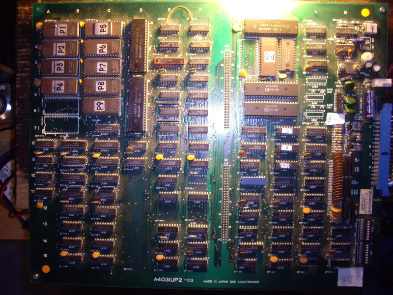
A friend asked me if I could take a look at his dead Super Contra PCB which was a 2 boards version (the same game exist in a single board version where all the small mask ROMs on the sub board are replaced by bigger mask ROMs on the main board).

scontra1

All I got was a black screen with no sound. Checking with a scope around the CPU area revealed there was almost no activity. The CPU is a Konami custom 052001, hard to troubleshoot as I couldn’t find its pinout online.

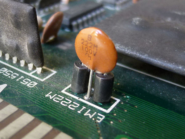
While checking for possible loose connections on some chips. I found that bending a bit this small chip near the JAMMA connector (an electromagnetic interference filter) was booting the game:

scontra2

It was a bit loose. I desoldered it and found one of its legs broken. This was hidden behind one of these two small black ferrites. I repaired the leg and resoldered it.

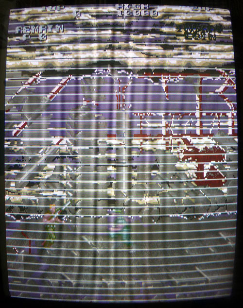
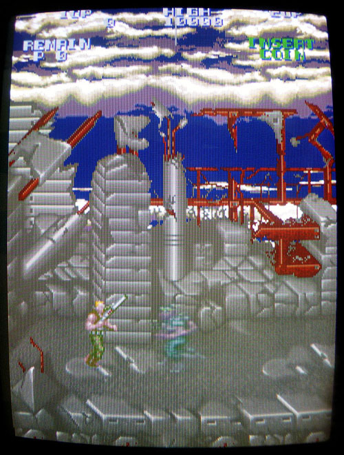
Well, the game was now booting but graphics were a bit messy:

scontra4

ROMs containing graphics and voices are located on the sub board.

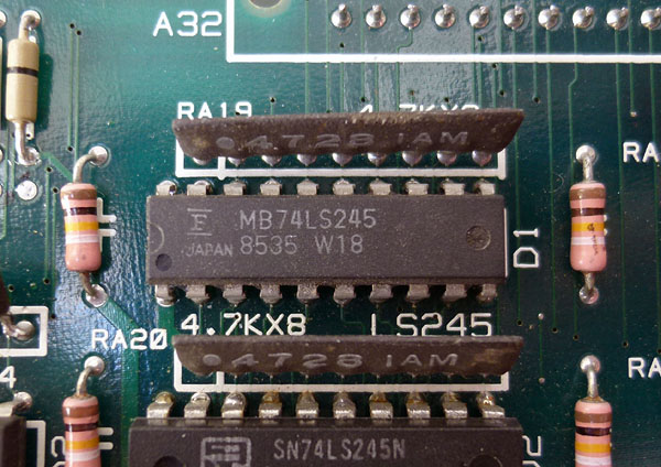
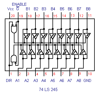
I started checking this part as it has a pretty simple layout (basically mask ROMs with buffers) and noticed 3 mask ROMs with corrupted signals on their data lines. These 3 ROMs were all connected on the same bus to pins 2 to 9 (A bus) of a 74LS245 buffer @ location D1:

scontra3

74LS245

There are several other 74LS245 chips connected to other mask ROMs on the board and they all seemed to have “normal” activity signals. The B bus of the suspected chip (pins 11 to 18) seemed inactive and was connected to a custom chip on the main board.

I first tried piggybacking that 74LS245 @ D1 but nothing happened. The lines were still looking the same with garbage signal on bus A side, which could be caused by the possibly faulty chip itself. I desoldered it and it was tested bad on my IC programmer. I put a new one in place and the problem was resolved:

scontra5

Here is what every signal on the A bus (pins 2 to 9) of the 74LS245 chip looked like with the faulty chip (left) then with a new chip in place (right). You can clearly see how bad the signal looked like on the left:

HAL21 repair log

 PCB Repair Logs, Repair Logs  Comments Off on HAL21 repair log
Aug 272015
 

Got this HAL21 PCB from my frend Josef for a repair.The game is  a vertical shoot ’em up produced by SNK in 1985, a mix between Xevious, Terra Cresta and Alcon.

Board was in good shape given its age:

HAL 21_PCB

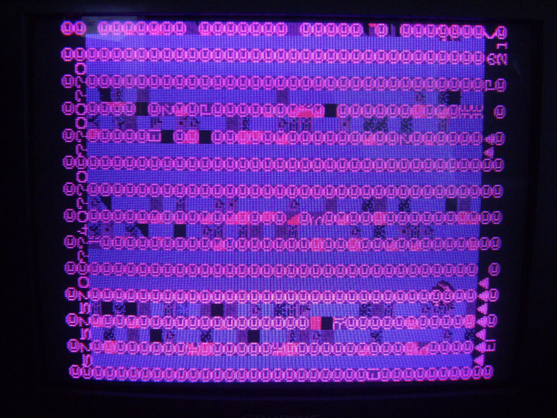
but fautly since it didn’t boot at all, stuck on a static garbage screen:

no_boot_missing_red

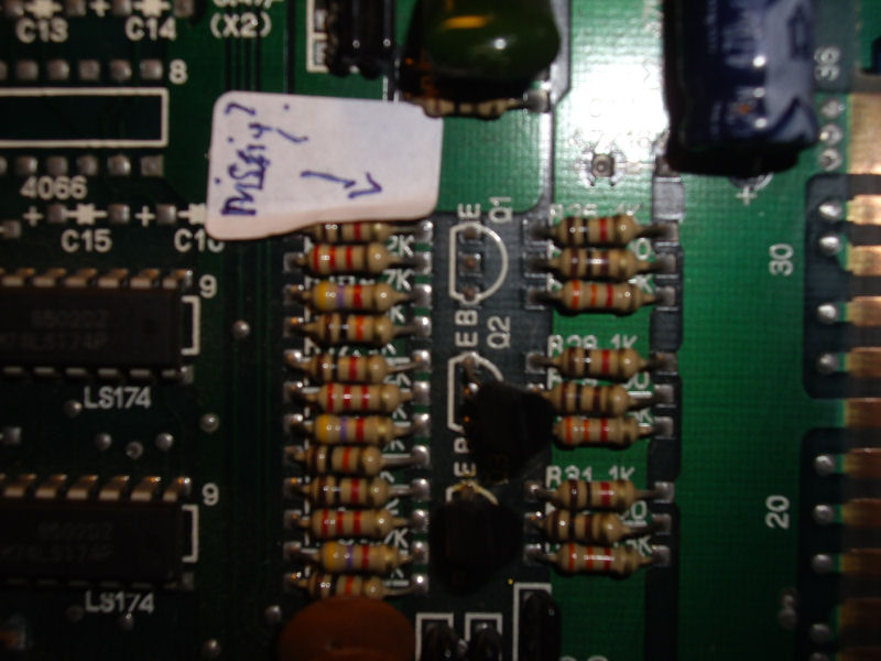
First thing I noticed (besides the fact that it didn’t boot) was the wrong colors, specifically the red one was missing. My friend Josef gave me an hint pointing me to a missing transistor 2SC1815 @Q1 near the edge connector:

2SC1815_missing@Q1

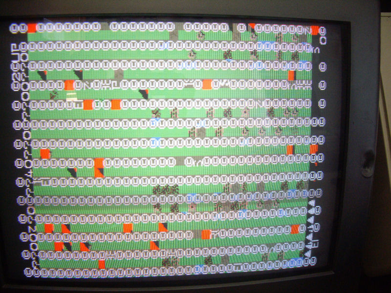
Actually this transistor was for driving the RED ouput (the other two are for BLUE and GREEN) so replacing it restored correct colors:

no_boot_correct colors

So, I started my real troubleshooting .Hardware is made of two Z80 CPUs ( a main and sub one) plus a third one for the sound.I decided to hook up my Fluke 9010A in order to perform some test on main CPU.MAME source reports this memory  map for the RAMs:

AM_RANGE(0xe000, 0xe7ff) AM_RAM AM_SHARE(“spriteram”) // + work ram
AM_RANGE(0xe800, 0xf7ff) AM_RAM_WRITE(marvins_bg_videoram_w) AM_SHARE(“bg_videoram”)
AM_RANGE(0xf800, 0xffff) AM_RAM_WRITE(snk_tx_videoram_w) AM_SHARE(“tx_videoram”) // + work RAM

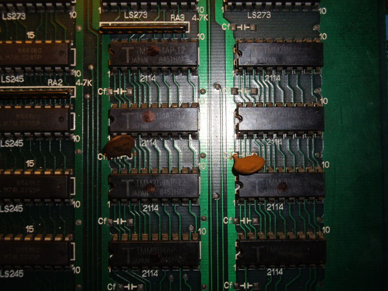
When I performed a long RAM test on the first and third address spaces, I get an R/W error from Fluke 9010A.With the help of its probe, I could located the involved chips, eight 2114 of video board:

2114_RAMs

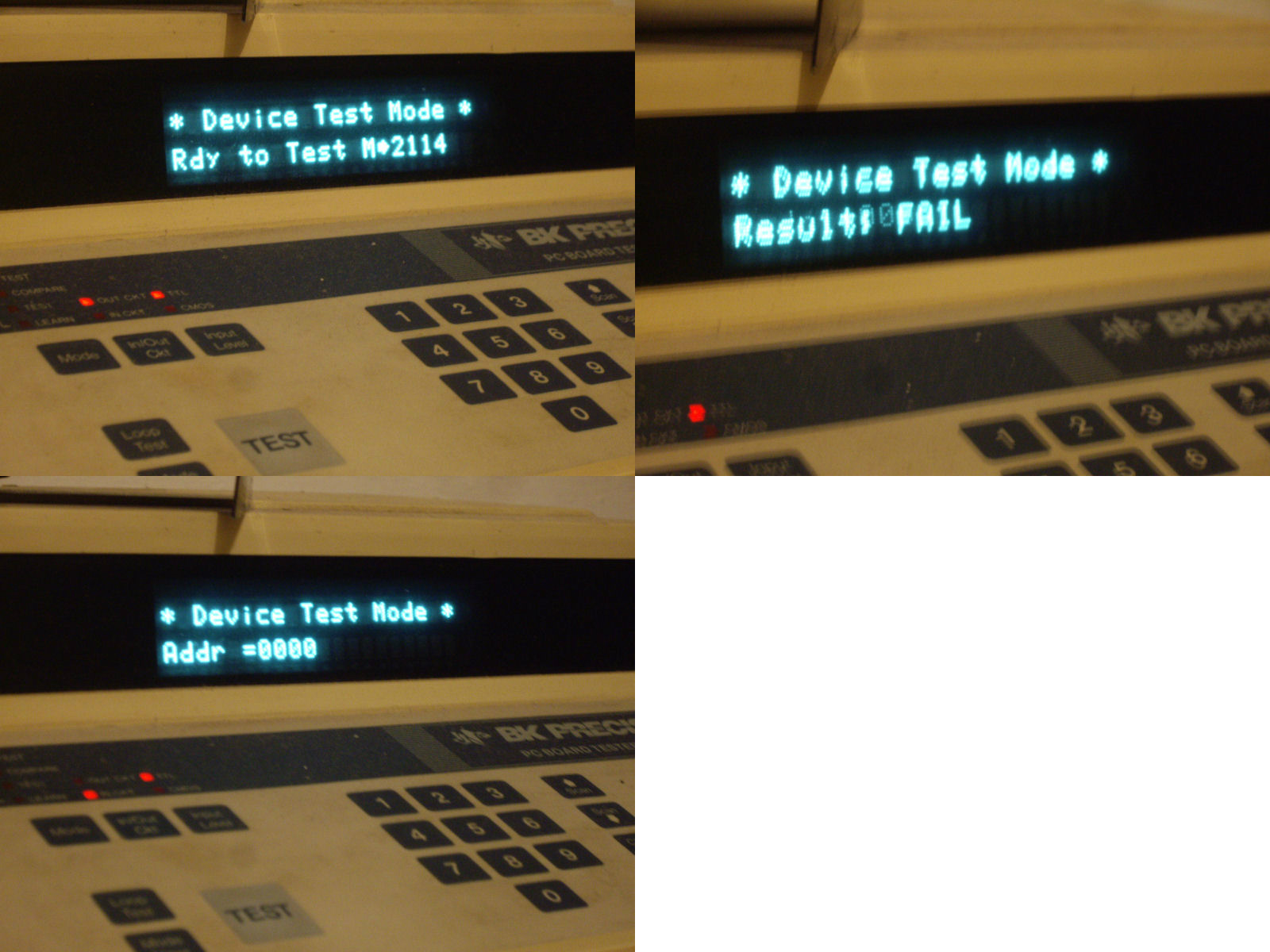
I probed them with my BK Precision 560A in-circuit tester which reported bad devices for the four ones on the right :

2114_in-circuit

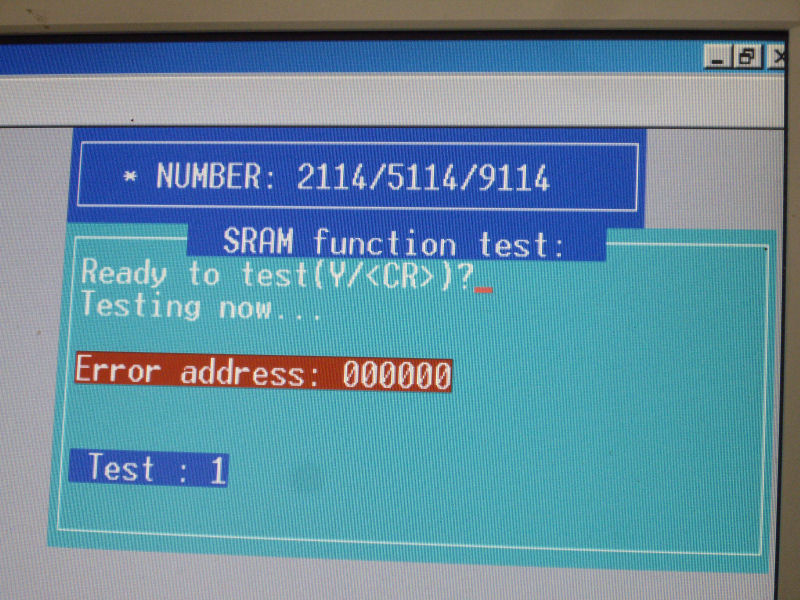
I took this result with reservations, most likely not all four chips were bad but one certainly and  this affected the other ones (due the fact they share same address bus) misleading the tester.Not being able to accurately identify the faulty chips I desoldered all the four and I found two bad ones @6L and 7L:

2114_failed_out_of_circuit

With two good 2114 RAMs fitted, the board properly booted with no further issues.Mission accomplished.

fixed

 Posted by at 9:07 pm
Aug 252015
 

Got this Sunset Riders PCB always in a trade with my friend Ifog:

Sunset Riders_PCBJPG

Board was really in mint condition but, as my friend warned me, it was faulty.

Actually when I first powered it up it played perfectly but after some minutes it showed an issue where some parts of graphics had wrong colors (pinkish, I’d say) :

color_issue

Since I have repaired other similar Konami boards with same issue, I already knew where start to look at.Palette RAMs are two 2018 devices @13D and 14D:

pallette_RAMs

I probed them with my oscilloscope but didn’t notice anything abnormal (though they were hot at touch), also piggybacking them didn’t change anything.So, I went more ahead in the palette circuitry following the path of the data bits of these RAMs.Just before the generation of the three RGB colors there are some open-collector buffers (74LS07):

palette_circuitry

Probing the one @8C with my scope, I found discrepancies between input pin 3 and output pin 4:

7407@8C_waveform

Once desoldered, the IC failed on pin 4 indeed:

7407@8C

Comparing on a tracer the bad output with a good one, you can see how the internal junction was altered (good one on the left of the below picture):

7407@8C_comparing_tracer

Fitted a good IC fixed the colors.

Success!

 Posted by at 11:31 pm