Aug 292015
 

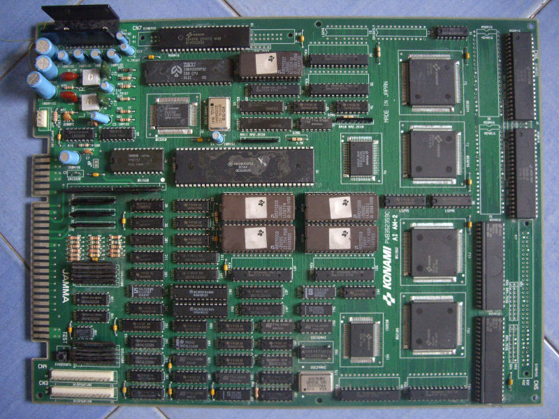
A friend asked me if I could take a look at his dead Super Contra PCB which was a 2 boards version (the same game exist in a single board version where all the small mask ROMs on the sub board are replaced by bigger mask ROMs on the main board).
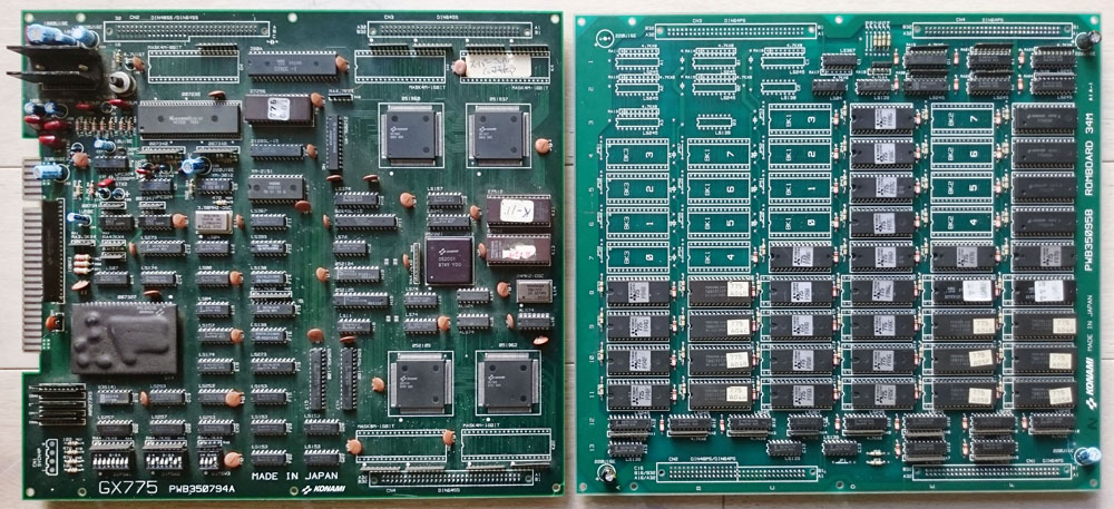
scontra1

All I got was a black screen with no sound. Checking with a scope around the CPU area revealed there was almost no activity. The CPU is a Konami custom 052001, hard to troubleshoot as I couldn’t find its pinout online.

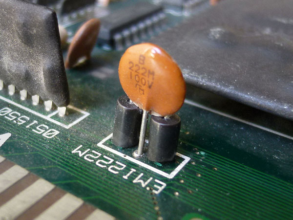
While checking for possible loose connections on some chips. I found that bending a bit this small chip near the JAMMA connector (an electromagnetic interference filter) was booting the game:
scontra2

It was a bit loose. I desoldered it and found one of its legs broken. This was hidden behind one of these two small black ferrites. I repaired the leg and resoldered it.

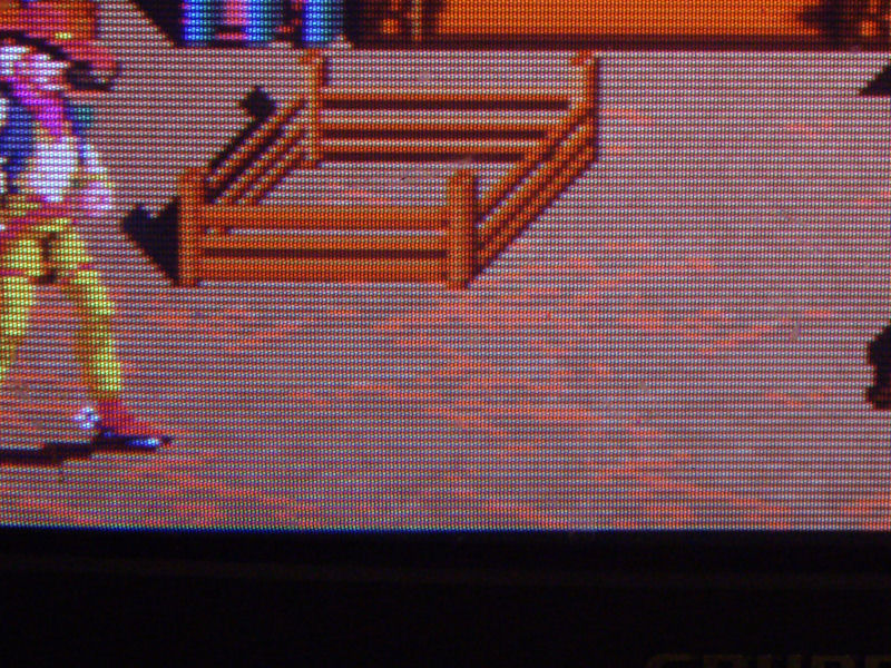
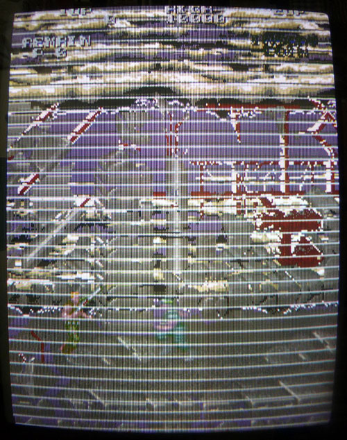
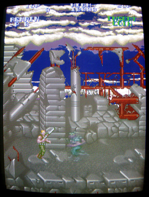
Well, the game was now booting but graphics were a bit messy:
scontra4

ROMs containing graphics and voices are located on the sub board.

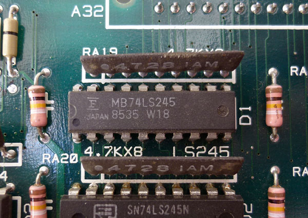
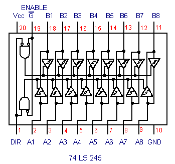
I started checking this part as it has a pretty simple layout (basically mask ROMs with buffers) and noticed 3 mask ROMs with corrupted signals on their data lines. These 3 ROMs were all connected on the same bus to pins 2 to 9 (A bus) of a 74LS245 buffer @ location D1:
scontra3

74LS245

There are several other 74LS245 chips connected to other mask ROMs on the board and they all seemed to have “normal” activity signals. The B bus of the suspected chip (pins 11 to 18) seemed inactive and was connected to a custom chip on the main board.

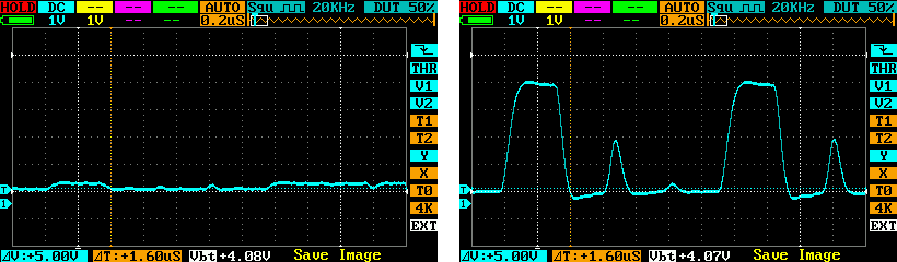
I first tried piggybacking that 74LS245 @ D1 but nothing happened. The lines were still looking the same with garbage signal on bus A side, which could be caused by the possibly faulty chip itself. I desoldered it and it was tested bad on my IC programmer. I put a new one in place and the problem was resolved:
scontra5

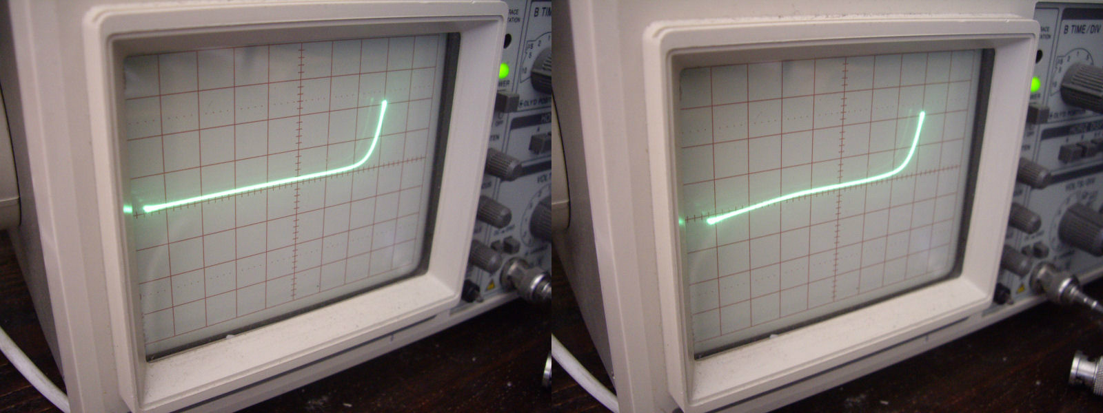
Here is what every signal on the A bus (pins 2 to 9) of the 74LS245 chip looked like with the faulty chip (left) then with a new chip in place (right). You can clearly see how bad the signal looked like on the left:
HAL21 repair log

 PCB Repair Logs, Repair Logs  Comments Off on HAL21 repair log
Aug 272015
 

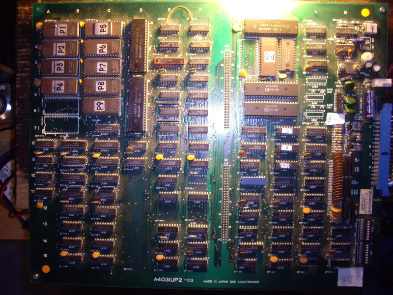
Got this HAL21 PCB from my frend Josef for a repair.The game is  a vertical shoot ’em up produced by SNK in 1985, a mix between Xevious, Terra Cresta and Alcon.

Board was in good shape given its age:

HAL 21_PCB

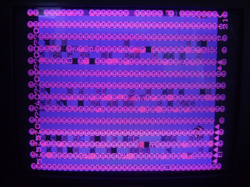
but fautly since it didn’t boot at all, stuck on a static garbage screen:

no_boot_missing_red

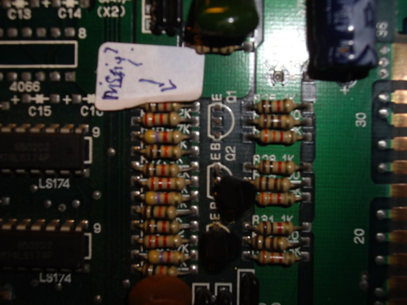
First thing I noticed (besides the fact that it didn’t boot) was the wrong colors, specifically the red one was missing. My friend Josef gave me an hint pointing me to a missing transistor 2SC1815 @Q1 near the edge connector:

2SC1815_missing@Q1

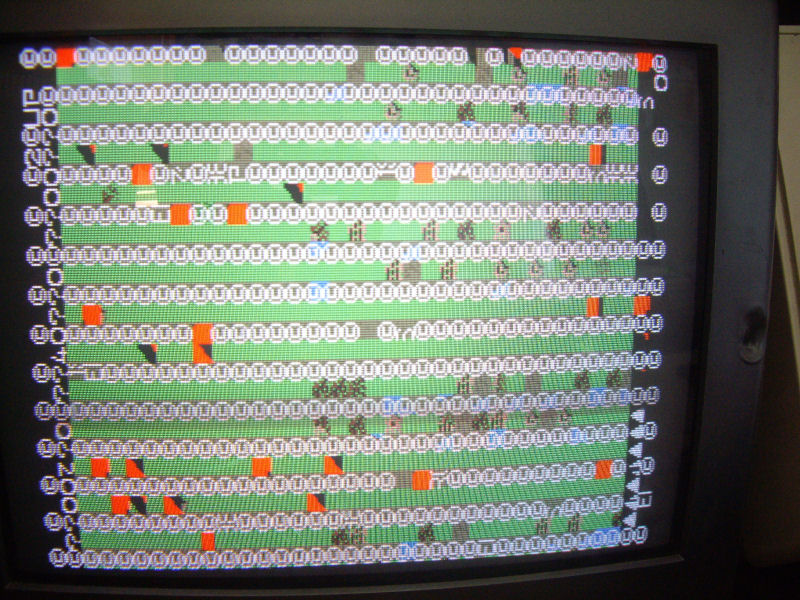
Actually this transistor was for driving the RED ouput (the other two are for BLUE and GREEN) so replacing it restored correct colors:

no_boot_correct colors

So, I started my real troubleshooting .Hardware is made of two Z80 CPUs ( a main and sub one) plus a third one for the sound.I decided to hook up my Fluke 9010A in order to perform some test on main CPU.MAME source reports this memory  map for the RAMs:

AM_RANGE(0xe000, 0xe7ff) AM_RAM AM_SHARE(“spriteram”) // + work ram
AM_RANGE(0xe800, 0xf7ff) AM_RAM_WRITE(marvins_bg_videoram_w) AM_SHARE(“bg_videoram”)
AM_RANGE(0xf800, 0xffff) AM_RAM_WRITE(snk_tx_videoram_w) AM_SHARE(“tx_videoram”) // + work RAM

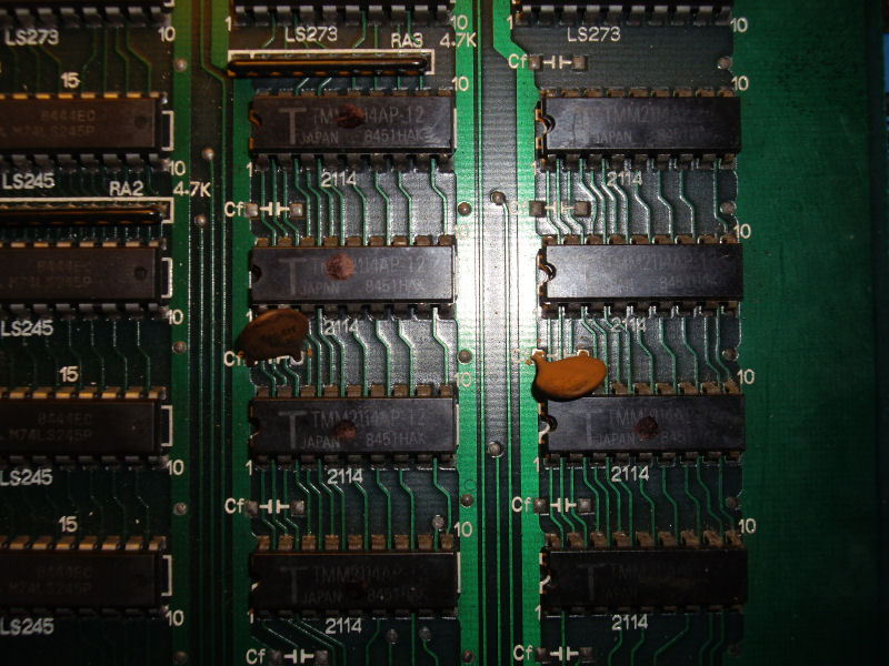
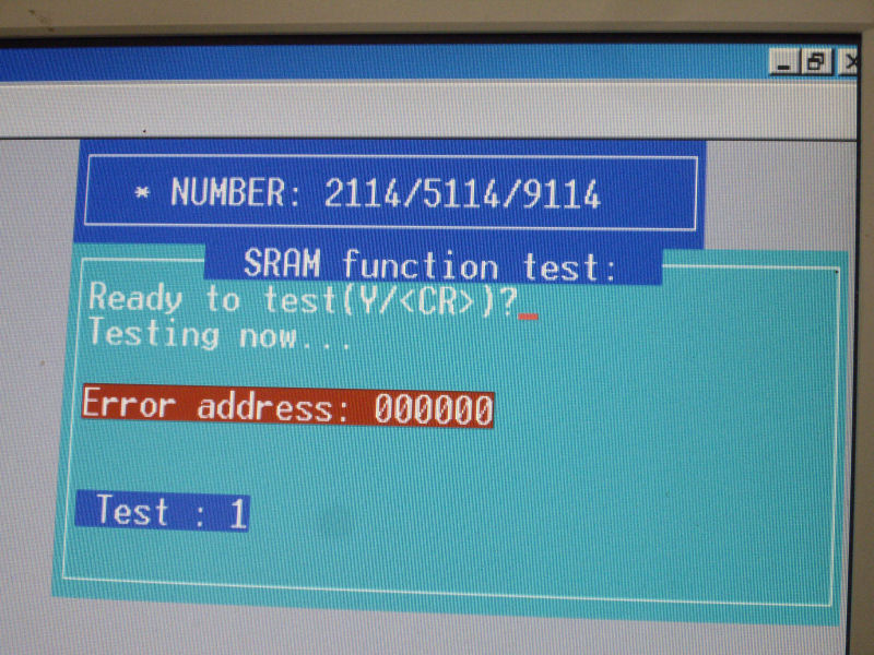
When I performed a long RAM test on the first and third address spaces, I get an R/W error from Fluke 9010A.With the help of its probe, I could located the involved chips, eight 2114 of video board:

2114_RAMs

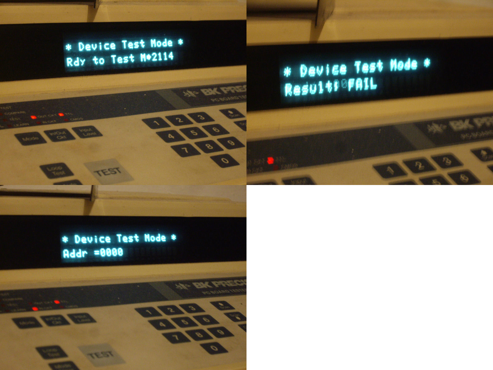
I probed them with my BK Precision 560A in-circuit tester which reported bad devices for the four ones on the right :

2114_in-circuit

I took this result with reservations, most likely not all four chips were bad but one certainly and  this affected the other ones (due the fact they share same address bus) misleading the tester.Not being able to accurately identify the faulty chips I desoldered all the four and I found two bad ones @6L and 7L:

2114_failed_out_of_circuit

With two good 2114 RAMs fitted, the board properly booted with no further issues.Mission accomplished.

fixed

 Posted by at 9:07 pm
Aug 252015
 

Got this Sunset Riders PCB always in a trade with my friend Ifog:

Sunset Riders_PCBJPG

Board was really in mint condition but, as my friend warned me, it was faulty.

Actually when I first powered it up it played perfectly but after some minutes it showed an issue where some parts of graphics had wrong colors (pinkish, I’d say) :

color_issue

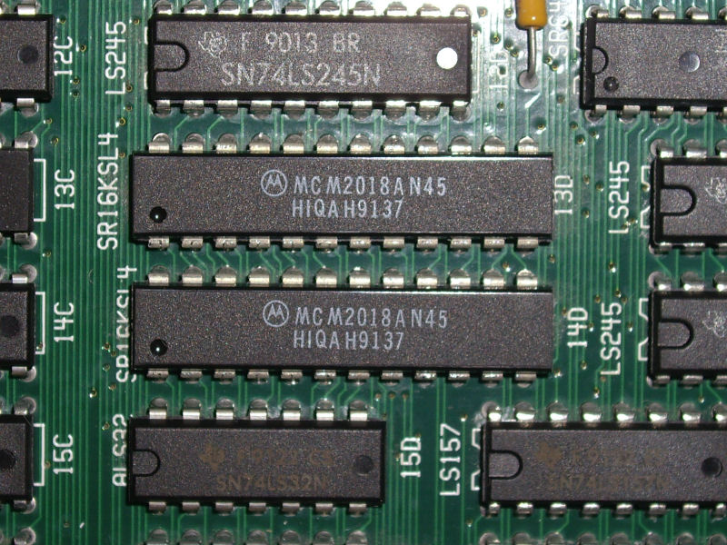
Since I have repaired other similar Konami boards with same issue, I already knew where start to look at.Palette RAMs are two 2018 devices @13D and 14D:

pallette_RAMs

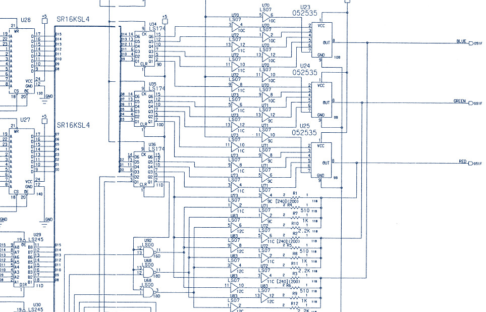
I probed them with my oscilloscope but didn’t notice anything abnormal (though they were hot at touch), also piggybacking them didn’t change anything.So, I went more ahead in the palette circuitry following the path of the data bits of these RAMs.Just before the generation of the three RGB colors there are some open-collector buffers (74LS07):

palette_circuitry

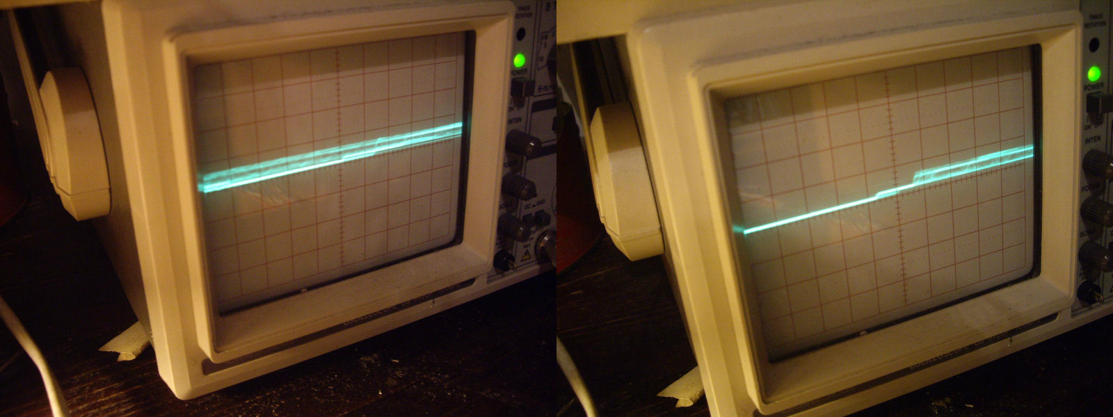
Probing the one @8C with my scope, I found discrepancies between input pin 3 and output pin 4:

7407@8C_waveform

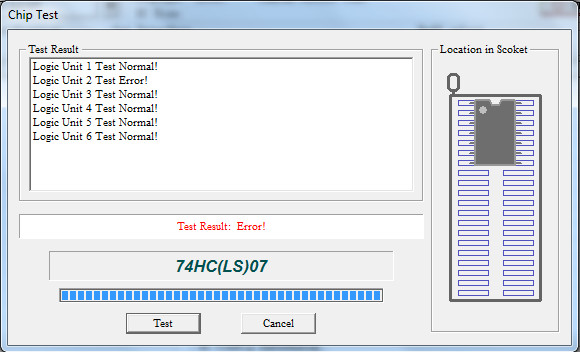
Once desoldered, the IC failed on pin 4 indeed:

7407@8C

Comparing on a tracer the bad output with a good one, you can see how the internal junction was altered (good one on the left of the below picture):

7407@8C_comparing_tracer

Fitted a good IC fixed the colors.

Success!

 Posted by at 11:31 pm

Fluke 90 repair log

 Equipment Repair Logs, Repair Logs  Comments Off on Fluke 90 repair log
Aug 232015
 

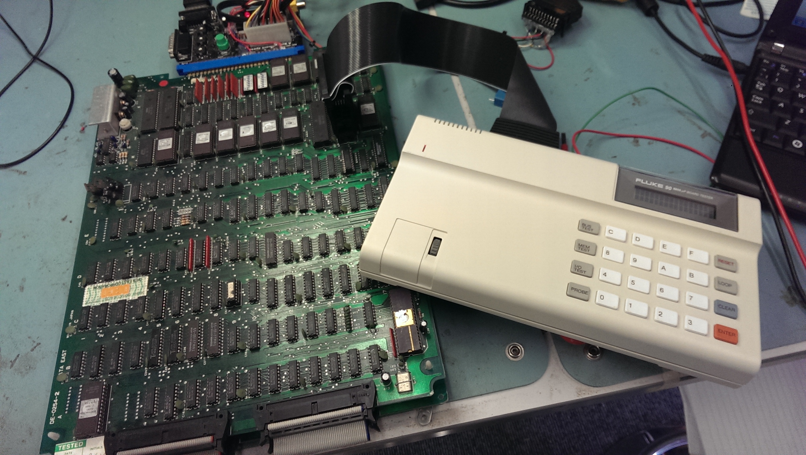
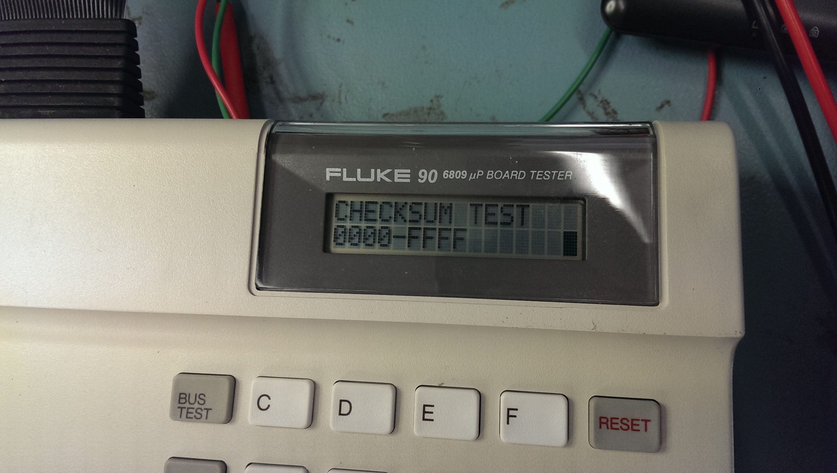
I’ve come to the conclusion that I will probably never own the 6809 pod for the Fluke 9010. Accepting this fact led me to find a Fluke 90 6809 tester.
These things are a far cry away from the capabilities that the Fluke 9010 offers but they still offer some decent functionality.

I got one of these from the US quite recently and it was, as far as I could tell, unused. It was still in its wrapping and is in pristine condition.
Ive got a couple of games that use 6809 CPU’s to hand so thought I would give it a try out.
IMAG1483

I first pulled Breywood out and clipped the test clip over the CPU but I got an “ERROR 4 UUT CPU BUS REQUEST FAIL”. This means that the /HALT signal cannot be driven.
Its at this point I found the “Getting Started” guide online.
This states that the /HALT line cannot be tied to VCC. Breywood does indeed have this pin tied directly to VCC (and not even via a resistor).
Thinking about it I probably caused this fault by not reading the manuals prior to using it.

Time to break this thing open.
IMAG1485

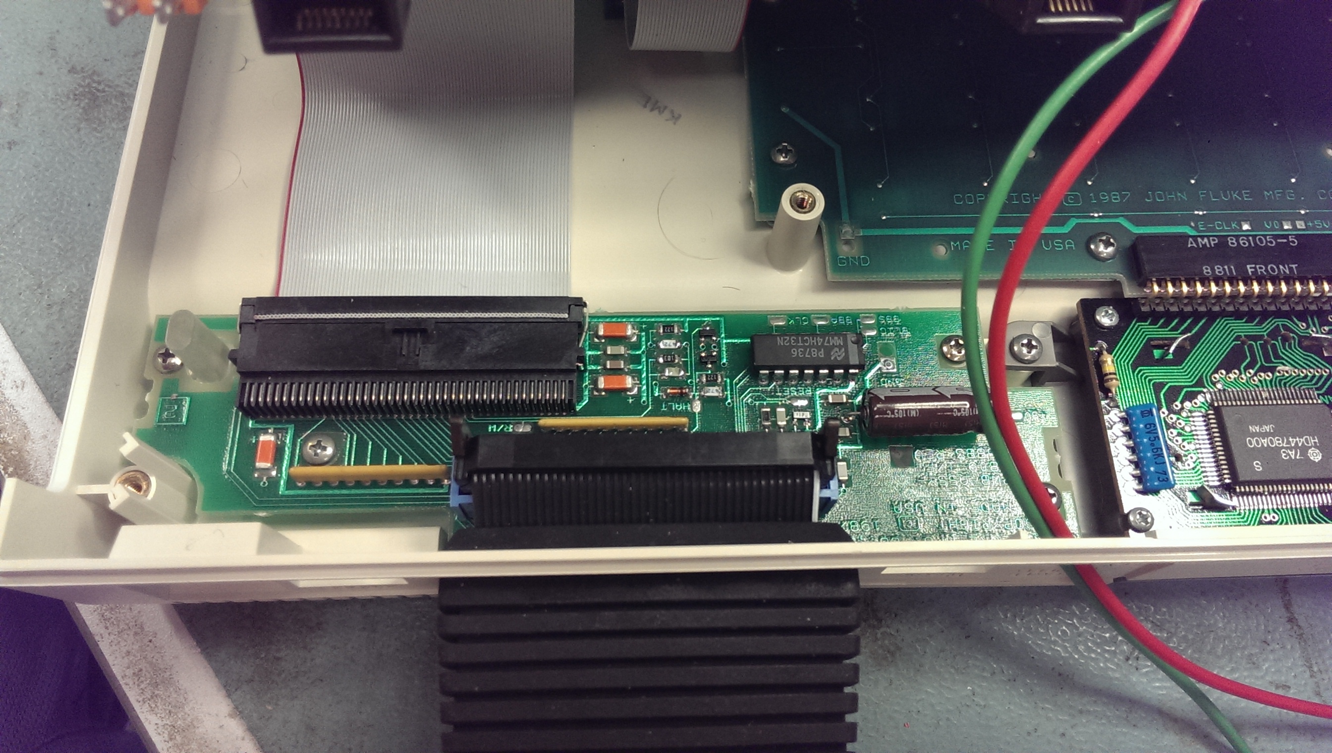
The Fluke 90 needs to be able to drive the /HALT pin and it also does a check on startup that it can do this. If it cannot drive the pin then it flags up the fail message.
As you can see in the above picture there are a few discreet components for this section. Doing some quick poking around with the logic probe revealed that the emitter on one of the NPN transistor (towards the top on the picture) was dead. I removed the transistor and checked it out of circuit, sure enough it was dead.
I replaced both of these transistors just in case and tested.
IMAG1482

Everything now seems to be working fine.
I’m really pleased with this unit. It has some nice features like being able to set breakpoints (if connected to a PC)

 Posted by at 4:39 pm

Knuckle Bash repair log #1

 PCB Repair Logs, Repair Logs  Comments Off on Knuckle Bash repair log #1
Aug 212015
 

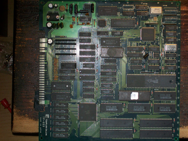
Got this faulty Knuckle Bash PCB in a trade with my friend Ifog:

Kuckle Bash_PCB

For the uninitiated, it’s a side-scrolling beat ’em up developed and published by Toaplan in Japan in the 1993.

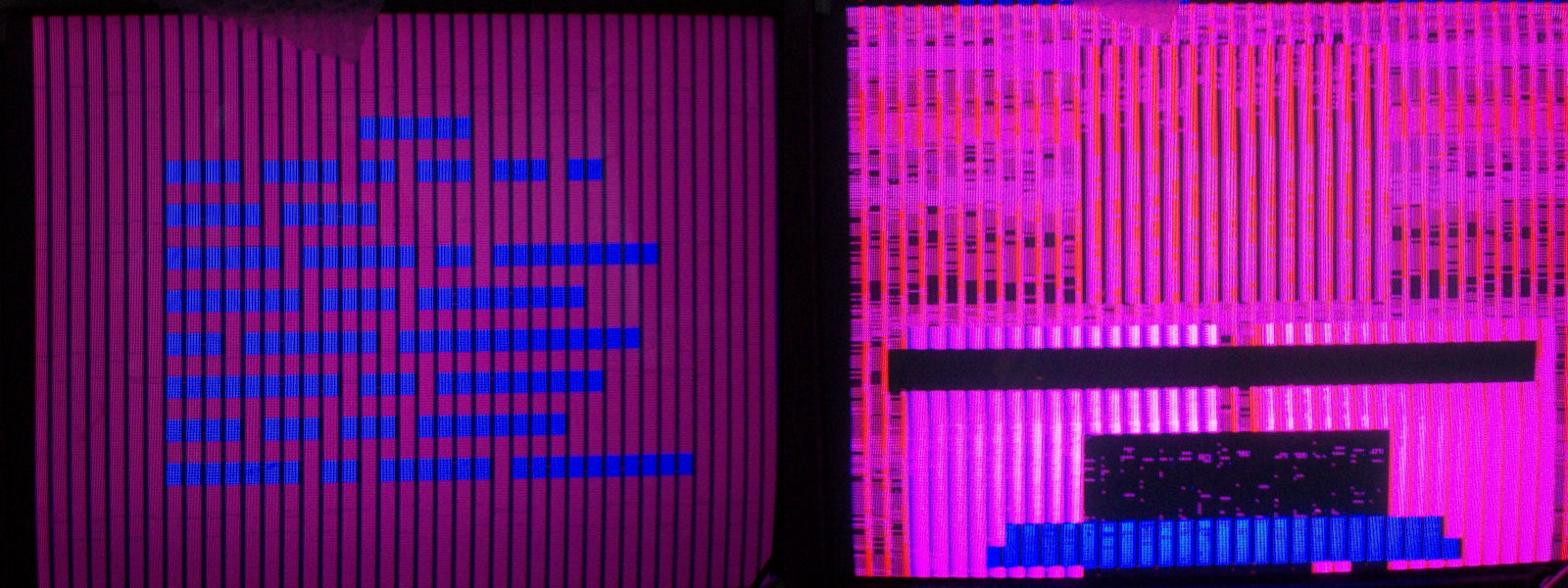
As expected, on the power up I was greeted by this scenario:

issue

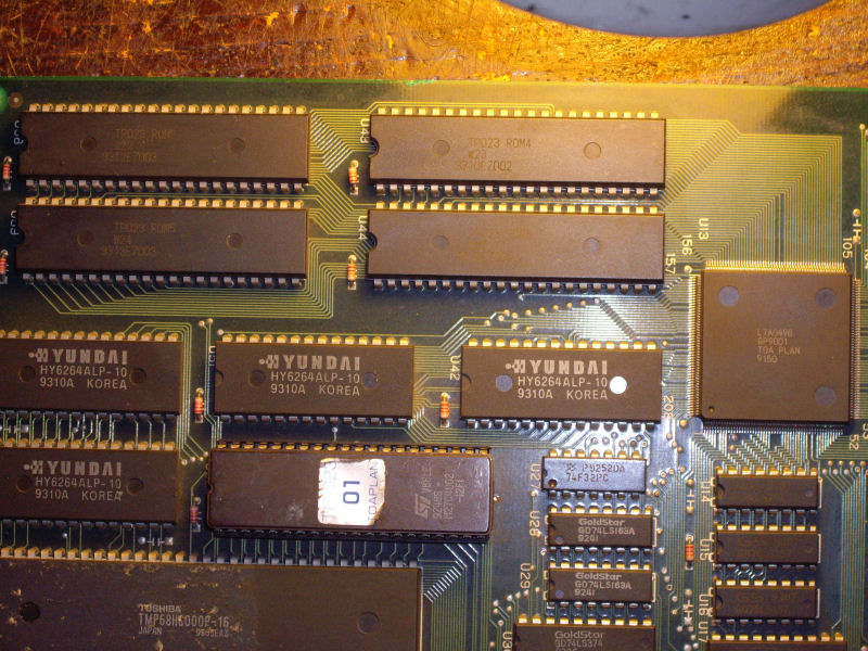
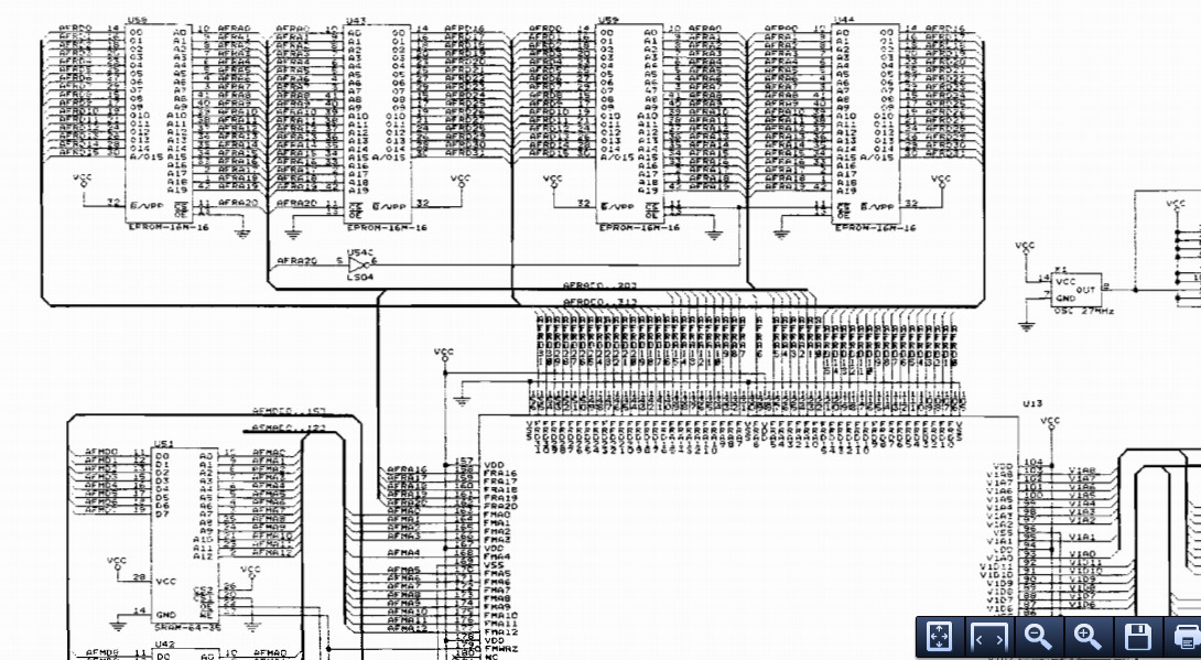
Game was playing almost blind, all graphics were totally wrong replaced by colored blocks.All the GFX DATA are stored in four 42 PIN 16Mbit MASK ROMs:

GFX_MASK_ROMs

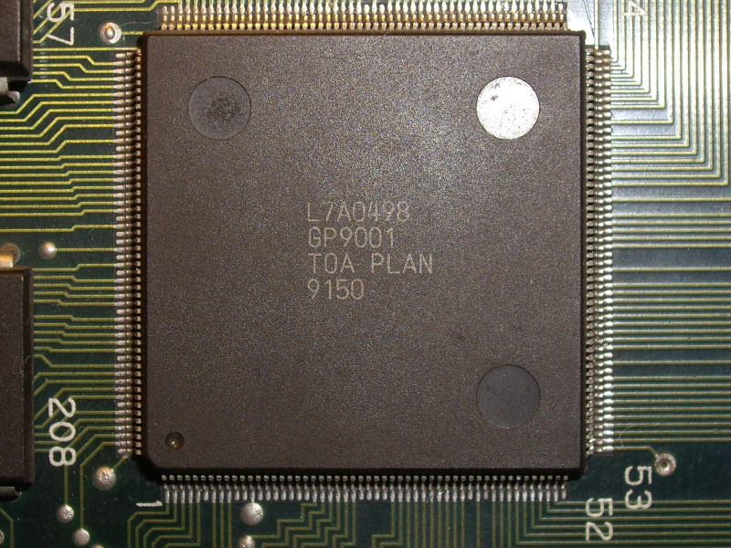
These devices are addressed by the near custom ASIC ‘GP9001’ @U13 which is the graphics processor unit of the system:

GFX_custom

Also schematics confirmed this:

GFX_MASK_ROMs_addressing

When I went to probe address lines of the MASK EPROMs, I found that most of them were silent.A closer inspection revealed the many pins were lifted.Pressing the custom chip with a clamp (a rude method perhaps but always effective) restored all the GFX :

fixed_with_clamp

So, I did a reflow of the custom chip passing the iron tip on its pins (with the clamp still in place) and this fix GFX stably.

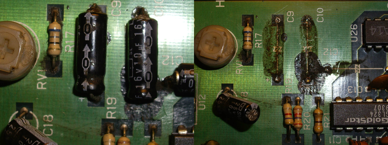
Last thing to do was replacing some leaking 10mF axial electrolytic capacitors in the audio section (luckily corrosion didn’t involve any traces ) :

leaking_capacitors

Another great game preserved to eternity (well, hopefully…)!

P.S.

This board turned to be an undumped Korean revision.I sent dumps to MAME developers.

 Posted by at 7:25 pm