Sunset Riders repair log #2

 PCB Repair Logs  Comments Off on Sunset Riders repair log #2
Sep 262015
 

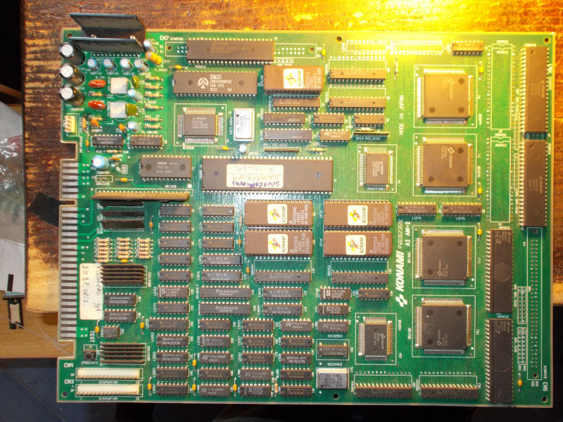
Got this Sunset Riders PCB for a repair:

Sunset Riders_PCB

Gameplay and graphics were OK but music was accelerated and distorted:

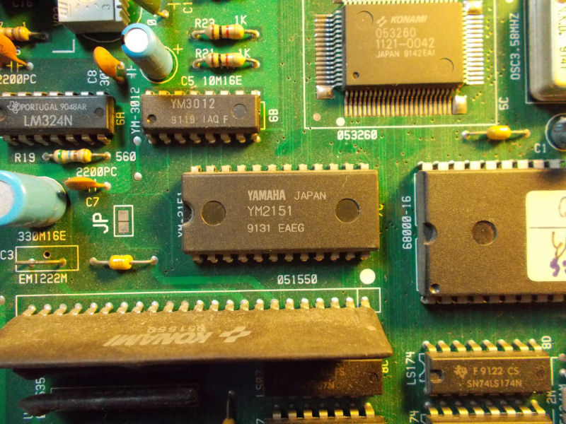
Music is generated by the YM2151 sound synthesis chip widely used in many arcade systems:

YM2151

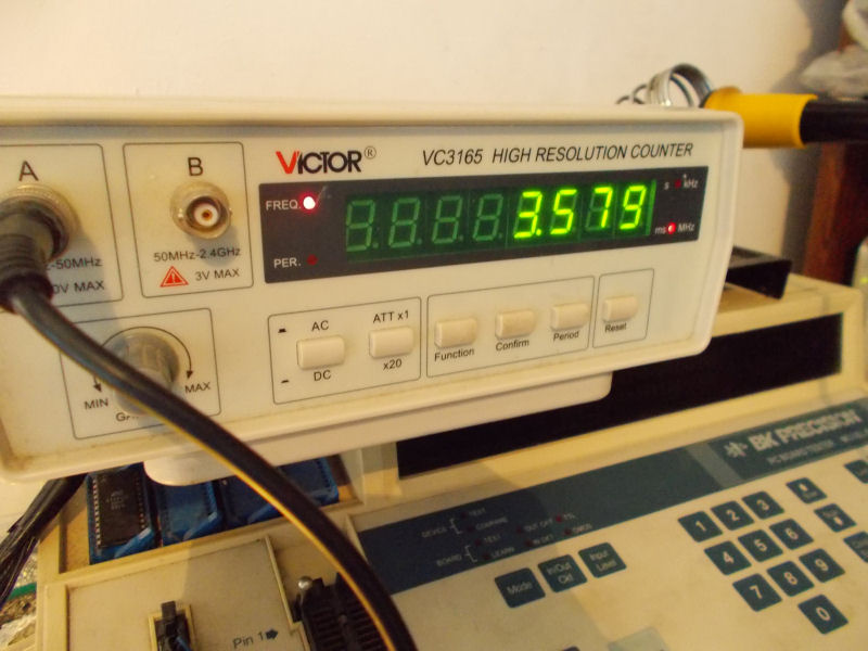
For first I checked its clock input pin and measured frequency was fine (3.579 MHz)  :

good_YM2151_clock

When I piggybacked a good chip on it correct music tempo was restored:

Replacing the chip fixed the issue completely.

 Posted by at 8:37 am
Sep 252015
 

This is one I fixed some time ago but still worth posting here.

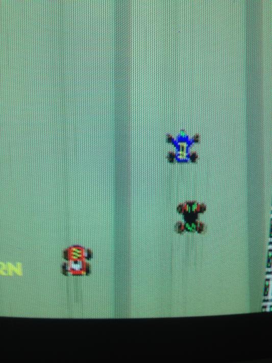
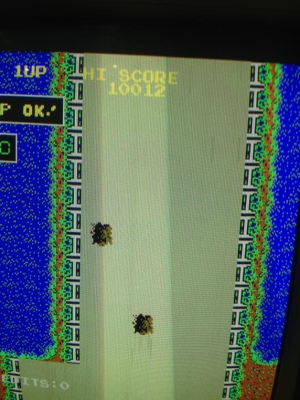
Problem 1: The display would exhibit streaks of grey lines mostly around sprites as the pcb warmed up & progressively get worse over the period. Symptoms would sometimes completely disappear after 10-15 minutes.

Note the grey lines around the sprites.

IMG_1387IMG_1424

After inspecting the board there didn’t appear to be any bad connections. I suspected an intermittent component fault.

I didn’t have any freeze spray so I cooled off suspect chips ( I used some ice wrapped up in a sealed plastic bag to avoid any leak )  and found cooling the transistor @ Q4 on the video board would reproduce the above problems. I replaced the faulty 2sc1815 transistor at Q4 on the video board which cleaned up the video sync signal.

Problem 2: Game boots sometimes, other times it does not start and boots to junk. 

Probed 6502 address pins, found that all were stuck high whenever the game failed to boot. All other signals looked OK. I tried substituting the main CPU for the sound CPU ( a  6502 as well ) but the symptoms were the same.

I traced the RST signal from the CPU to a 555 timer. There appeared to be a problem with pin 8 from the inverter at 9C to the trigger of the 555. Whenever the game booted to junk pin 8 of the inverter was floating & my logic probe was not registering the normal RST behaviour you would expect. I suspected a bad LS04 at 9C and planned to replace it.

Removed the LS04 at 9C. Pin 7 which is the ground pin was crushed under the IC. In other words it completely missed the plate thru hole ( it was blocked with solder ) during manufacturing and wasn’t making good contact with the ground pad. This game would have been faulty since the day it left the factory & explains the chip’s intermittent behavior.

Re-installed the inverter & re-tested with good results, no more booting to junk!

NANAO MS9-29S chassis repair log

 Monitor Repair Log, Repair Logs  Comments Off on NANAO MS9-29S chassis repair log
Sep 242015
 

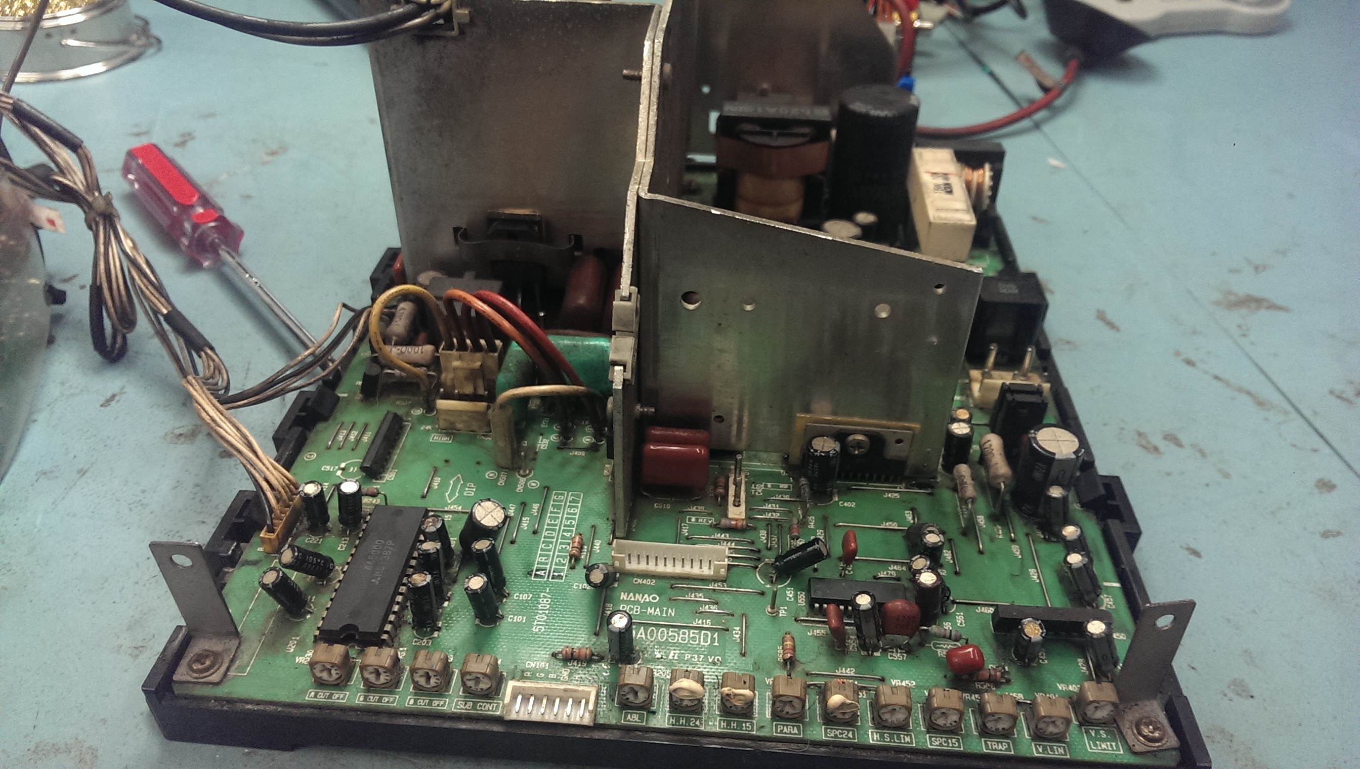
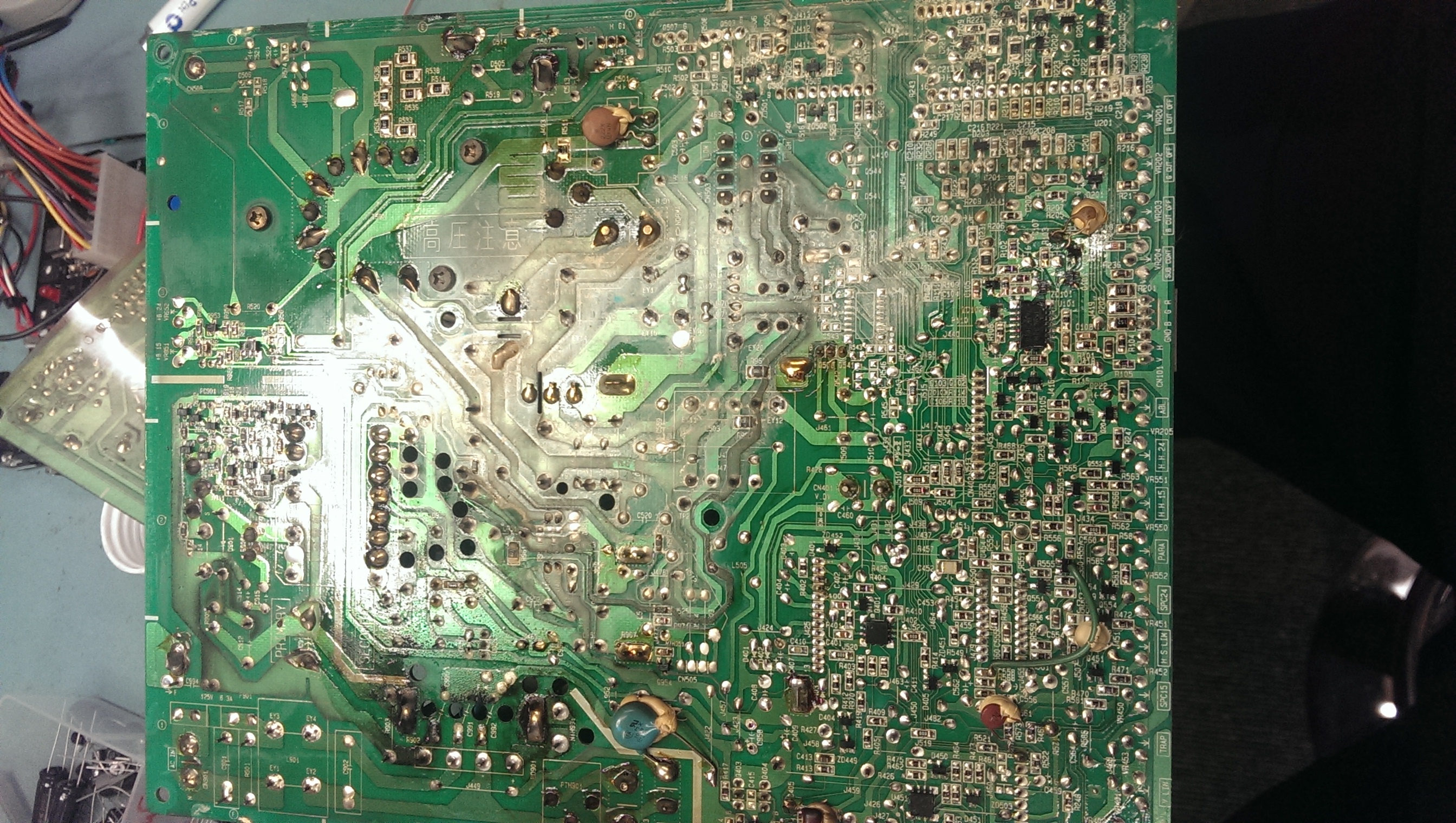
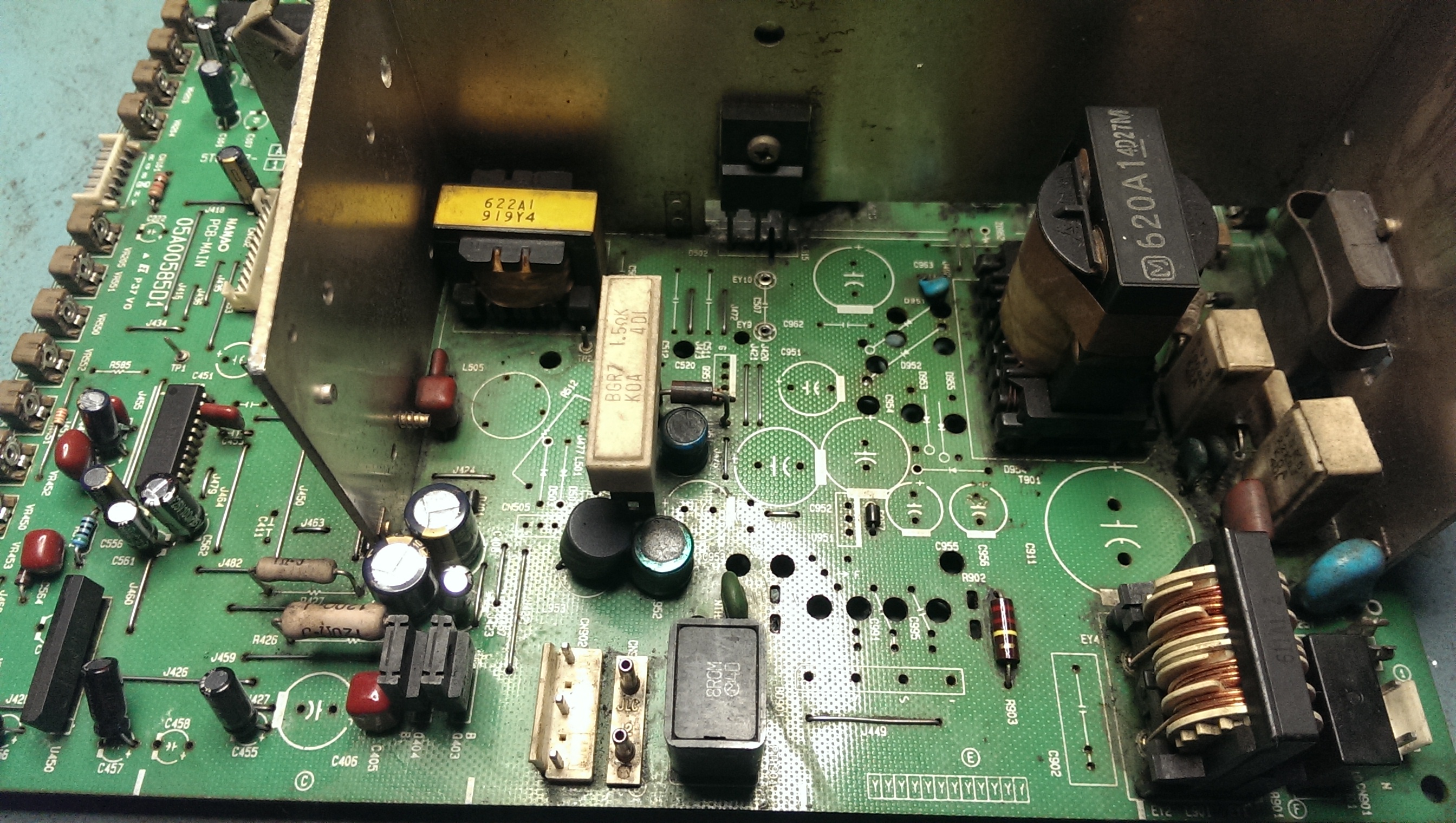
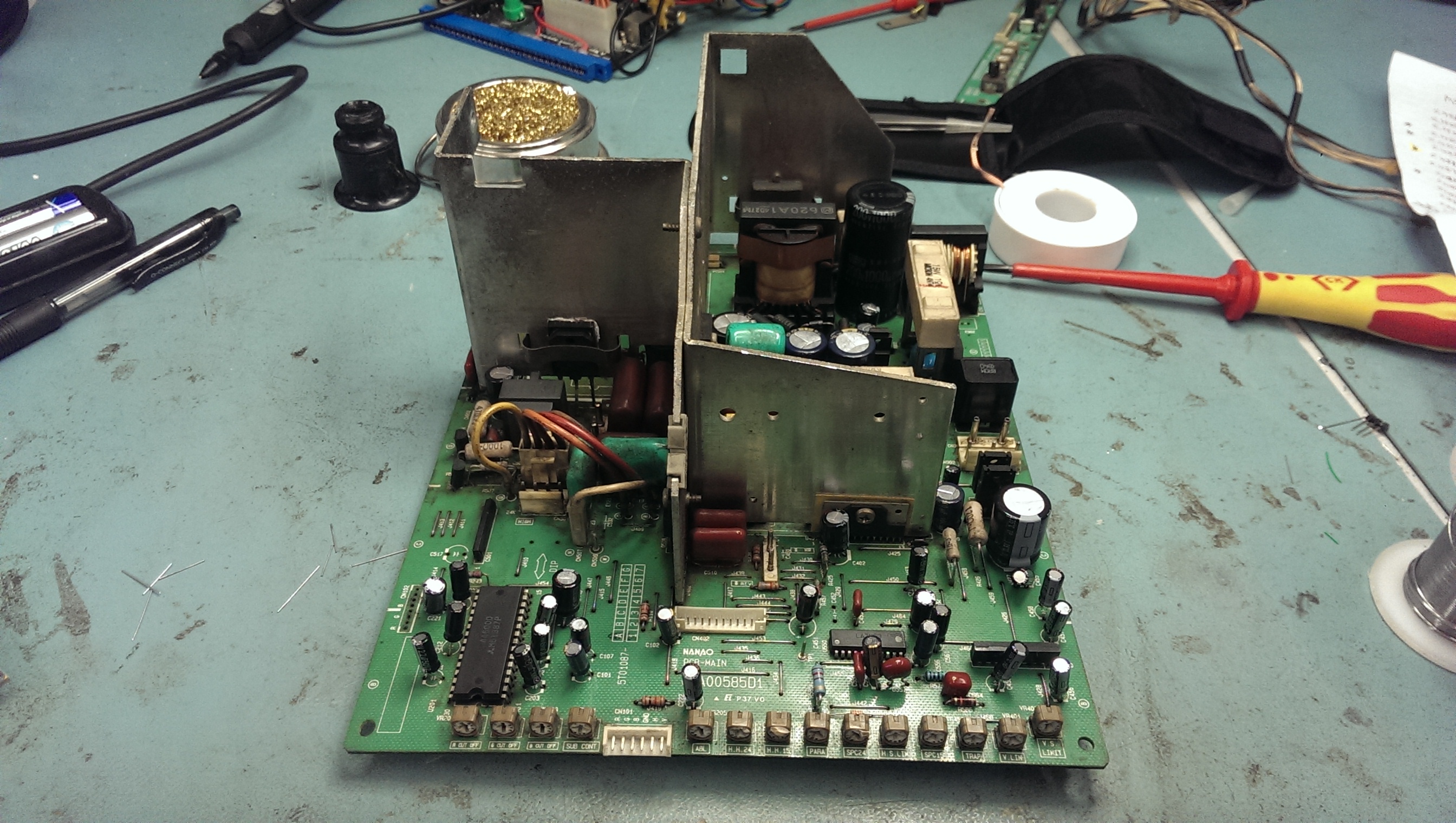
Had this chassis for a long time sat in my loft. Its never worked properly and testing it now it doesn’t do anything.
prework
underside

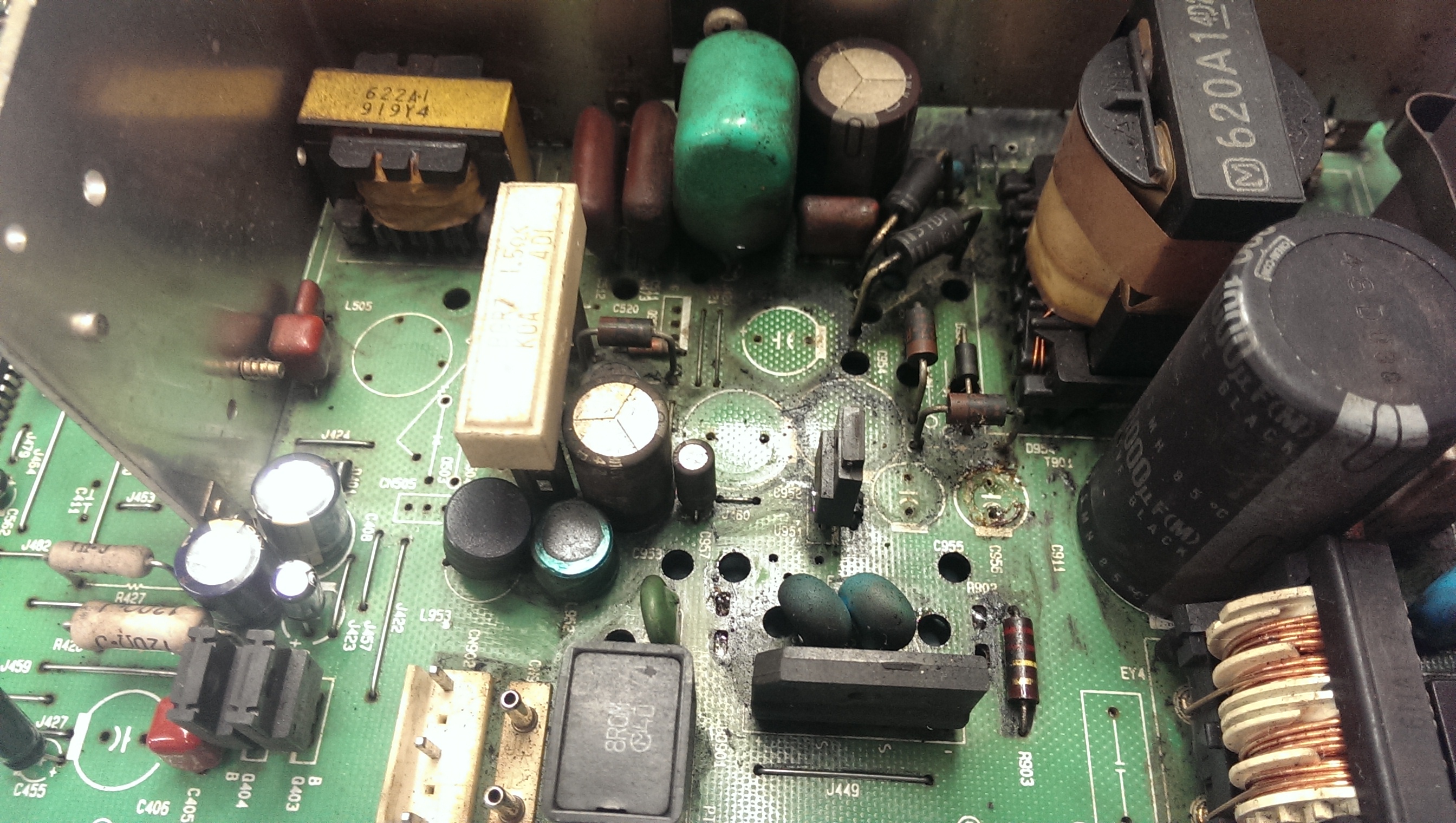
Taking a good look at the chassis showed that quite a few capacitors had been leaking and testing random ones with the ESR tester revealed plenty more bad ones.
As it was in a poor state and also seeing as it is my first attempt at a monitor repair I opted to replaced pretty much every cap I could and do a clean up along the way.

I removed all the caps and tested each one that came out. Here is a list of the ones I found to be bad:
C958 – 47uF 16v
C956 – 680uF 10v
C457 – 10uF 50v
C459 – 22uF 50v
C561 – 47uF 16v
C451 – 22uF 50v
C222 – 22uF 50v
C201 – 47uF 16v
C203 – 47uF 16v
C955 – 180uF 25v
C953 – 47uF 160v
C513 – 10uF 250v
The electrolytic capacitor on the neck board was also bad.
Also found resister R585 (120k ohm) was damaged.

leaked
I ordered up the caps and cleaned up the PCB.
cleaned

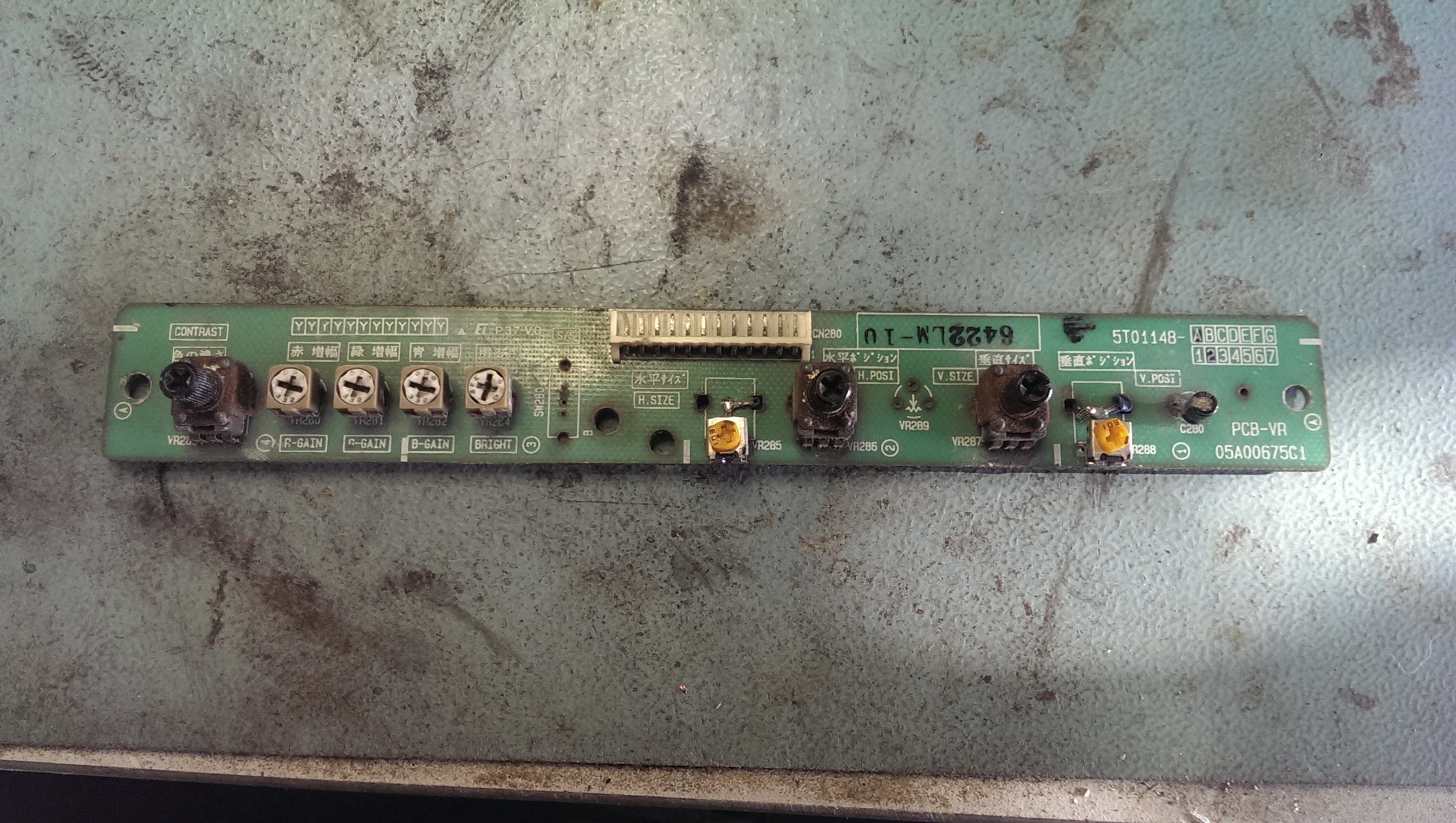
I then turned my attention to the remote board.
remote1

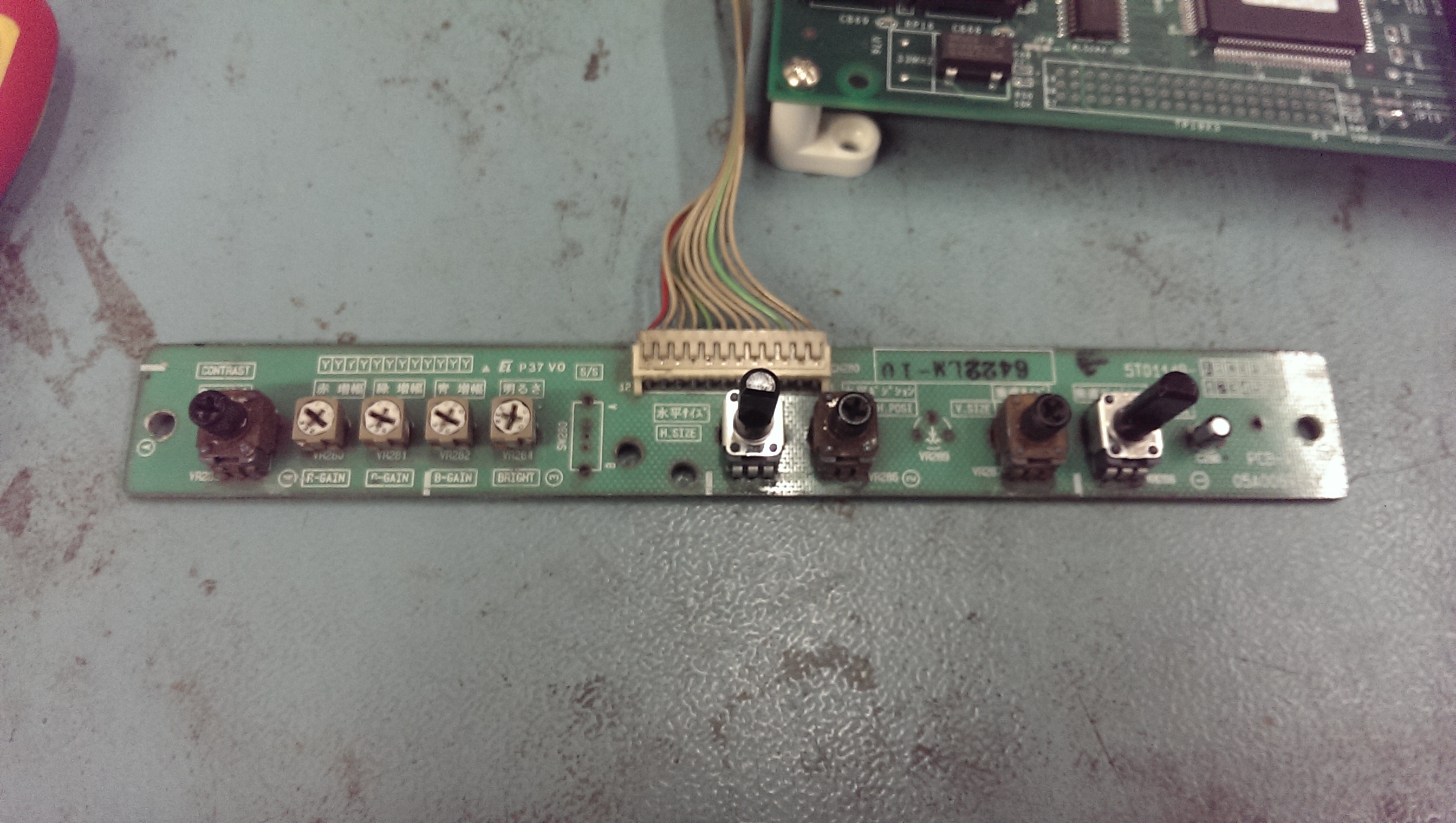
This had two pots missing but had a couple of different ones hacked in their place and the smoothing capacitor was also leaking. I found some 10k Alps potentiometers on eBay so ordered a couple of those too.
The existing pots look in bad shape but they check out OK and operate quite smoothly so ill leave them alone for now.
remote2

A few days later all my stuff had arrived from Mouser and I was ready to put this thing back together.
done

I fitted it back into my spare 29″ tube and fired it up for the first test.

With a bit of tweaking I got the decent picture. The photo doesn’t really do it justice but I’m pleased with the results.
picture1

picture2

 Posted by at 11:59 am

Shadow Warriors repair log

 PCB Repair Logs, Repair Logs  Comments Off on Shadow Warriors repair log
Sep 202015
 

Just a quick fix for a Shadow Warriors PCB I had since many years but never looked at:

Shadow Warriors_PCB

Gameplay was fine but all the backgrounds GFX were scrambled and messy:

bad_backgrounds

This is the part of circuit which generates the backgrounds, located on video board:

backgrounds_circuitry

Luckily EPROMs and RAMs were socketed so I first tested the latter and found a bad one @3D (a Toshiba T5563 pin to pin compatible to a generic 6264) :

T5563@3D

Replacing the bad chip was enough to clear the issue.

backgrounds_fixed


 Posted by at 11:21 pm
Sep 202015
 

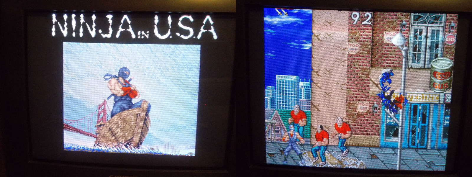
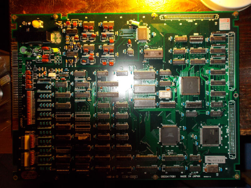
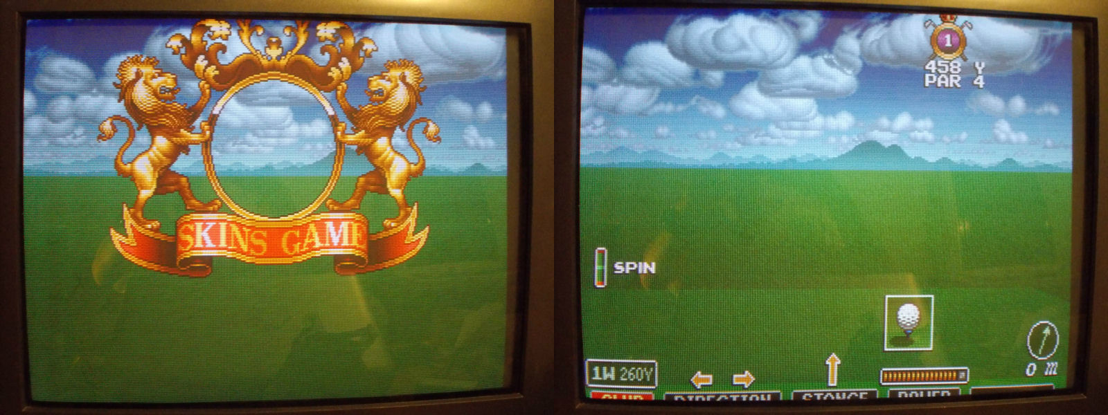
I got this Major Title 2 PCB for cheap from ‘Smitdogg’ of MAME team:

Major Title 2_PCBX i

He said me board had some GFX issues.Actually when I powered it up I got no sprites at all:

no_sprites

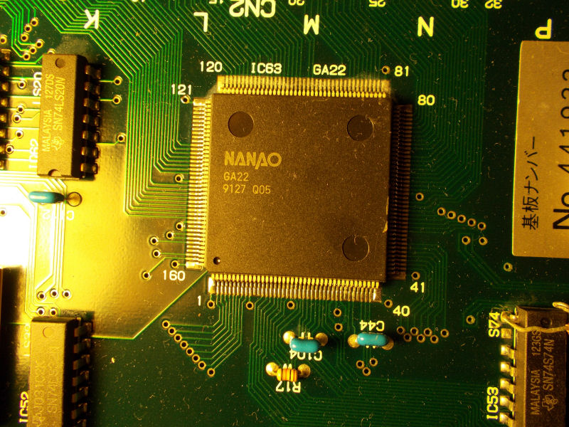
For first I checked the sprites EPROMs with my logic probe and found no activity on all pins.These four sprites MASK ROMs on video board are addressed by the ASIC “GA22” on CPU board :

NANAO_GA22

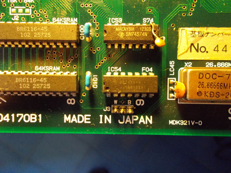
I probed it and all its pins were silent too.I tried to reflow it without luck, sprites were still absent.Then, looking at the board, I noticed an open jumper ‘J3’ right hear the GA22 ASIC:

J3_open_jumper

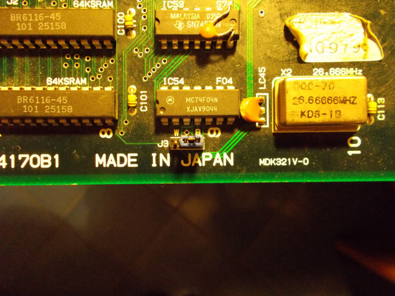
Looking at other M92 CPU boards I could see that this jumper was always closed to position ‘B’ (so with central and right pins shorted together).So I did it on my board too:

J3_closed_jumper

and sprites were magically restored!

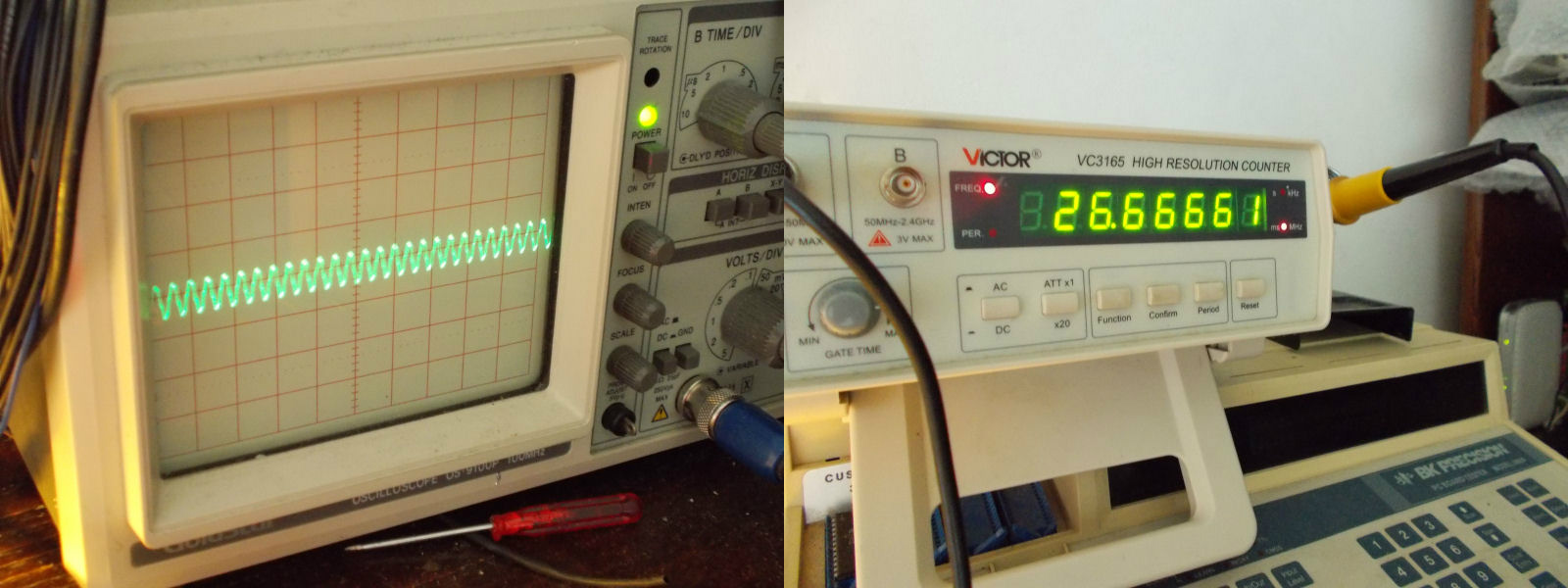
Now the technical explanation.The jumper is actually for selecting which clock signal must be delivered to the sprites generator ASIC “GA22”.If closed in ‘B’ position, ASIC will receive a clock signal of 26.6666 Mhz (which is the correct value for most of M92 games) :

26.66666_signal

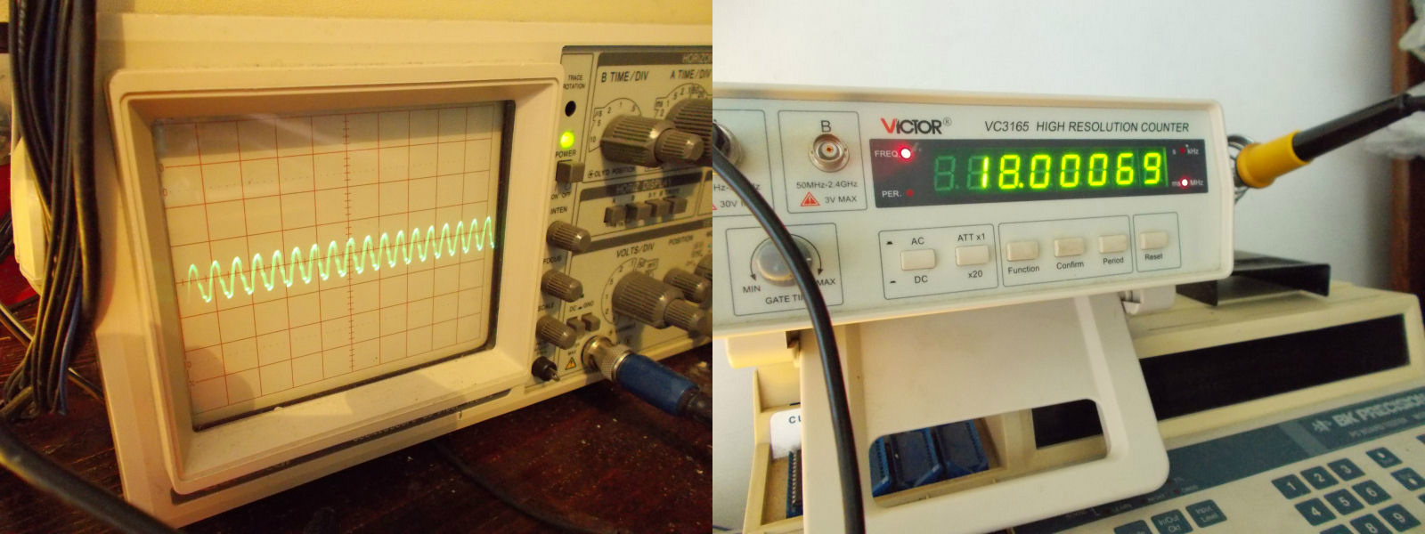
If closed in ‘W’ postition, the ASIC will get a 18.000MHz signal (no sprites with this configuration) :

18.000MHz_signal

Last issue to fix was some audio background noise:

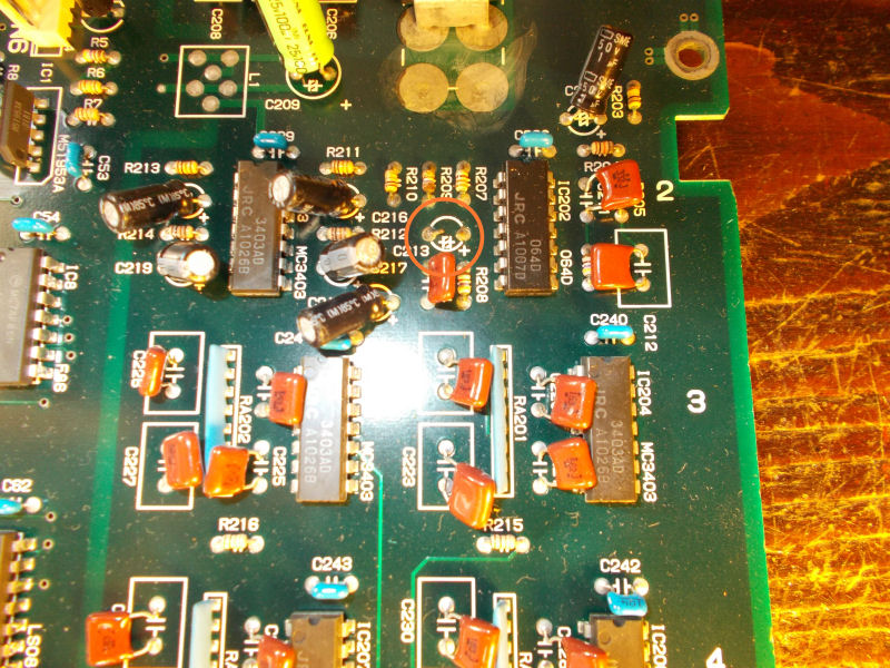
I quickly traced it to a missing 47uF 16V electrolytic capacitor @C213 in analog sound section:

missing_C213_capacitor

End of job.

 Posted by at 10:17 pm