Got Muddymusic’s Helifire (not to be confused with Hellfire by Toaplan) to look at.
He bought the original cocktail cab and on first power up was met with nothing but a “loud noise”.
His initial checks were that his +5v line was reading +2.5v and sent me the PSU to work on.
Now due to the various AC voltages required to actually use the PSU I was unable to do any real testing so instead he sent me the transformer and PCB too.
Now I could start checking the PSU I found that the +5v line was indeed around +2.5v. While I had the PSU powered up I suddenly got a +5v voltage output and it was pretty solid.
I couldn’t check to see if the game was running at this point as I had no way to connect the game to a monitor so I probed the video out pins with the scope and everything appeared to be at least what I expected.
While I had the PCB hooked up to load the PSU I momentarily saw the voltage on the +5v line would drop to +2.5v and then to my horror rose up to +8v!
I immediately powered it down and it has not been back on since.
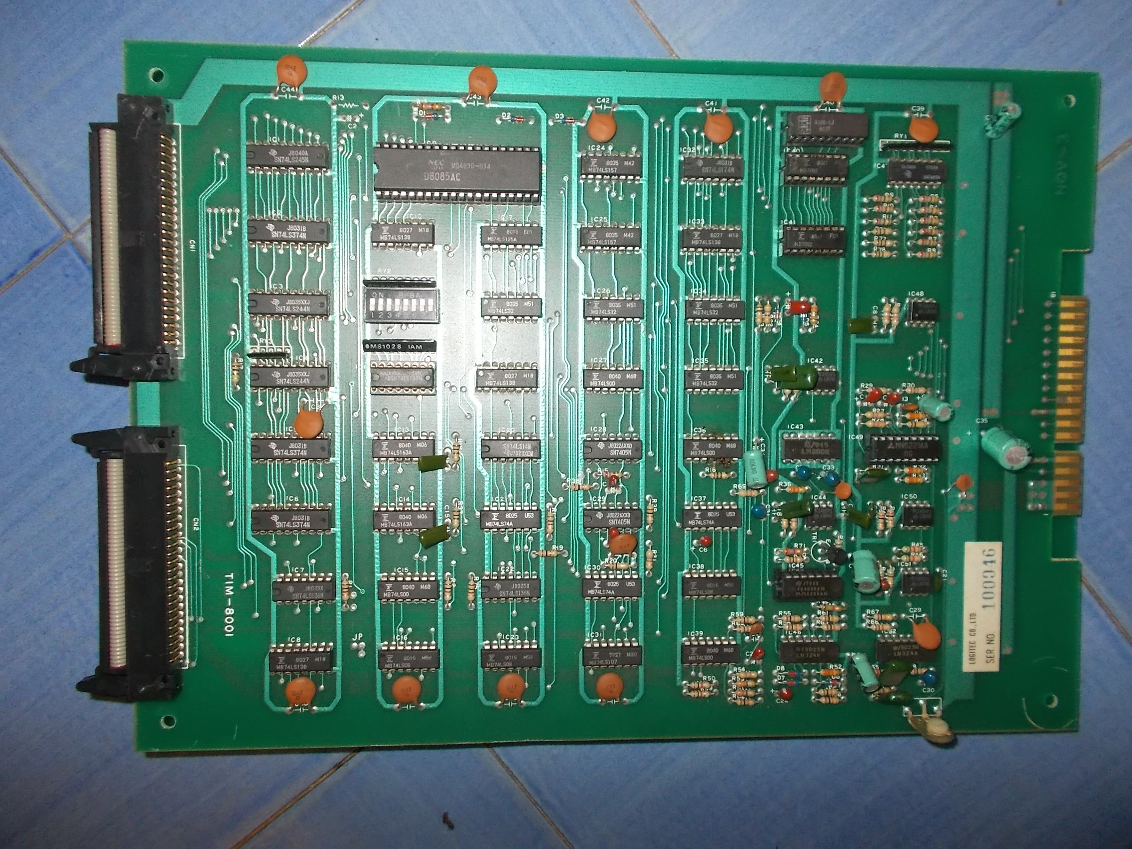
I opted to hook it up to a switcher but when I did I noticed the video sync output was missing. I guess the PSU took it out. I also noticed the 8080 CPU wasn’t running either and was getting quite hot.
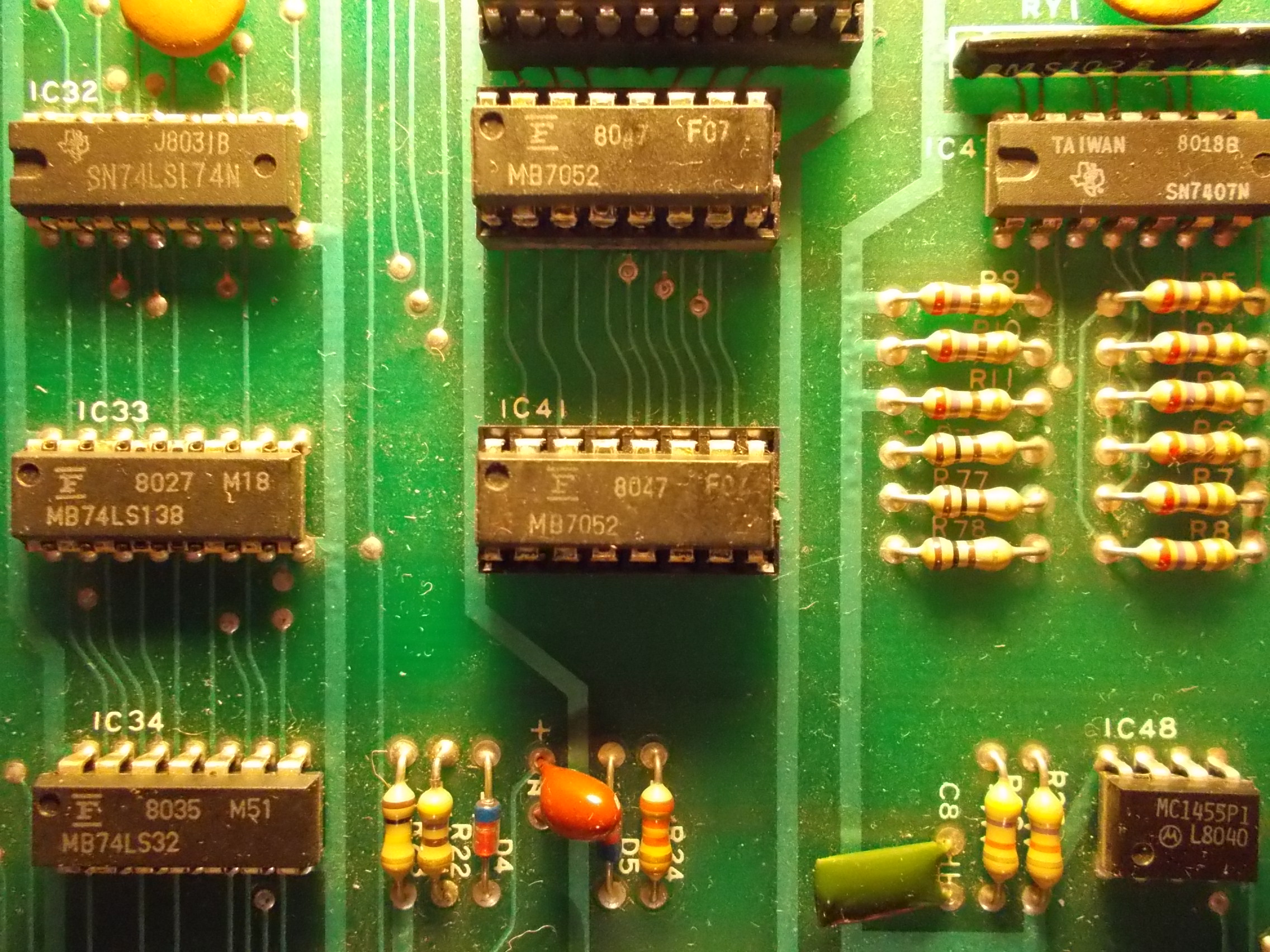
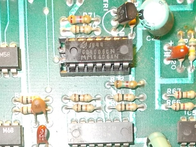
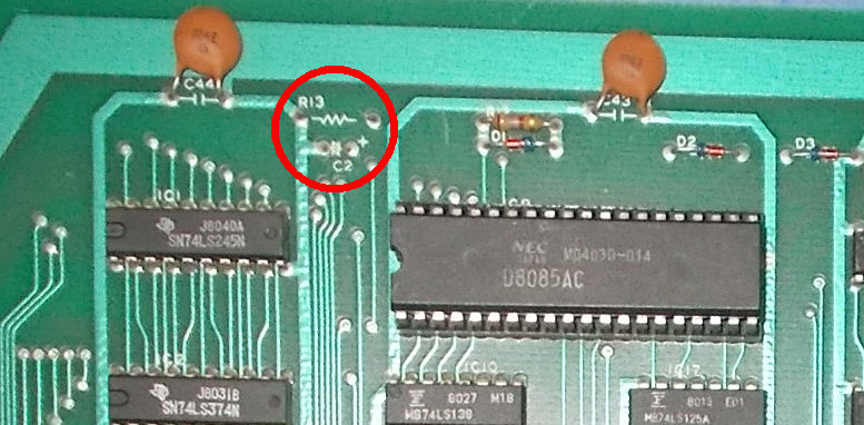
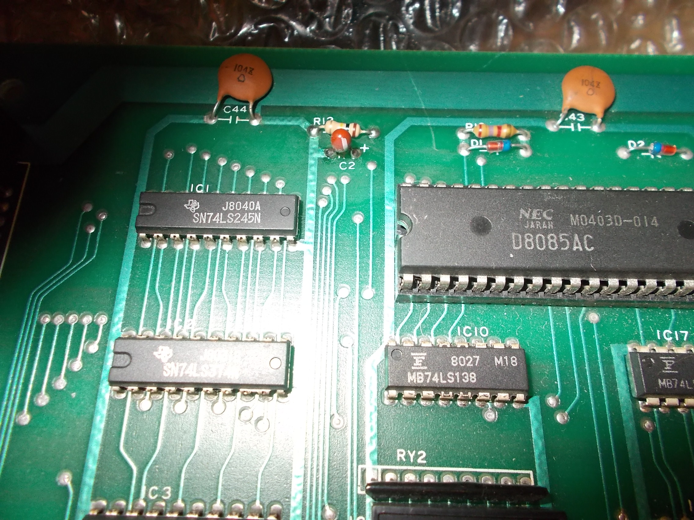
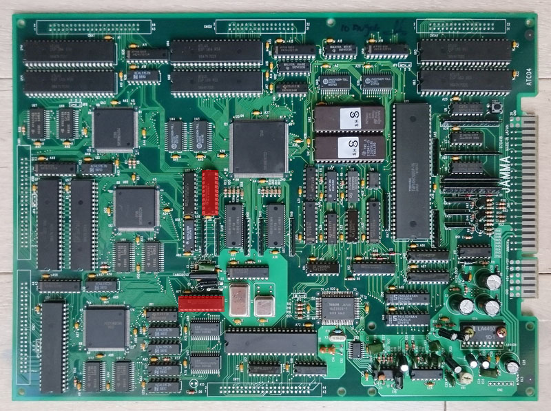
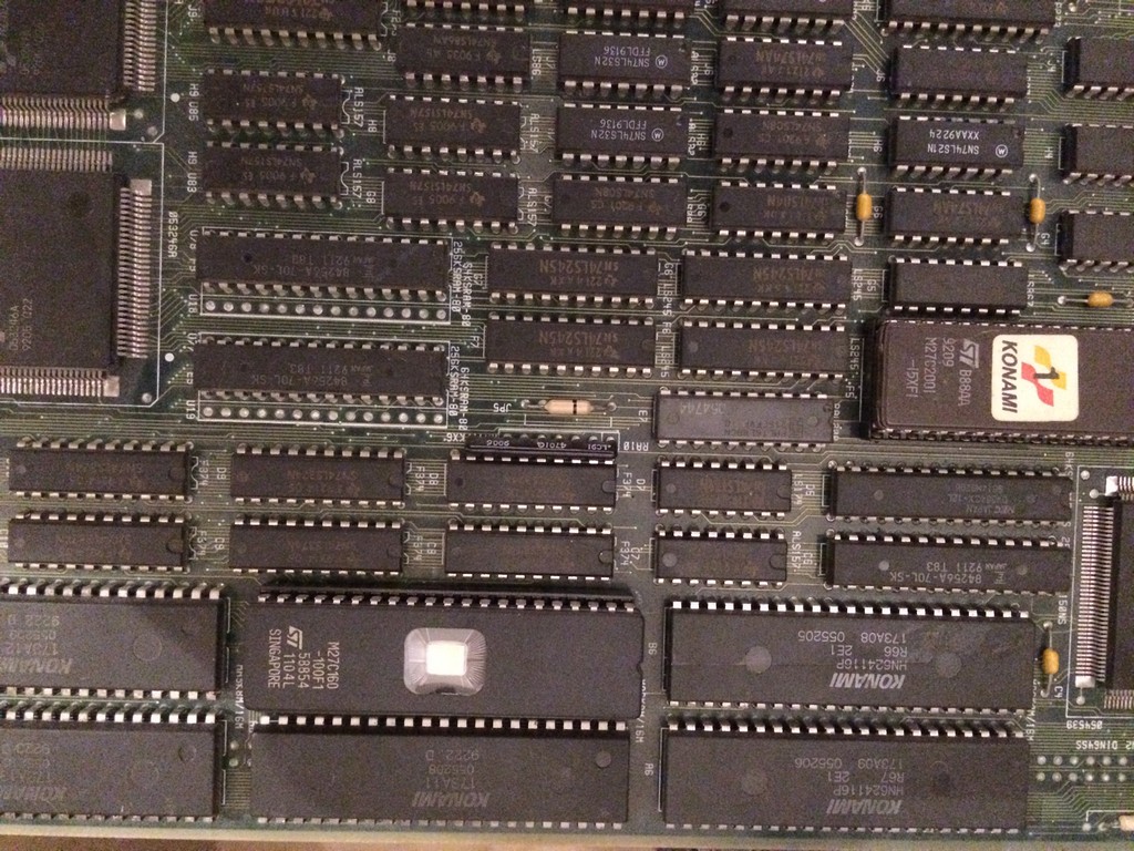
I’ve got access to a thermal camera right now so checking the PCB with that revealed the 8080 in the top right corner was way too hot.
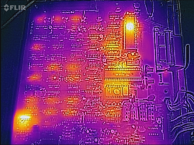
I had no spare 8080 CPU’s so placed an order for a couple and moved onto the missing SYNC signal.
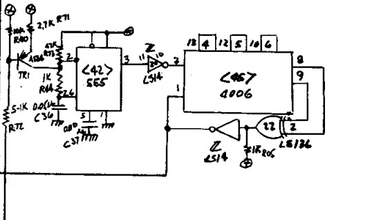
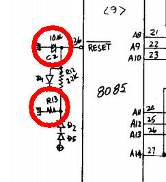
Working backwards from the SYNC output and using the schematics available I quickly found the 74LS109 at location 3B had stuck outputs despite having good inputs and a healthy clock signal.
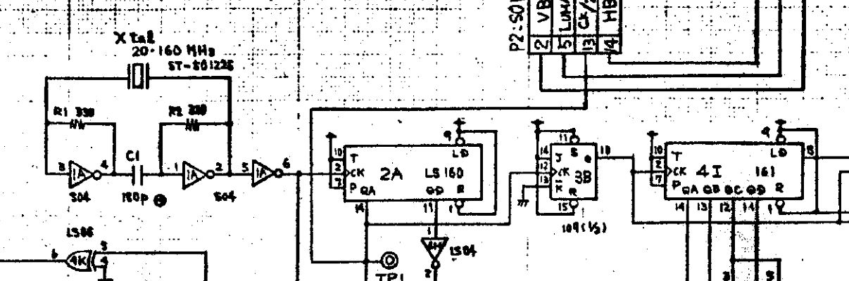
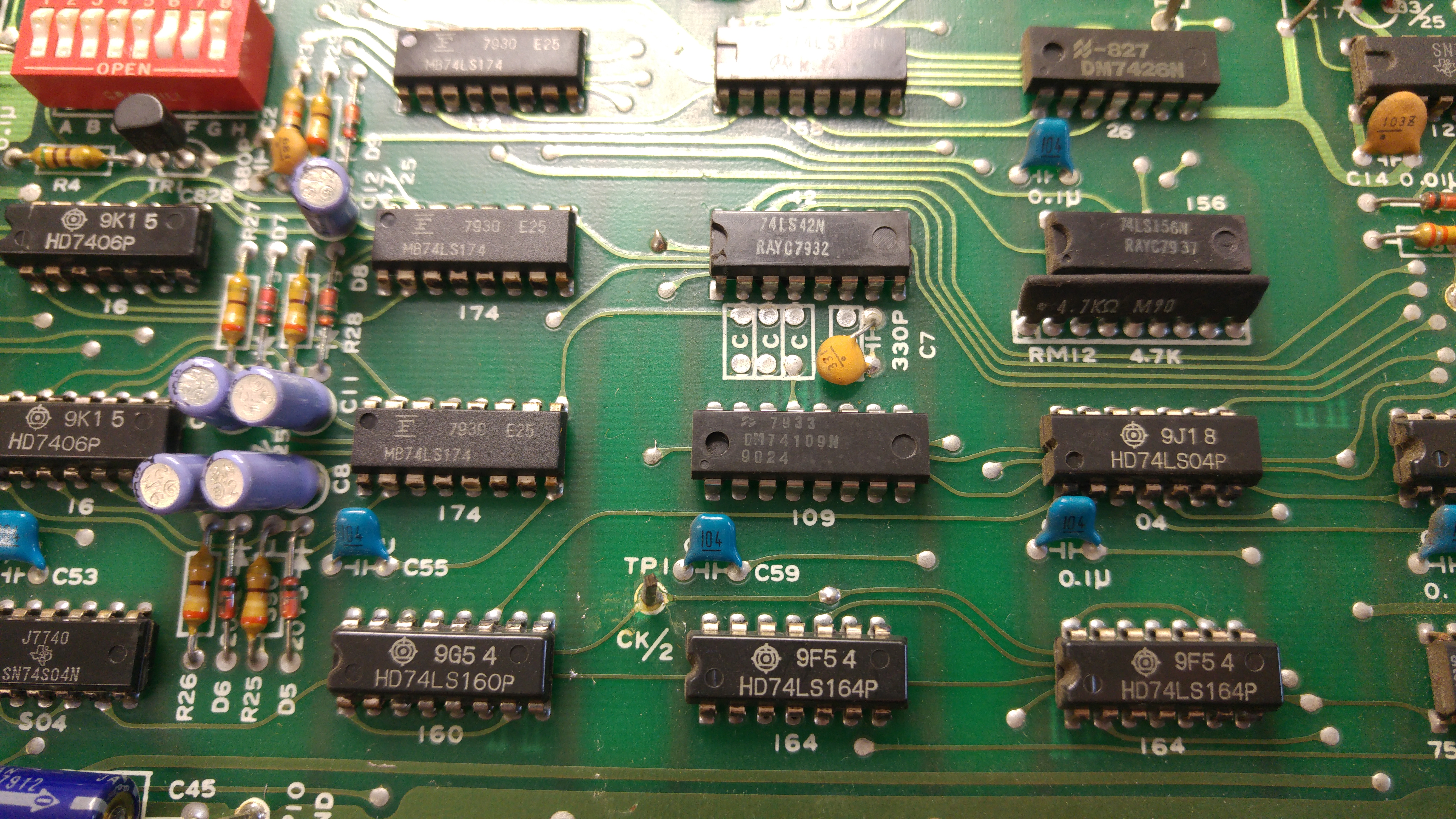
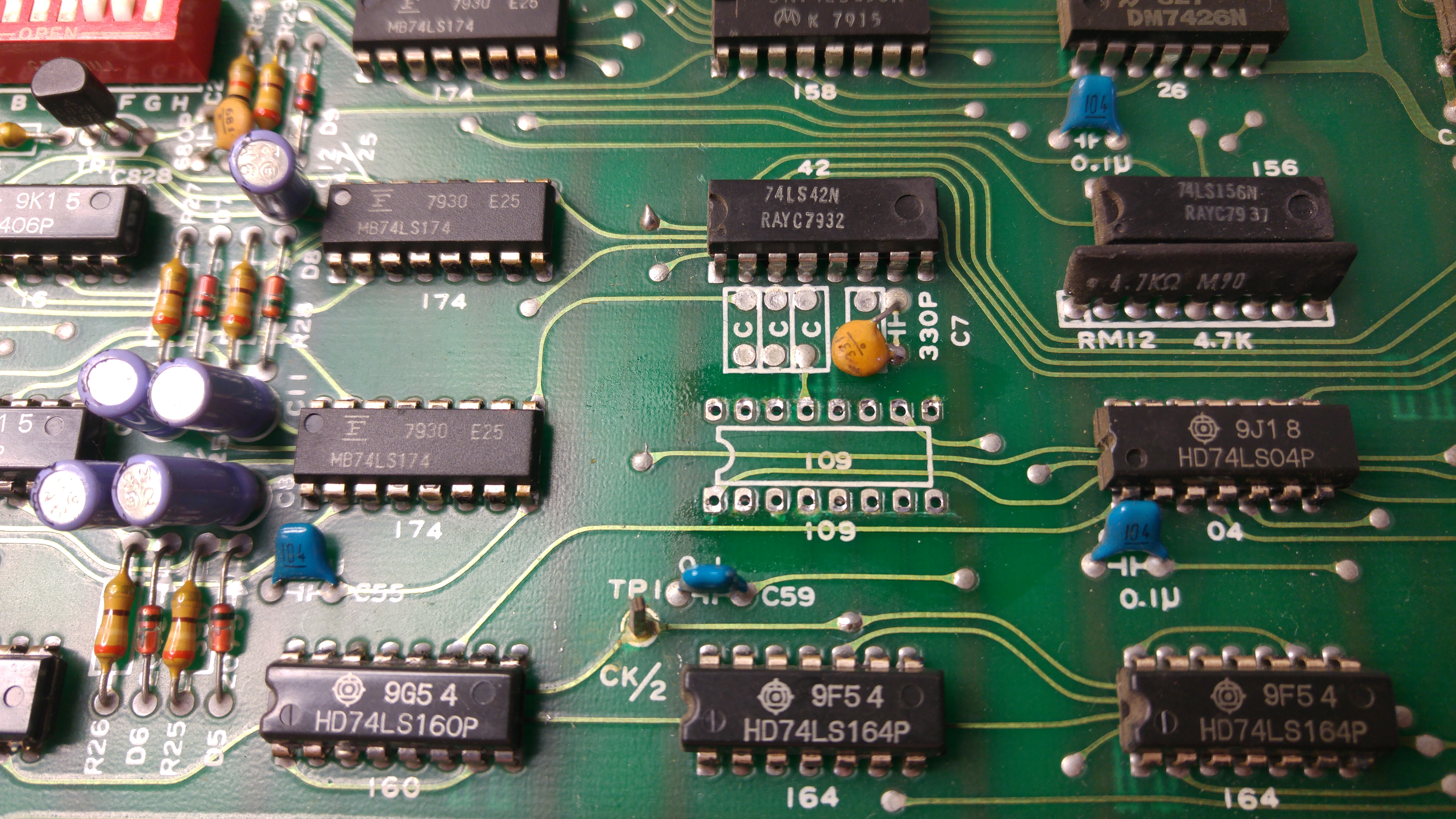
Replacing this chip gave me back my signals.
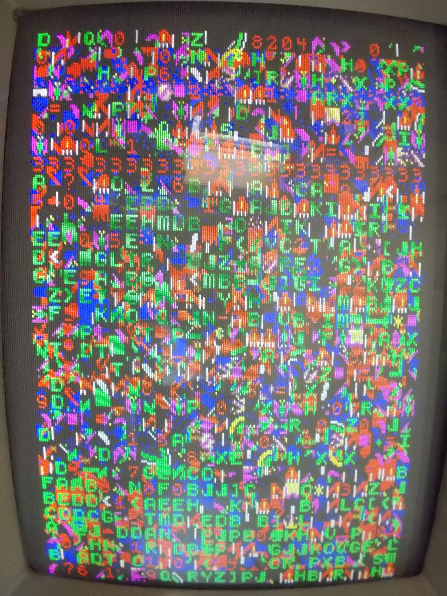
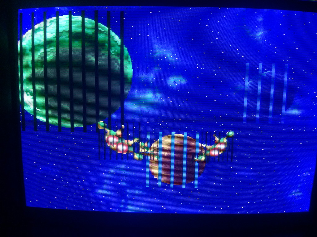
A week later my 8080 CPU’s arrived and I managed to get the video output hooked up to my Commodore 1084D monitor to test.
At the time I didn’t even realise that the game was black and white and uses a colour overlay so I was initially confused by the colour in the game but Muddymusic soon put me right on that.
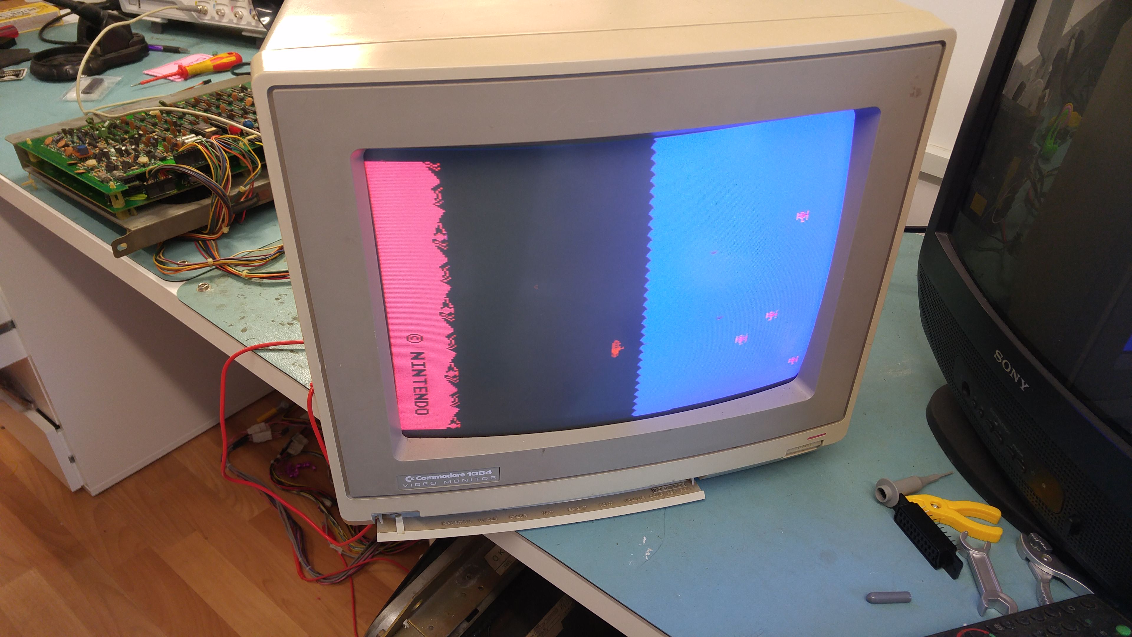

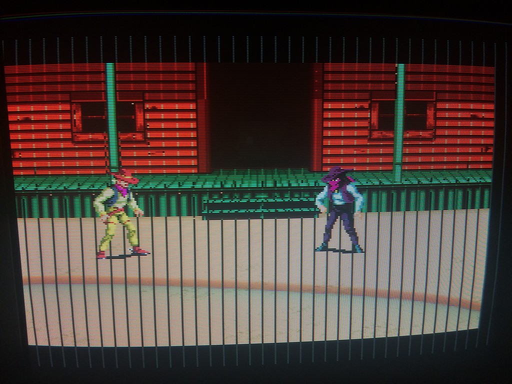
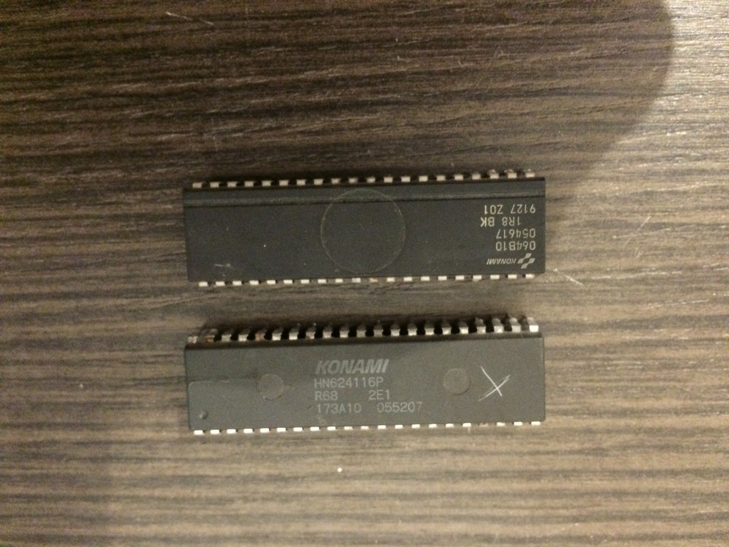
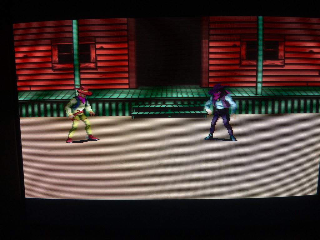
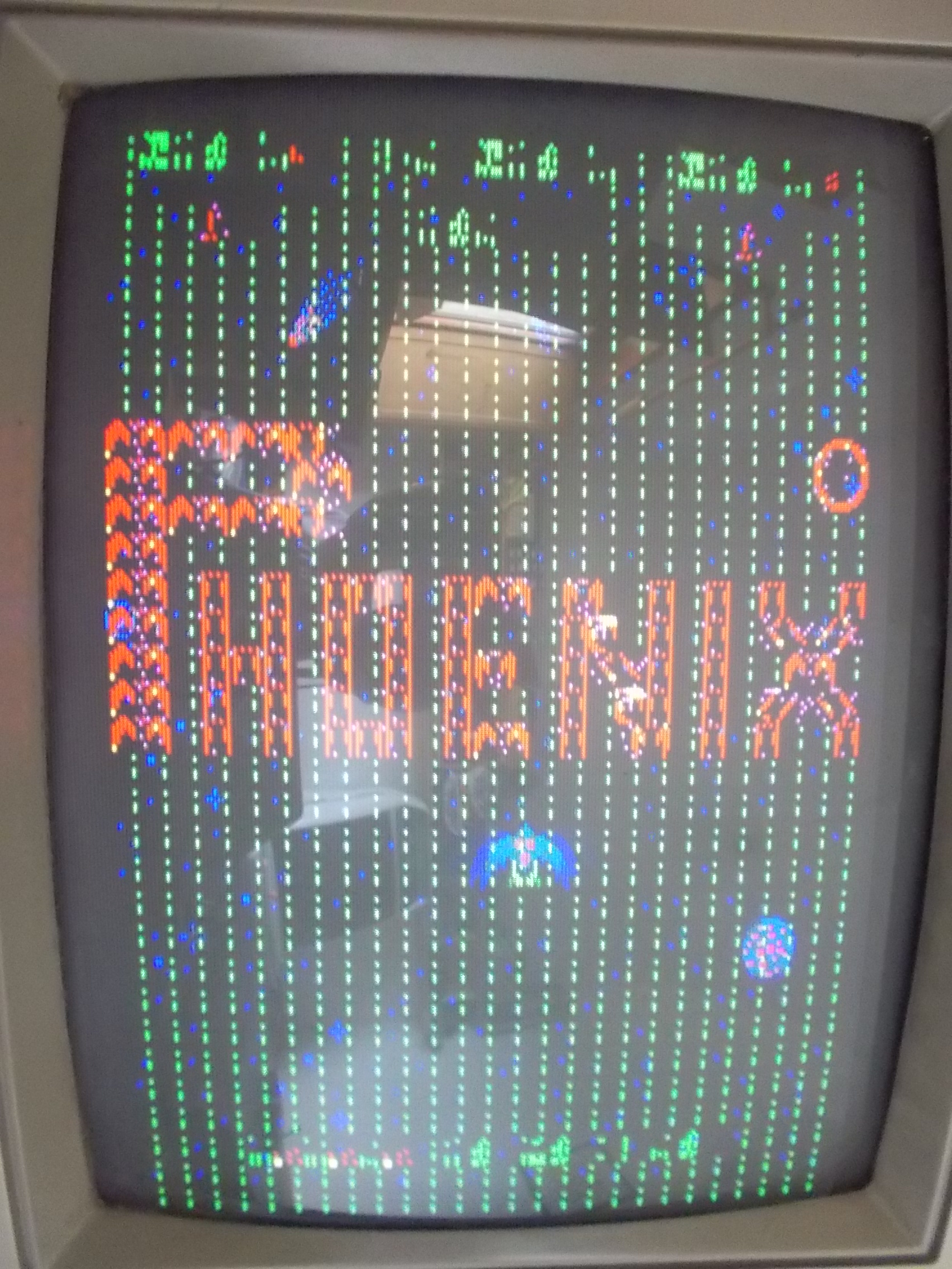
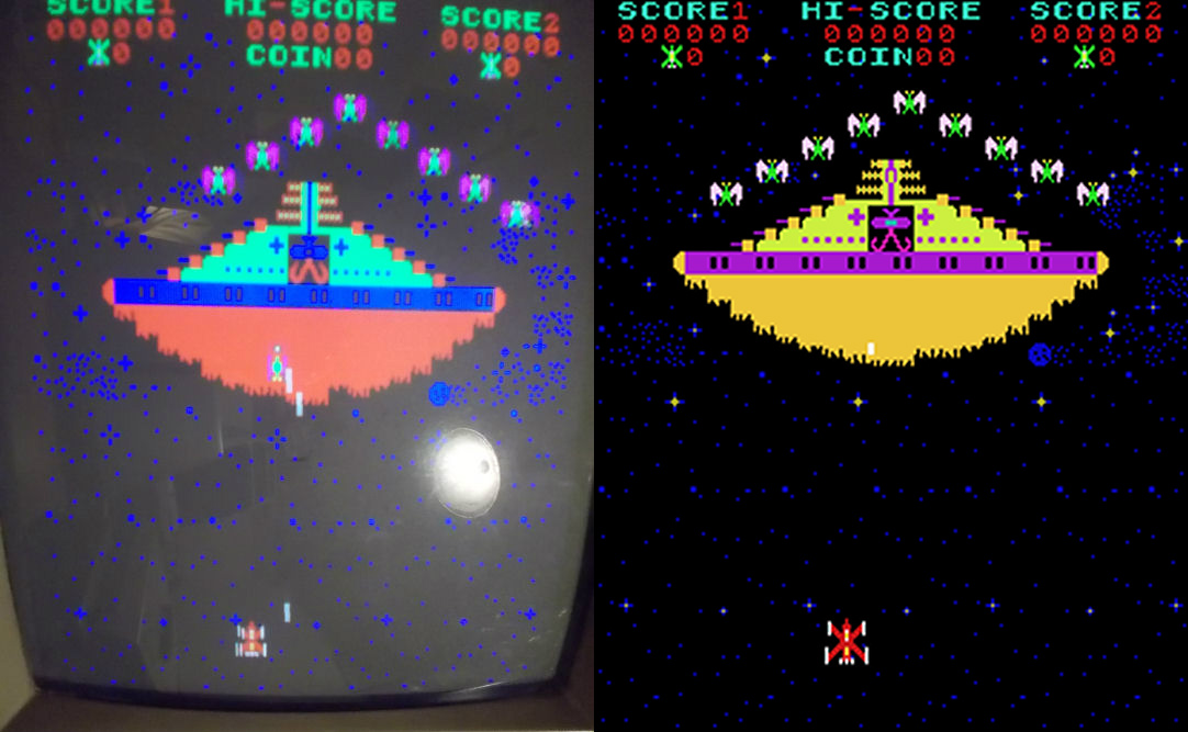
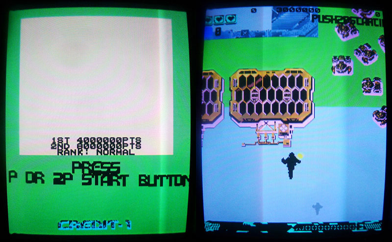
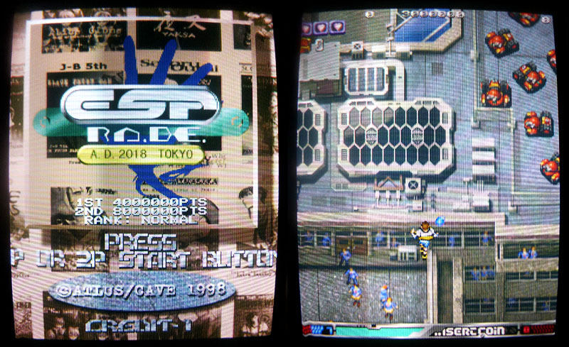
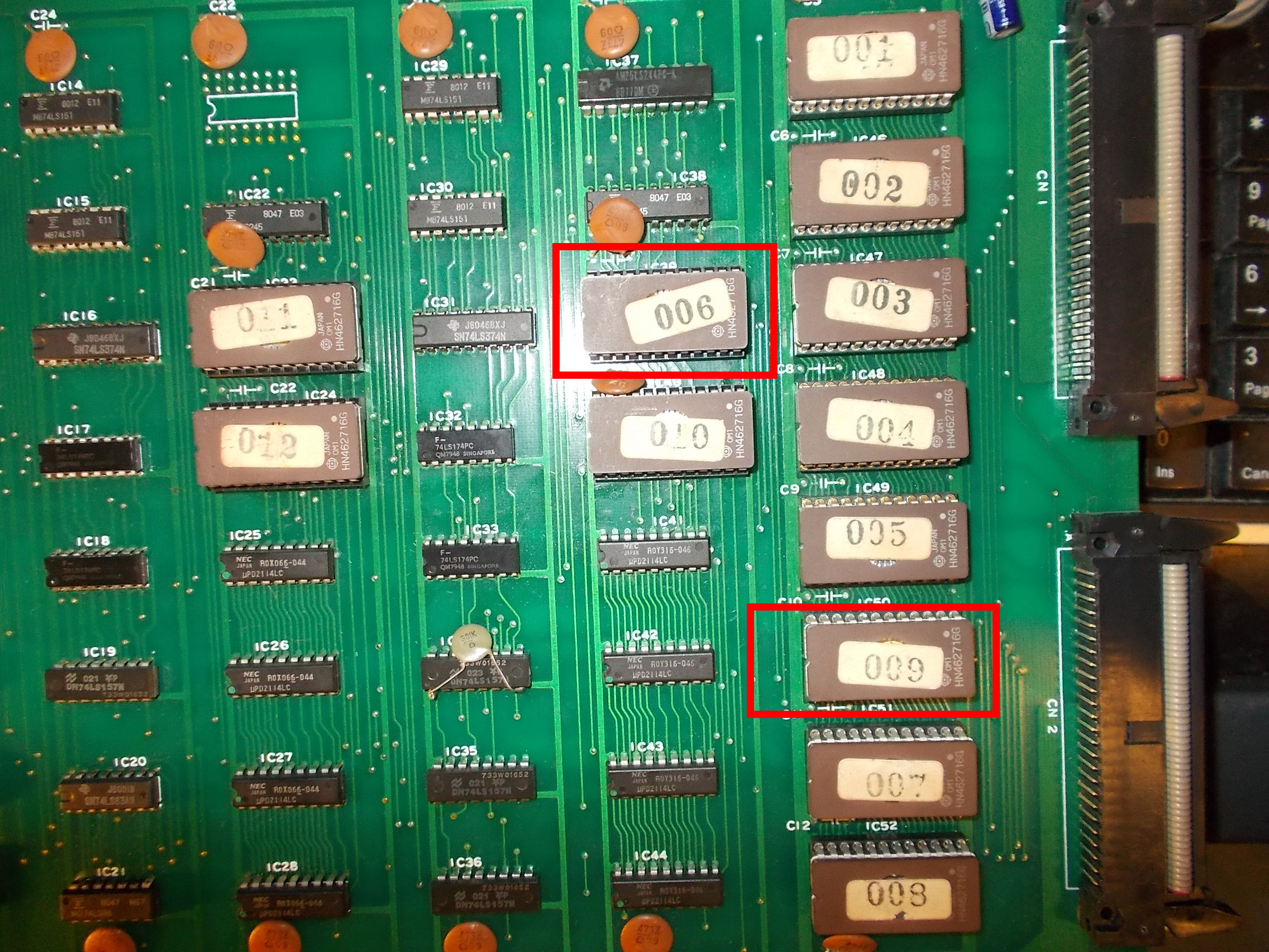 Putting the two ROMs in right location restored the graphics but colors were wrong, here’s a comparison with a MAME screenshot on the right: