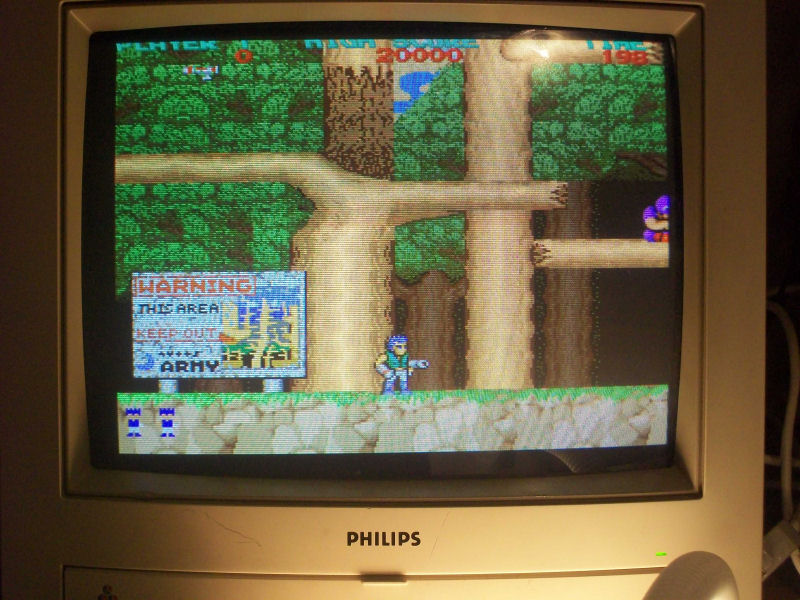
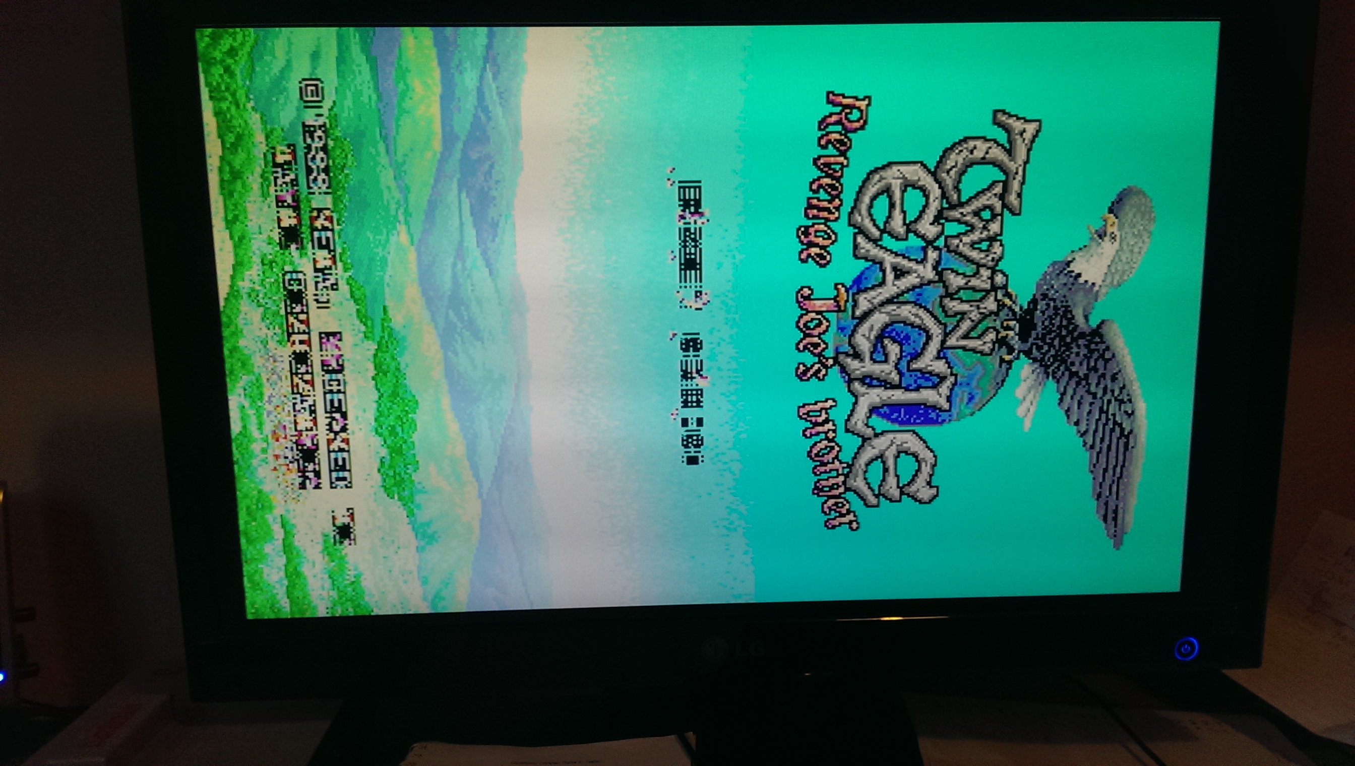
Got this original Konami Bucky O’ Hare PCB for quite some time but I never looked at:
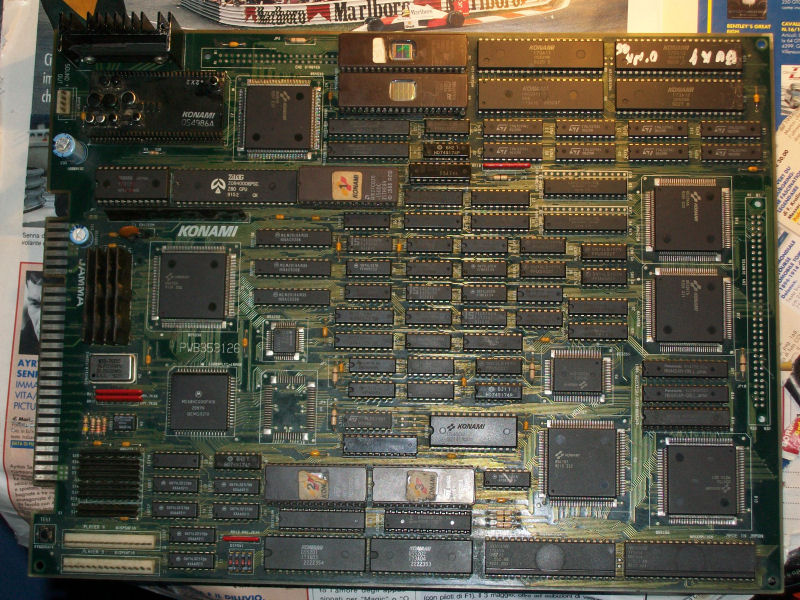
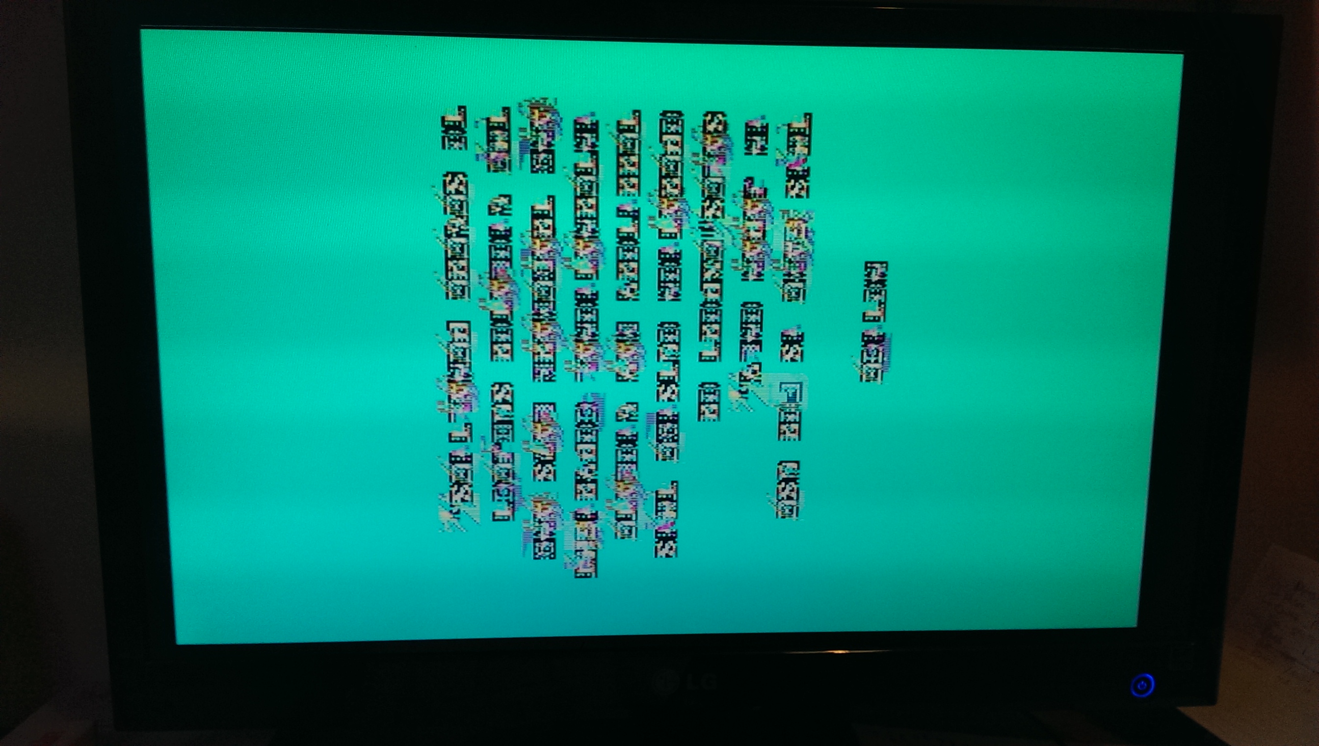
Once powered on it displayed good graphics but loud, scratchy and distorted sound.Everyone in the arcade world knows that this kind of PCB use an hybrid custom sound module, in this case it’s the one marked ‘054986A’ (other games like X-Men use the ‘054544’ one) which is famous to go bad (in particular its SMD electrolytic capacitors will leak sooner or later damaging tracks).Well, with these premises, I decided to do a full recap of the module following this chart:
https://jammarcade.net/images/2024/05/KONAMI_HSC.pdf
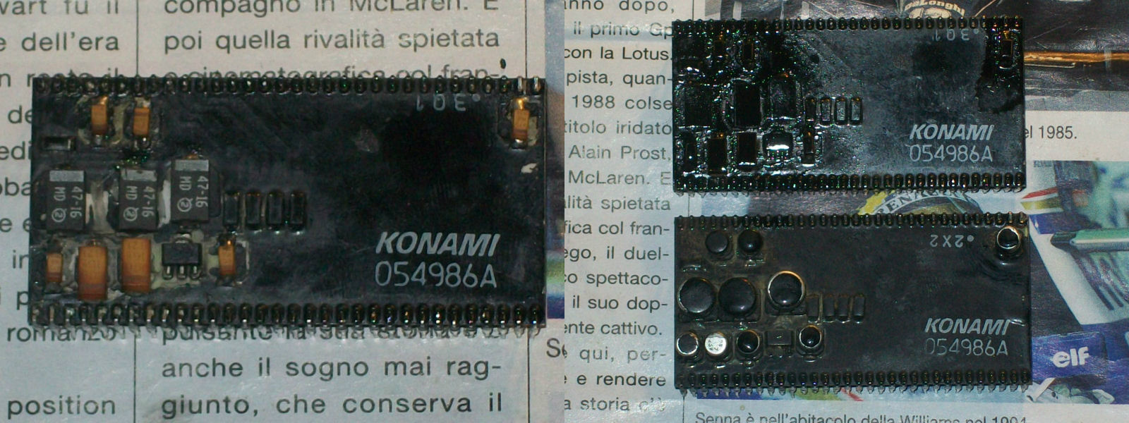
I opted for a different solution.I used tantalum SMT tantalum capacitors instead of electrolytic through hole or SMD ones.Why will you say?Because tantalum capacitors are extremely reliable, they don’t suffer from leakage and have a lower ESR.Last but not the least, they are also more elegant than electrolytic one like you can see in this comparison at the end of my recap/repaint job :
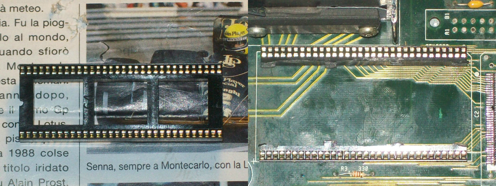
Anyway once powered on again the board I got same sound issues.I know this custom module has additional circuitry also on the underneath.So, I was force to desolder again the module but this time I socketed it using a 64 pin SDIP (shrink DIP) socket divided in two stripes for an easy future maintenance:
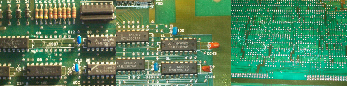
After desoldering it, I found this scenario:
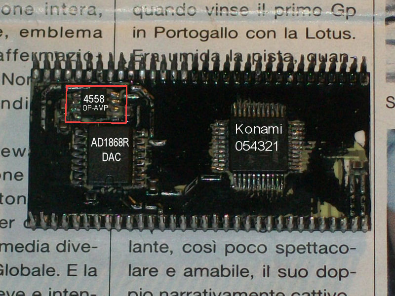
In particular there is a QFP Konami ASIC marked ‘054321’ (probably a MCU which controls the entire sound system, infact if you run the PCB without it the RAM/ROM test will show error on all related sound components -RAM, ROM, 74LS245 and ASIC ‘054539’).Besides there are also a JRC4558 OP-AMP (LM358 compatible) and a AD1868R (Dual 18-Bit Audio DAC), all in SMD package.
Judging from the issue I started to suspect about the 4558 OP-AMP.So, I borrowed one from a faulty PCB. After a quick soldering I turned on the PCB again and..the sound was back, crystal clear as it should be.Mission accomplished.