Jul 262014
 

I recently sold this PCB but after a week I was told the board had developed a fault.
The fault showed up as “RAM NG 10” at boot-up and there was some issues with the sprites.
IMAG0738

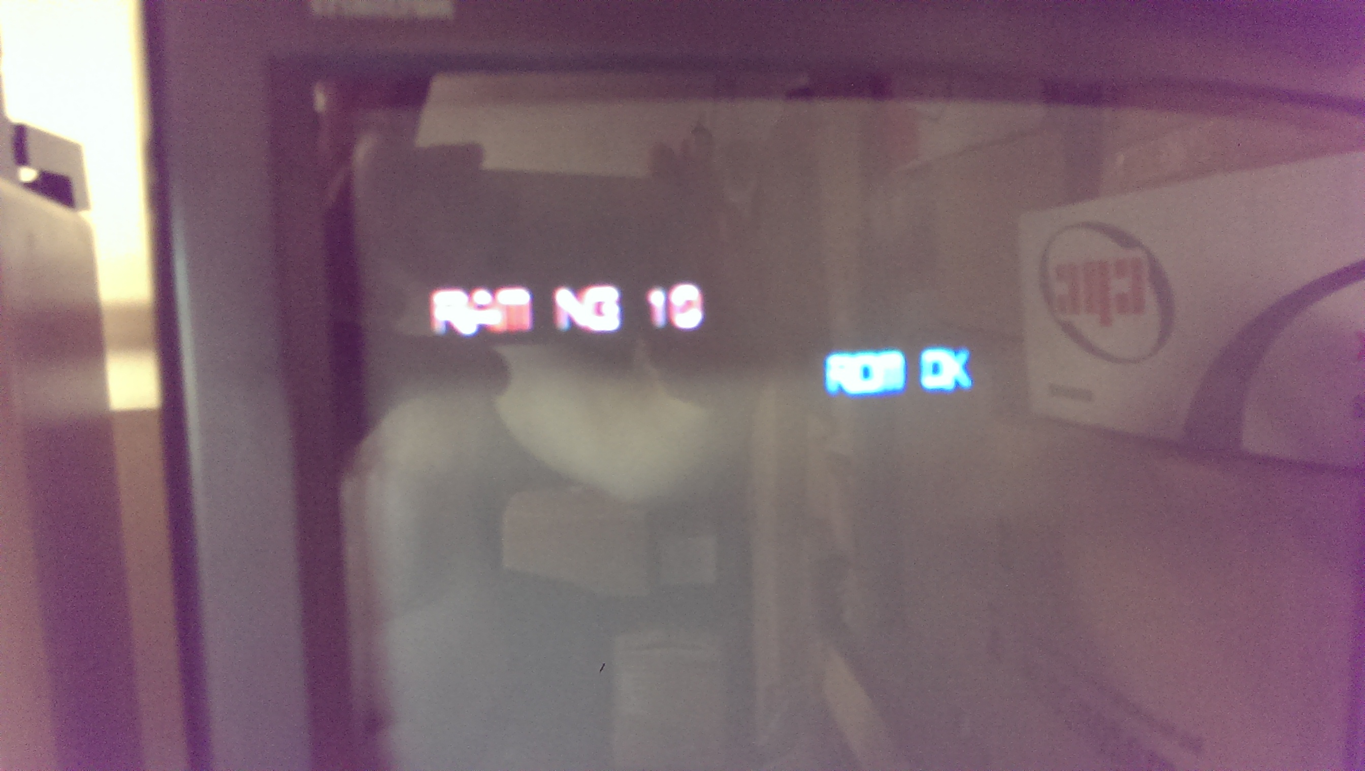
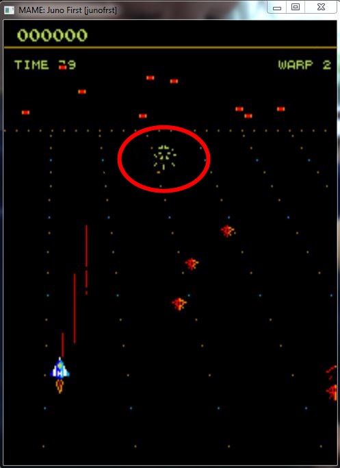
There is absolutely no logical meaning to the error message so using MAME I started corrupting different RAM values during it POST to see what RAM errors were flagged up during which memory writes.
Originally I couldn’t understand how the awful V30 CPU worked. Without knowing how it worked I was unable to use the MAME debugger effectively. Charles MacDonald came to my rescue and told me how the V30 addresses were set. Thanks very much to Charles.
You can see the outcome of that exercise in THIS previous post.

So now I knew for sure that the fault was with the sprite RAM. Now the next challenge, which RAM chip is the sprite RAM?
I originally tried shorting some address/data lines on RAM chips to see if any other errors were flagged but strangely it didn’t show anything else at all.
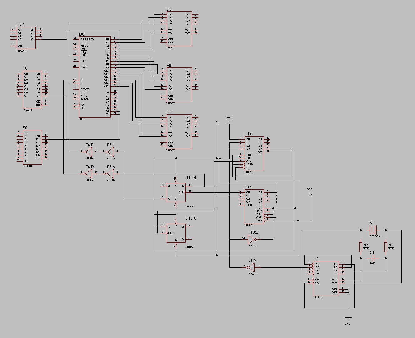
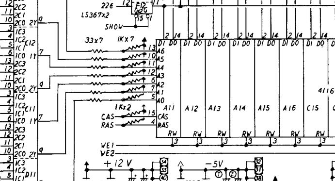
With nothing left to try I started making my own schematics up in the hope I could work out which RAM was responsible for the sprites.

Due to the complex nature of this board set, I was stuck for quite some time looking on the lower video PCB assuming (yes I know) that this is where the sprite RAM could be but was unable to find any problems at all.
Taking a step back I reversed the PAL chip XM_A-7D- into equations. Using these equations and the schematics I had drawn up I could take an educated guess as to what RAM chip was the sprite RAM.
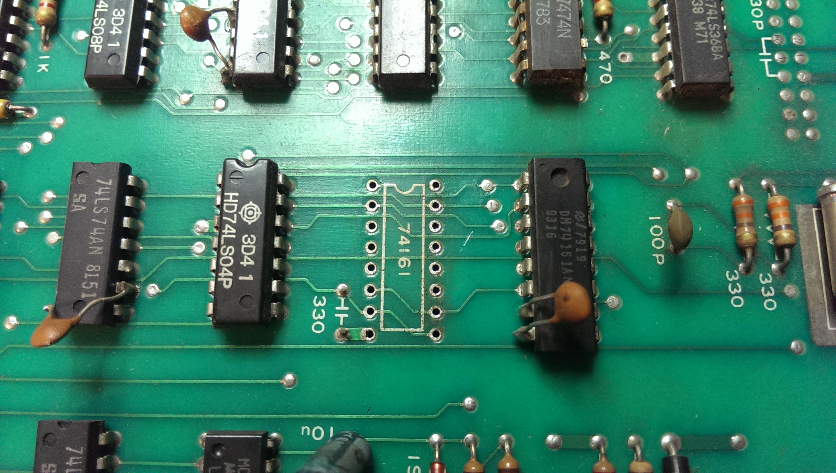
Knowing that the sprite RAM lies at address 0xc0000, this means that address pins A19 & A18 would need to be active. Looking at the equations I could see that output pin 17 of the PAL chip would fit this address so I followed the signal which led to the /CE line of a 74LS245 of IC40 on the top CPU PCB.
xm245

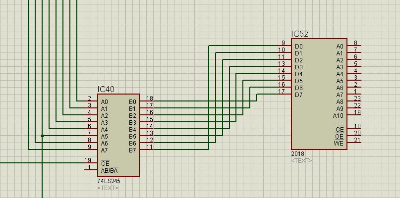
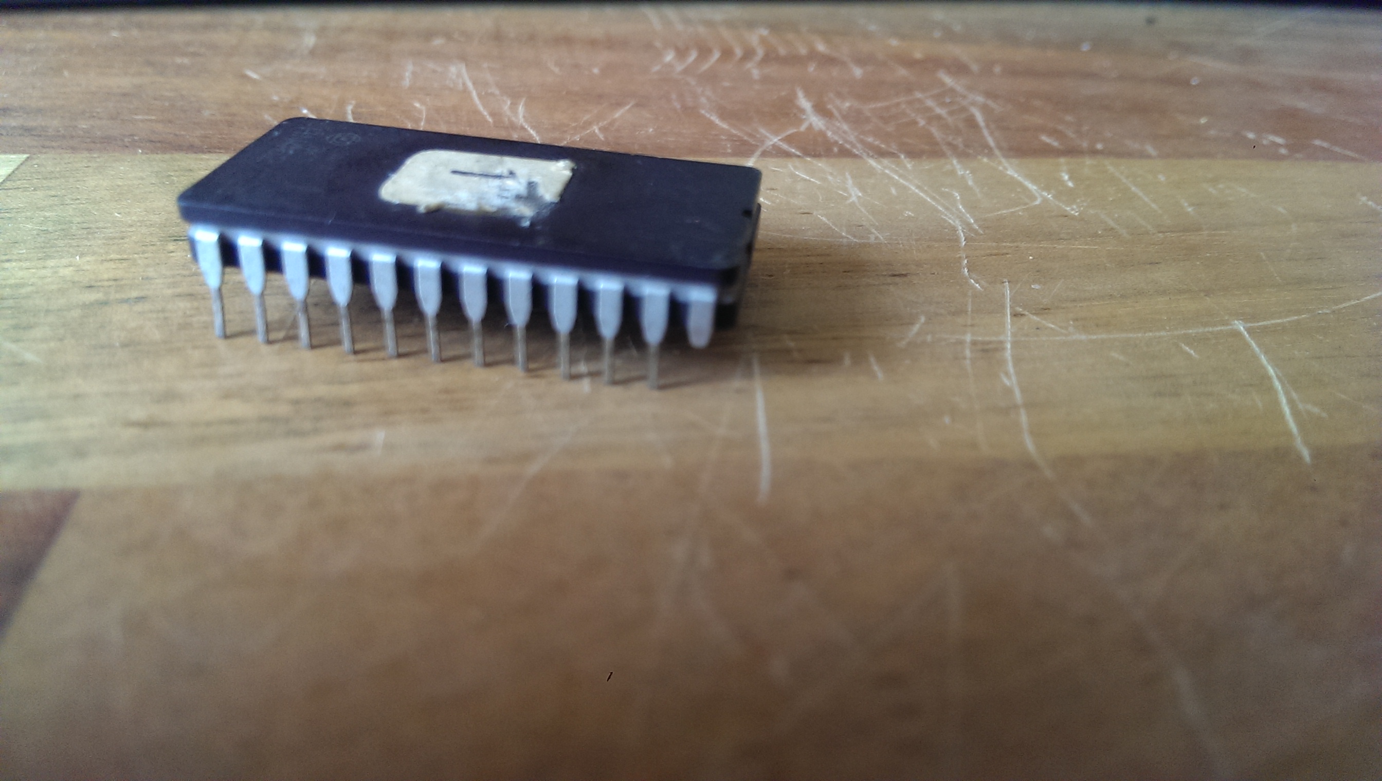
The only chip that this chip goes to is a 2018 RAM chip at location IC52.
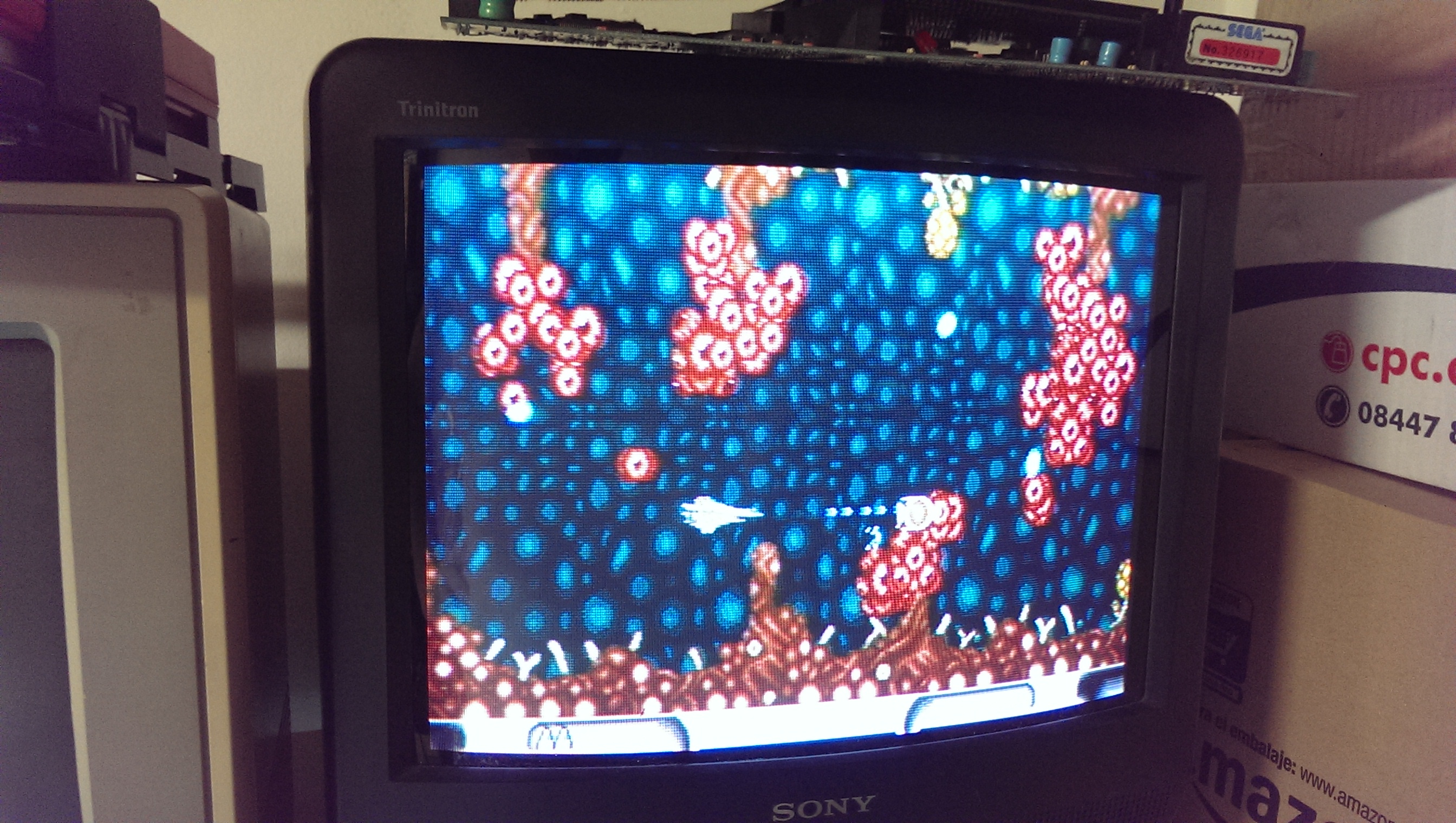
This was pretty good news. I removed the chip and it failed the tests so I replaced it and now all the POST tests pass.
The sprites are all back to how they should be too.
IMAG0733

Ill be keeping hold of this board I think. It was one of the first games I ever bought since getting into this hobby so it will stay with me for good now.

Konami GT repair log

 PCB Repair Logs, Repair Logs  Comments Off on Konami GT repair log
Jul 232014
 

A friend of mine sent me this really mint original Konami GT PCB saying it suffered from vertical stripes across most part of screen.

Konami_GT


Fired up the board and …he was right 🙂

Konami_GT_isue


Initial test said all RAMs were good so the problem was elsewhere.Without any schematics I started my visual inspection as usual.I noticed that the only IC replaced on this mint PCB was a 74LS157 @H13.Since a socket was installed, I removed this IC and all the part of graphics affected by stripes disappeared so I started to think problem was generated after this part of circuit.In particular I traced an output (pin 7) of this 74LS157 to pin 4 (RAS) of some TMM4164 DRAMs (there are 16 of them).Probing these DRAMs with my logic probe revelaed that on four of them pin 2 (DATA IN) was pulsing but the pin 14 (DATA OUT) was stuck high.So I desoldered (they were @G2, G3, H4, H5 position)  and test them in my Hi-Lo Systems ALL-07A programmer and the result was this:

TMM4164_testing

They all failed miserably.I was lucky since had  some good  4164 DRAMs taken from a scrap PCB in order to repair a Commodore 64 motherboard.Installed them and goodbye stripes for ever!Board 100% fixed.

Konami_GT_fixed

 Posted by at 10:18 pm

Juno First repair log #3

 PCB Repair Logs, Repair Logs  Comments Off on Juno First repair log #3
Jun 262014
 

Third repair log from the batch of Juno First boards.
On power up the board was completely dead. No clocks were present on the CPU or many other IC’s.
As this is a bootleg board the available schematics do not fully apply and the clock circuit is normally handled by custom chips so this was a bit of a learning experience.
To help in dealing with this problem I started making my own schematics up.
junobl

Using a logic probe I could see that the outputs of the 74LS161 @ H14 were all HIGH. As there is no clock present to this chip it should not have counted anything at this point and they should all be LOW. This meant to the board was booting up in an incorrect state and the clock circuit was never starting.
I desoldered and replaced the offending 161 chip.
IMAG0616

The clocks were now all present but I just got a static blue screen and the watchdog was constantly resetting the system.
Using my in circuit Arduino tester I knew the ROMs could all be read correctly by the CPU. I also knew all the program RAMs were fine.
Replacing the 6809 CPU allowed the game to boot properly.

Next problem was the sound or lack of it.
The sound CPU is a good old Z80 so I fitted the Fluke and did a ROM check. This reported back an incorrect signature and when I removed the ROM I see this
IMAG0618

The VCC pin was missing. I soldered a new pin onto this and this board is fully fixed.

The last bootleg board has been a major pain and at this point in time I have admitted defeat with it. I have also been harvesting parts from it to fix the others so it will be written off.

Fujitsu FM-TOWNS Marty PSU repair log

 Console Repair Logs, Repair Logs  Comments Off on Fujitsu FM-TOWNS Marty PSU repair log
Jun 172014
 

I got from a German customer this nice Fujitsu FM-TOWNS Marty console.

For the uninitiated FM-TOWNS Marty a Japanese console whose hardware is derived from its “big brother” FM-TOWNS computer.It has some of the coolest perfect arcade ports ever published like Splatterhouse, Bubble Bobble, The New Zealand Story, Tatsujin Oh and others.

As every Japanese device it has to be powered by 100V/110V so European people must use a step-down converter capable to reduce our 220V/240V to proper voltage .

This is what the owner of this console forgot to do by mistake..:)

So, after some seconds the “magic smoke” came out from the console.

Obviously the console did not power at all so i opened it and I immediately noticed some blown components.In particular the main 2A fuse was blown and a 100uF 200V capacitor was literally exploded on its top.The blown fuse was a good sign since it means he made his duty blocking the excessive current flowing in the circuit but the big 100uf 200V exploded capacitor meant  that this overcurrent reached also other components before the main fuse blown up.So, I decided to further investigate.Usually the first component after main fuse and filter capacitor is the bridge rectifier (which, indeed, rectifies the sinusoidal current in continuous one).In my case there was a 600V 1A bridge rectifier marked ‘S1WB S60’, here the datasheet:

S1WB Datasheet

Infact, as I suspected, I tested it with a multimeter and it was shorted.

So, I desoldered these three bad components:

and replaced them with equivalent ones:

Reassembled the console, powered it and got this:

Mission accomplished.

 Posted by at 8:08 pm

Juno First repair log #2

 PCB Repair Logs, Repair Logs  Comments Off on Juno First repair log #2
Jun 152014
 

So here is the second repair log.
Pretty simple this one but I never took any pictures of the actual fault so Ive taken a snapshot of the event in MAME to show it.

The game plays as normal but when the blue ball enemies spawn into the game the froze up on screen and did nothing as circled in red in the picture below.
juno2

On my visual inspection I noticed a 1K pull up resistor array next to the bank of 4116 RAM chips what cracked in half.
juno2-1

Replacing this fixed the fault.

I did initially think there was another fault as the ship movement in attract mode seemed a bit strange but after checking in MAME this is a characteristic of the non Gottlieb version. In the Gottlieb version this behavior is not present.