Double Dragon repair log #6

 PCB Repair Logs, Repair Logs  Comments Off on Double Dragon repair log #6
Dec 152014
 

Yes, yet another Double Dragon repair log..

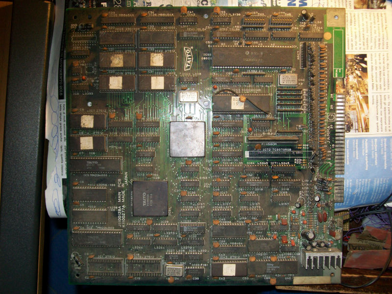
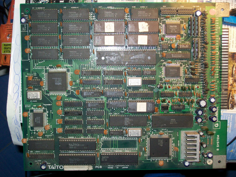
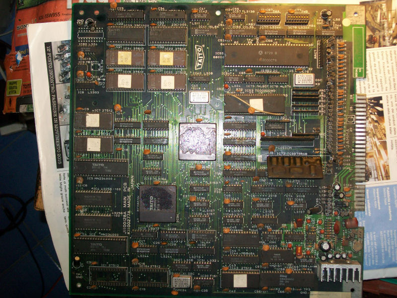
Found this PCB in the pile, honestly I can’t remember when and where I got it :

Double_Dragon_PCB

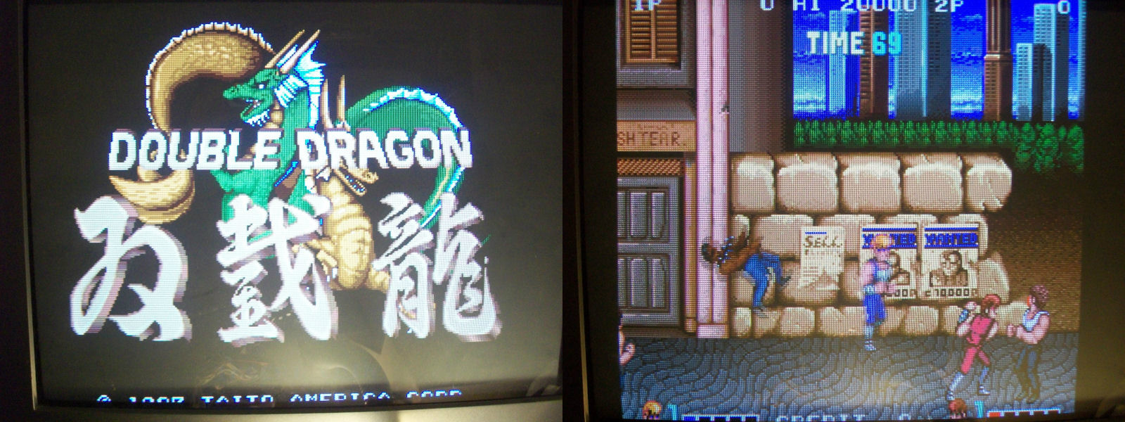
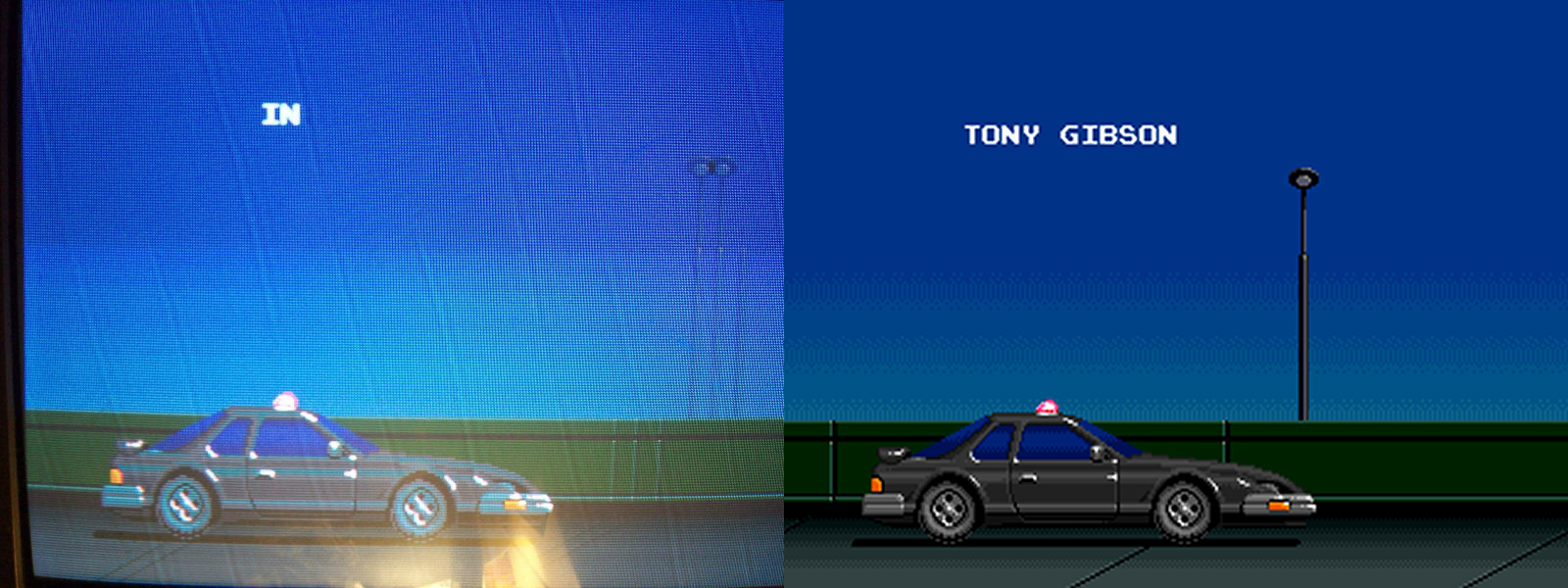
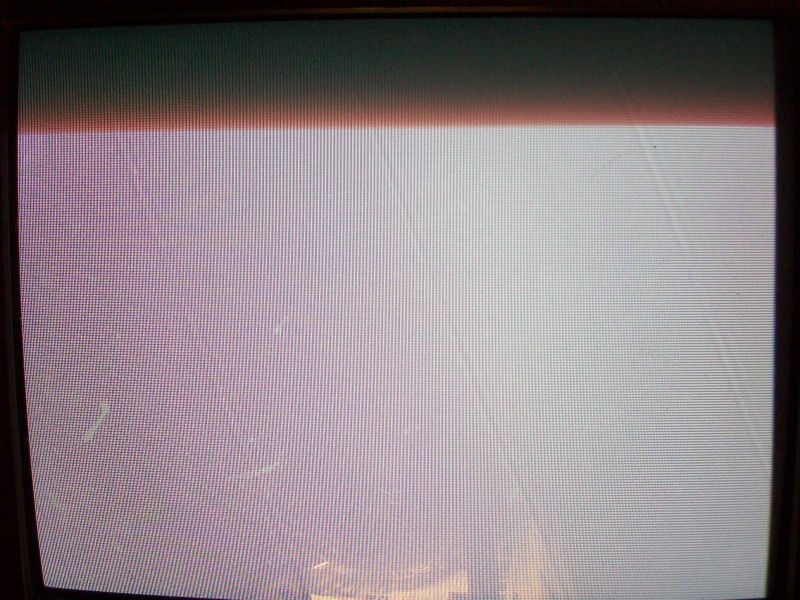
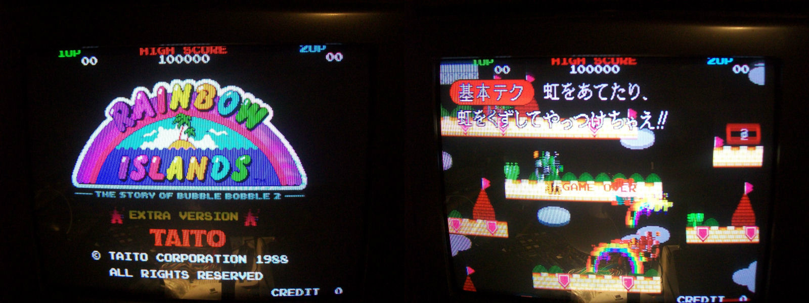
Once powered ON I was greeted by this title screen:

Double_Dragon_scrambled_screen(1)

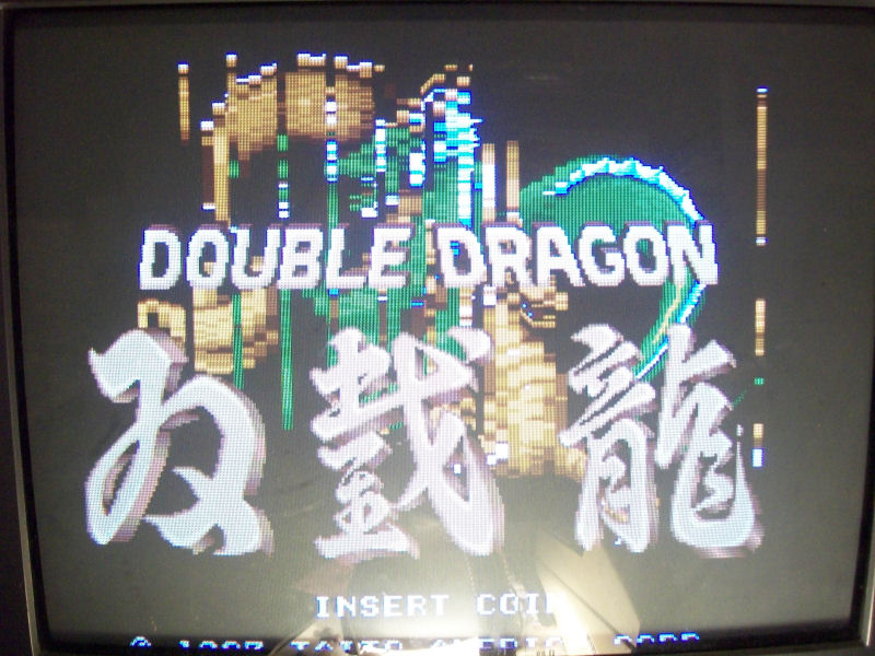
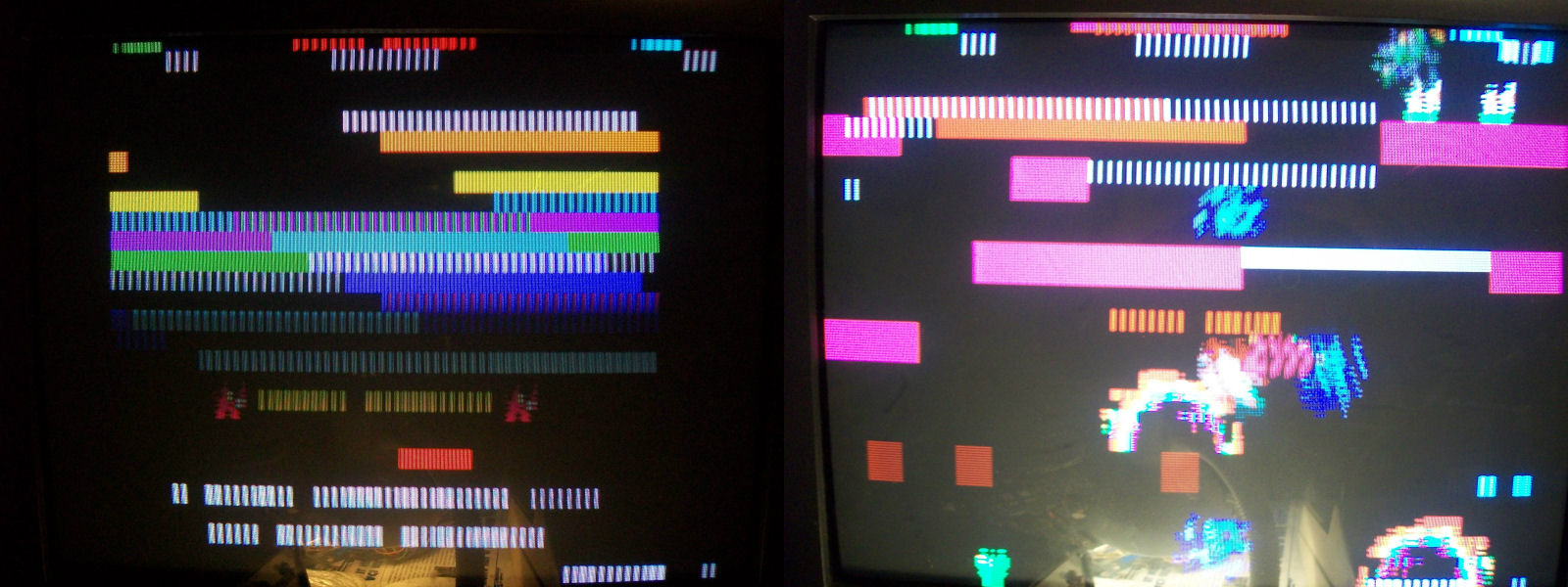
Also sprites in game were all blocky with some parts floating on the screen:

D_D_sprites

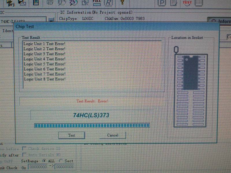
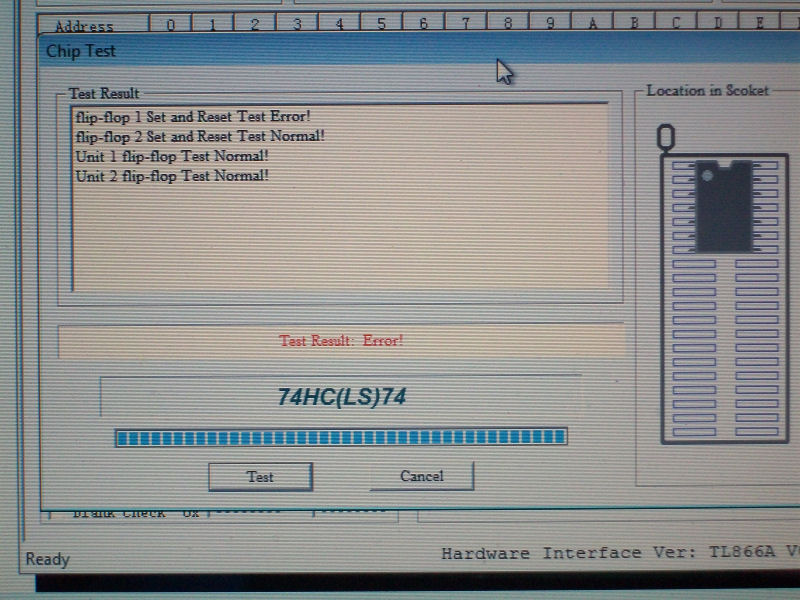
I also noticed that some sound FXs (especially speeches) were missing so I decided to first troubleshoot this issue.Probing one of the OKI MSM5205 @IC81 I found that all four data outputs were not toggling.The chip read data from the two samples EPROMs not directly but through two 74LS157 multiplexers.I found that select line (PIN1) of the one @IC96 was stuck HIGH so data inputs were not selected at all.I traced it back to an output  (PIN3) of the 74LS393 @IC62 so I desoldered it but it was good.Probing the its CLEAR pin I found that it was stuck HIGH.Tracing it back lead me to an output (PIN6) of a 74LS74 @IC75. I desoldered it and tested it out-of-circuit  having confirm that it was bad:

74LS74_testing

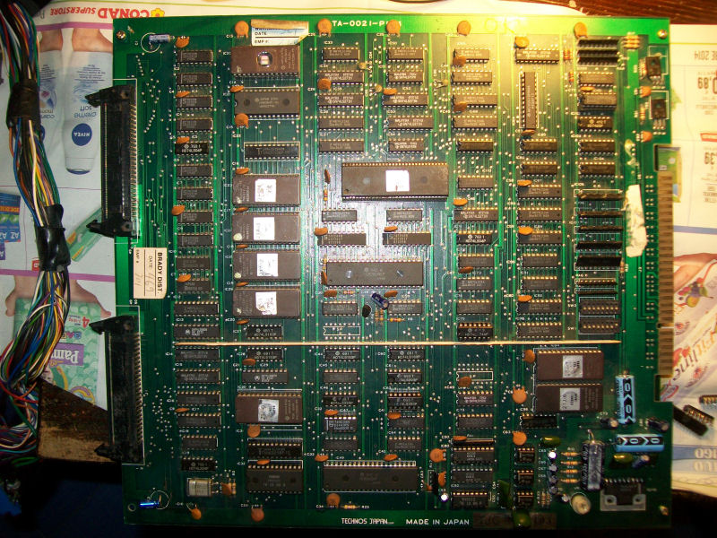
With sound FXs fully restored I decided to come back to the sprites issue.Fault was located in the VIDEO board since I swapped a good one and issue sprites came back normal.Luckily we have schematics so I started to check for parts of circuits involved in the sprite generation and handling but after two days of troubleshooting and a lot of suspected ICs replaced in vain I came to a dead end.I was nearly to give up and declare the board as not repairable but checking the last part of the object generation schematics I found a missing signal input (called ‘OCGL’) on PIN9 of a 74LS08 @IC36.This signal is generated by an output (PIN5) of a 74LS174 @IC69 always on VIDEO  board.

OCGL_signal(2)

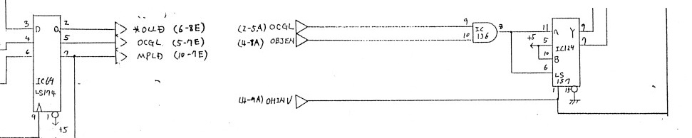
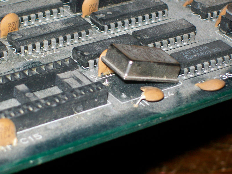
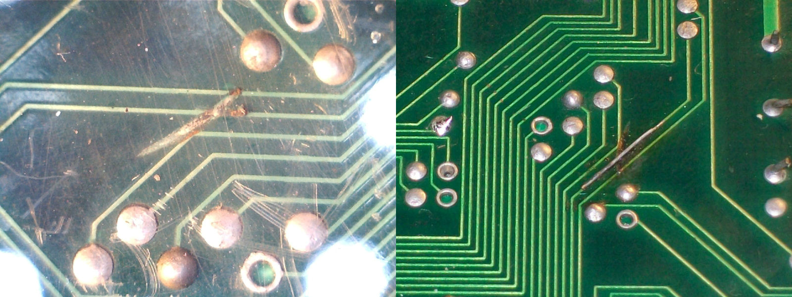
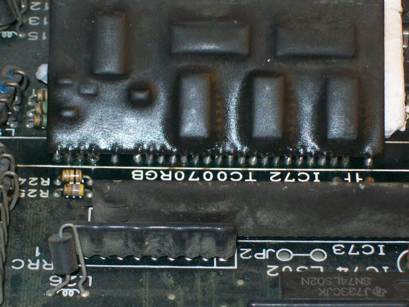
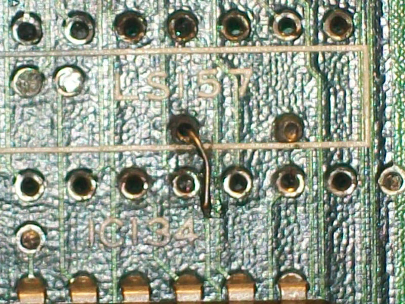
As I said this ‘OCGL’ signal was present as output of the 74LS174 but not as input of the 74LS08 so it was lost somewhere on the PCB.Following on solderside the traces between these two ICs I came across a via under a 74SL157 @IC34.I desoldered it and found this:

corroded pad

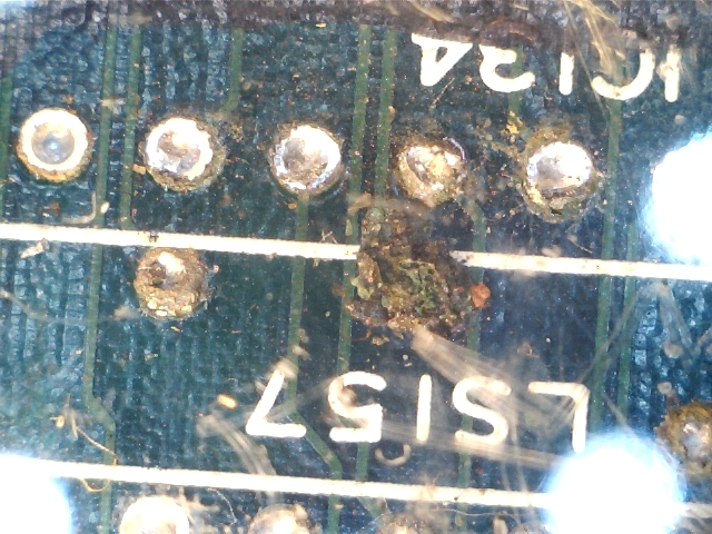
Oxid literally had corroded and eaten the pad and part of trace thus preventing the ‘OCGL’ signal reaching the input of the 74LS08.A tiny piece of AWG30 wire:

AWG30_fixed

and Billy e Jimmy Lee bros could fight again!

D_D_fixed_


 Posted by at 9:37 pm

Rainbow Islands repair log #4

 PCB Repair Logs, Repair Logs  Comments Off on Rainbow Islands repair log #4
Nov 272014
 

Another TAITO PCB on the bench.This time we have a Rainbow Islands one:

Rainbow_Islands_PCB

The first thing I noticed was (dust apart..) the lack of the TC0070RGB module.For the uninitiated this custom in SIL package is a DAC so it converts digital RGB output of the PCB into analog signals.I borrowed this custom from my Bonze Adventure PCB and installed the needed sockets as always.Once powered on the board, I was greeted by a solid black screen so I started investigating.Probing the main 68000 CPU I found there was no clock at all.Main clock is generated by a 16MHz oscillator @X1 and then divided by a near 74LS161 counter.I visually inspected this part of circuit and found this:

16MHz_oscillator

Replaced the oscillator gave me a fully working board but then it was time to find a proper replacement for the borrowed TC0070RGB.I knew this custom was reverse-engineered by Macro (thanks to him) some time ago:

https://www.arcades.plus.com/Taito-RGB.html

https://www.arcades.plus.com/Taito-RGB-Instructions.html

So I order a couple of bare PCBs and assembled one:

TC0070RGB

I can say it works like the original part, no differences at all, I higly recommnend this replacement.

 Posted by at 10:12 pm

Crime City repair log

 PCB Repair Logs, Repair Logs  Comments Off on Crime City repair log
Nov 172014
 

Another board donated from my arcade operators friends.It’s time for Crime City.

Crime_City_PCB

For the uninitiated, Crime City is a beat ’em up developed by TAITO that can be played by one or two players simultaneous.Here are the technical specs of the hardware:

  • Hardware – Taito System B Hardware
  • Board Number – K1100470A
  • Main CPU – 68000 (@ 12 Mhz), Z80 (@ 4 Mhz)
  • Sound – YM2610 (@ 8 Mhz)
  • Screen Orientation – Horizontal
  • Resolution – 320 x 224
  • Refresh Rate – 60 Hz
  • Palette Colors- 4096
  • Players – 2
  • Buttons – 2
  • Joystick – 8 way

The board booted fine but I immediately noticed that there was no sound at all except for some scratching noises.Besides, some colours were wrong and some characters tended to pink compared to the correct ones from MAME (see wheels of car in the picture below, MAME screenshot is on the right) :


colour_comparison_1

As usual I started my troubleshooting with a visual inspection of the PCB and found a broken track on the solderside which I promptly patched with some AWG30 wire:

broken_track_fixed

This fix restored correct colours (the broken track was actually connected to the TAITO ASIC TC0260DAR which is a custom pallette generator and this explained the reason of the fault)

As I said board was silent, no sound at all except for some noise sign that the main MB3735 amplifier was working fine.Digital audio section is made by a Z80 CPU which commands a sound synthesis YM2610 chip.With my logic probe I could verify that all was working fine there so fault was elsewhere.So I started to suspect the YM3016F sound DAC:

Y3016_F

Connecting its analog output to an external amplifier produced no sound (while digital input was present).This convinced me to replace it and so sound was fully restored .

 Posted by at 8:43 am
Nov 152014
 

First of all I want to thank JROK for providing me all the technical info and allowing its public release, without his help I would not have ever made.Let’s start with the story.

Some time ago a  friend of mine sent me his Splatterhouse PCB bought as working saying it got stuck upon boot  on ‘ROM TEST START!! PLEASE WAIT..’ message displayed upside down on a screen filled with red zero.So I started to investigate on the net and found that usually this kind of issues are caused by a faulty custom chip marked ’64A1′ @M4 on ROM board.This was confirmed by swapping this IC in another CPU board of Galaga88 with this missing component , in this case I got an ‘EEPROM ERROR’ message which is a further proof of the fault.

Thanks always to JROK we know that this ’64A1′ custom IC is nothing else than a HD63701 MCU with the exception of two custom opcodes not present in original part.You can go deeper into technical reading here:

https://www.jrok.com/hardware/cus60/cus60_an_owners_guide.html

So, programming a blank HD63701 MCU with the available dump from MAME won’t work due the presence of these two custom opcodes.So, patching a ROM is needed.

In the specific you have to change three bytes in the ROM  “VOICE0” at a specific offset.For example :  in Splatterhouse the offset is $FA8B and the new HEX values are “20 01 56”.

The string to search for in HEX is  “B7 C0 00 6E 00” and the first 3 bytes must be changed to  “20 01 56”

The patch seems to be needed at offset $FA8B for most games, but not all. Here’s a reference table :

Tank Force – $FA29
Blazer – $FA8B
Dragon Spirit – $FA8B
Galaga 88 – $FA8B
Marchen Maze – $FA8B
Splatterhouse -$ FA8B
Rompers – $FA8B
Blast Off – $FA8B
World Court – $FA8B
World Stadium (and WS ’89, WS ’90) – $FA8B
Bakutotsu Kijuutei (Baraduke 2) – $FA8B
Beraboh Man – $FA4E
Dangerous Seed – $FA8B
Face Off – $FA29
Pisto Daimyo no Bouken – $FA8B
Puzzle Club – no voice ROM !
Quester – $FA1B
Souko Ban Deluxe / Boxy Boy – $FA8B
Yokai Douchuuki (Shadowland) – $FA8B

So, it was only matter to find some real blank HD63701.My first attempt failed since I bought as new some ICs that they turned out to be already programmed and, since they were the plastic HD637B01VOP one-time-progfammable version, they were unusable for my purpose.But then I was luck and found some HD63701VOC UV erasable ones:

HD63701VOC

So, it was only matter to program one of these MCU with MAME dump using my Hi-Lo Systems ALL-11C EPROM programmer and, at the same time, replace the ROM ‘VOICE0’ with the properly patched one.Once done, I had confirmation of what the good JROK said about. Operation  ‘NAMCO custom 64A1 replacement’ accomplished.

 Posted by at 7:14 pm

Rainbow Islands repair log #3

 PCB Repair Logs, Repair Logs  Comments Off on Rainbow Islands repair log #3
Nov 122014
 

First of all I wanna thank the people who donated me this (and other) PCB : “mille grazie” to Mr. Giuseppe (a long-standing arcade operator of my town) and his nice daughters Elena and Antonella!

Now, let’s begin with the log.

When I got  this PCB in my hands, I immediately tought it was a Rainbow Islands one:

Rainbow_Islands_Extra

But I was wrong, it actually was the Extra version (different ROMs and C-Chip).Before start the troubleshooting, I resoldered a wonky TC0070RGB module:

TC0070RGB_resoldered

Once powered on, I got a solid white screen with a clicking sound indicating that the watchdog circuit was active:

Rainbow_no_boot

There was clearly some trouble in main code execution so I started to test with my logic probe the two WORK RAMs  and I found some data lines stuck HIGH on the 6264 SRAM @IC25.I desoldered the chip and out-of-circuit test confirmed it as bad:

6264_testing

With a new RAM the board succesfully booted but graphics (tiles and sprites) were all blocky:

rainbow_blocky_GFX


This board (and other Taito ones on similar hardware ) uses two custom chips  in PGA package which generates sprites (the one marked ‘PC0900J’) and tiles (the ‘PC080SN’).They respectively address GFX ROMs through a couple of  74LS373 latches.Probing the 74LS373 @IC29 I found that all the outputs were absent.So I piggybacked a good one and tiles were restored but sprites were always blocky:

fixed_tiles


So, I went through the 74LS373 @IC18 and found it had output PIN19 stucked LOW while its input was toggling.Piggybacked this and also sprites were restored.Desoldered the two 74LS373 and they were indeed bad:

74LS373_testing

Replacing them both back this game to its former glory!


 Posted by at 9:09 pm