G.I. Joe repair log #1

 PCB Repair Logs, Repair Logs  Comments Off on G.I. Joe repair log #1
Oct 262014
 

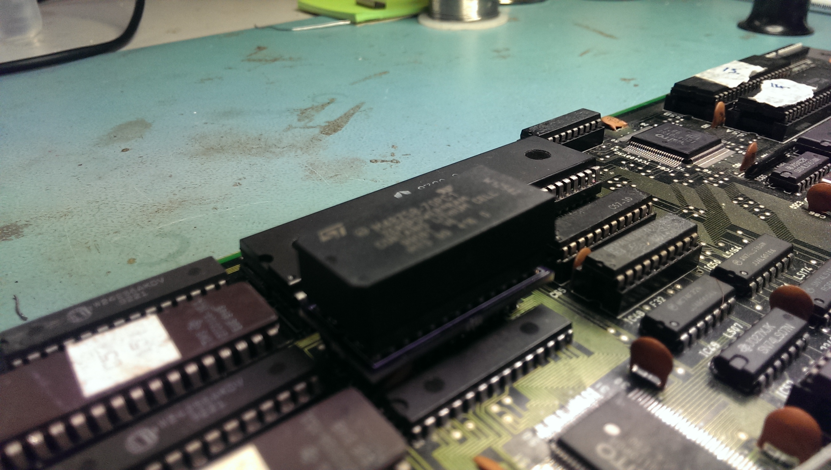
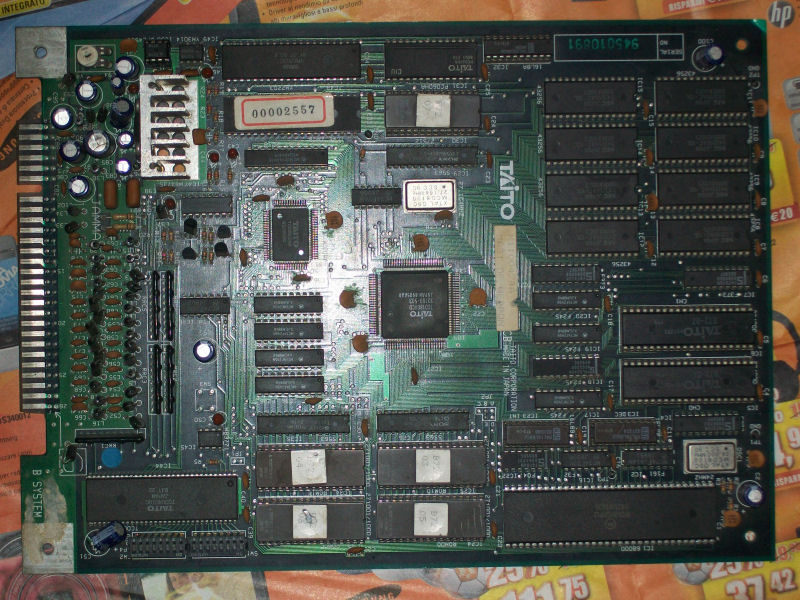
Got this original Konami G.I. Joe PCB from Ebay as not working.Looking at the auction picture I could see the ‘051550’ SIL custom broken in half, this was confirmed once I received the board:

G.I._Joe

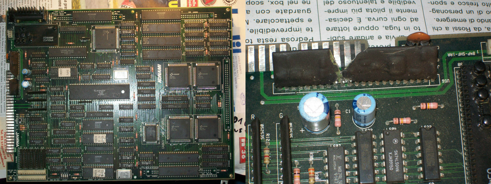
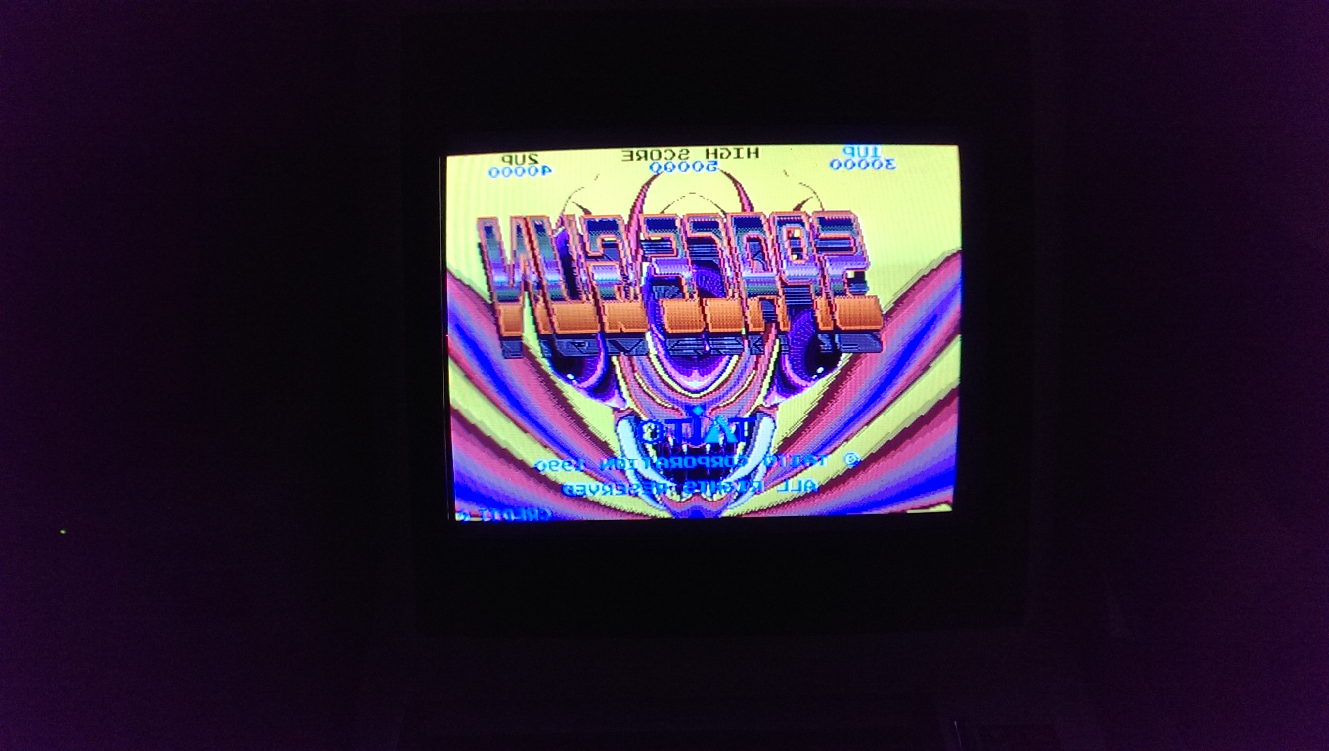
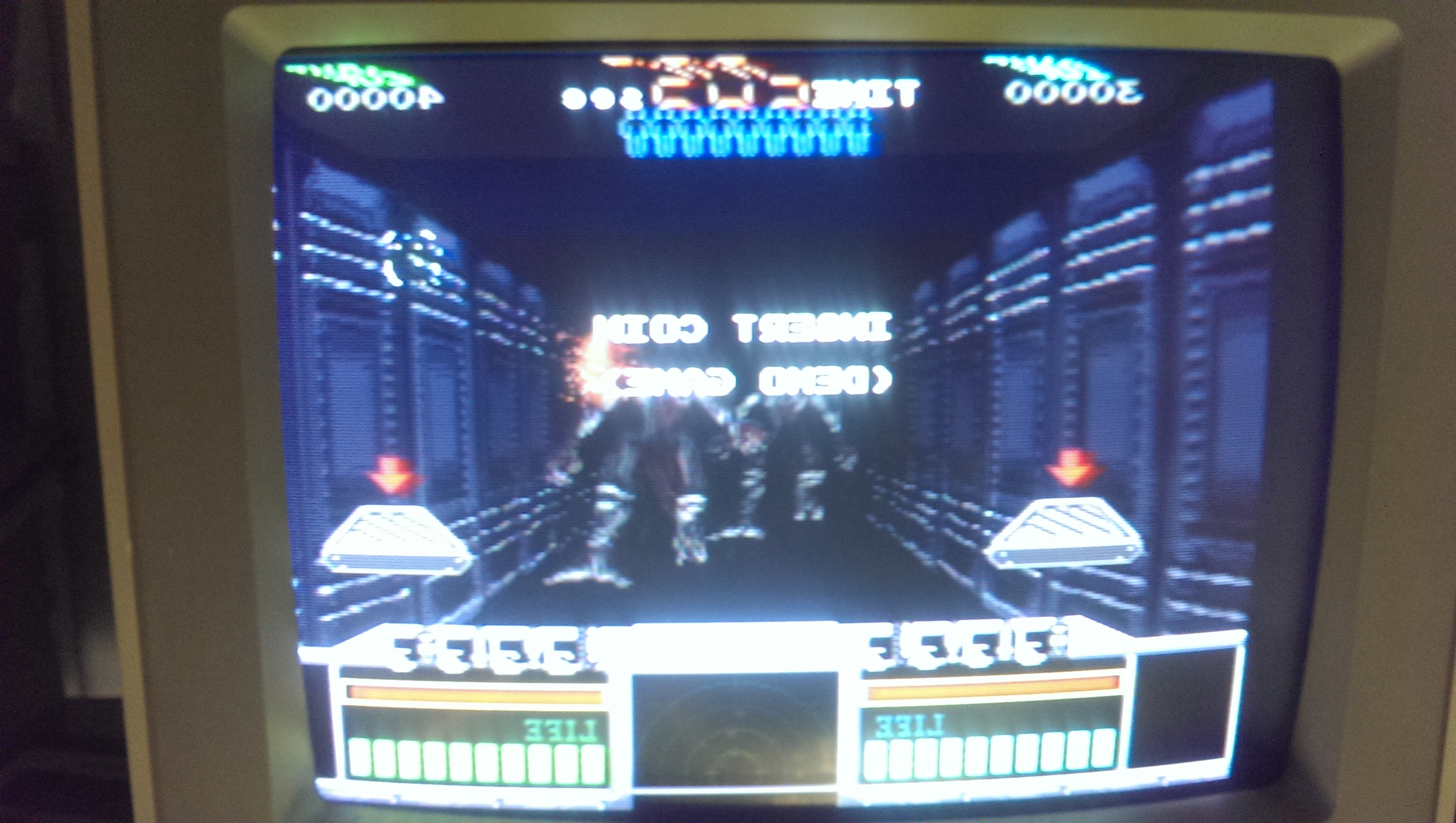
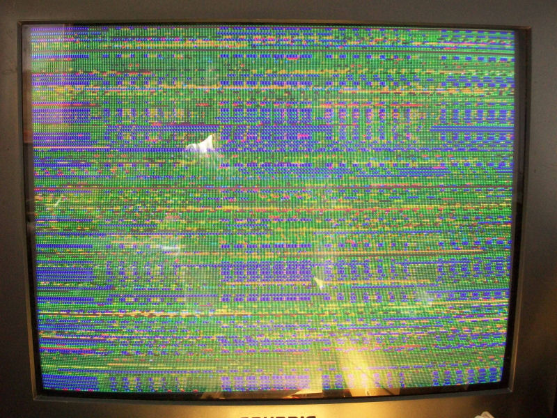
For the uninitiated, this custom is of vital importance since it generates the master RESET for the whole board, infact 68000 CPU RESET line was stucked LOW and I got only a static screen:

J.I. Joe_no_RESET

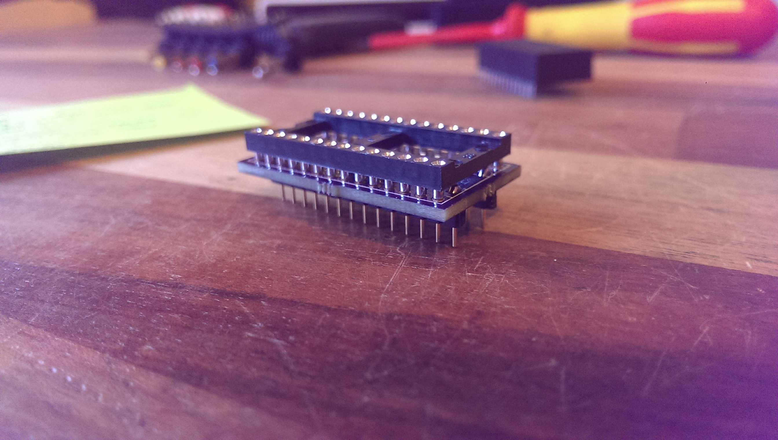
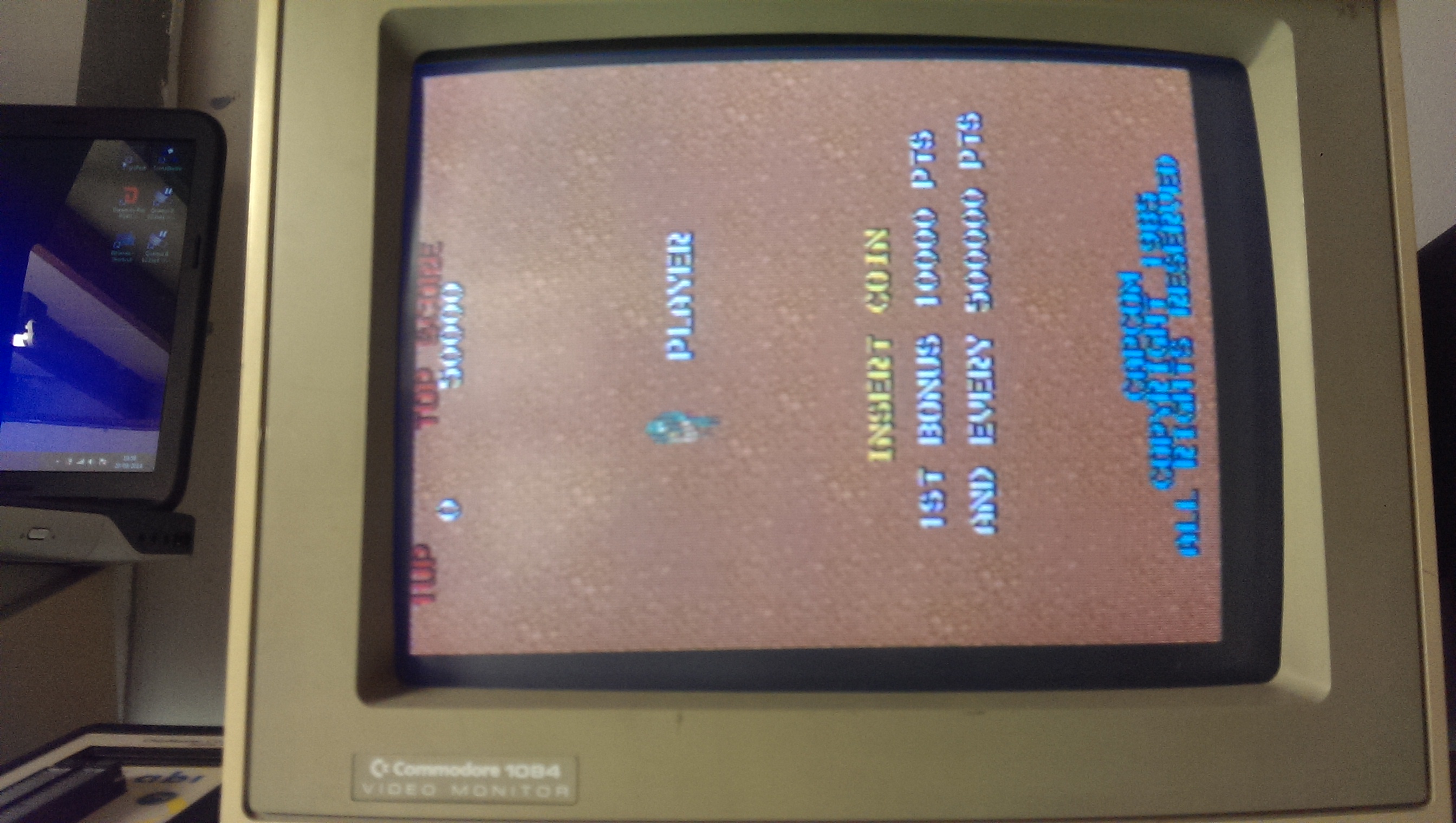
I had many Konami faulty boards for spare so I took this custom from one of them and, after replaced it, the board resetted properly but with an error on VRAM @16K:

VRAM_error

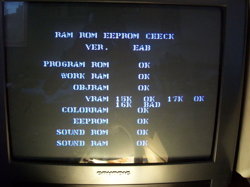
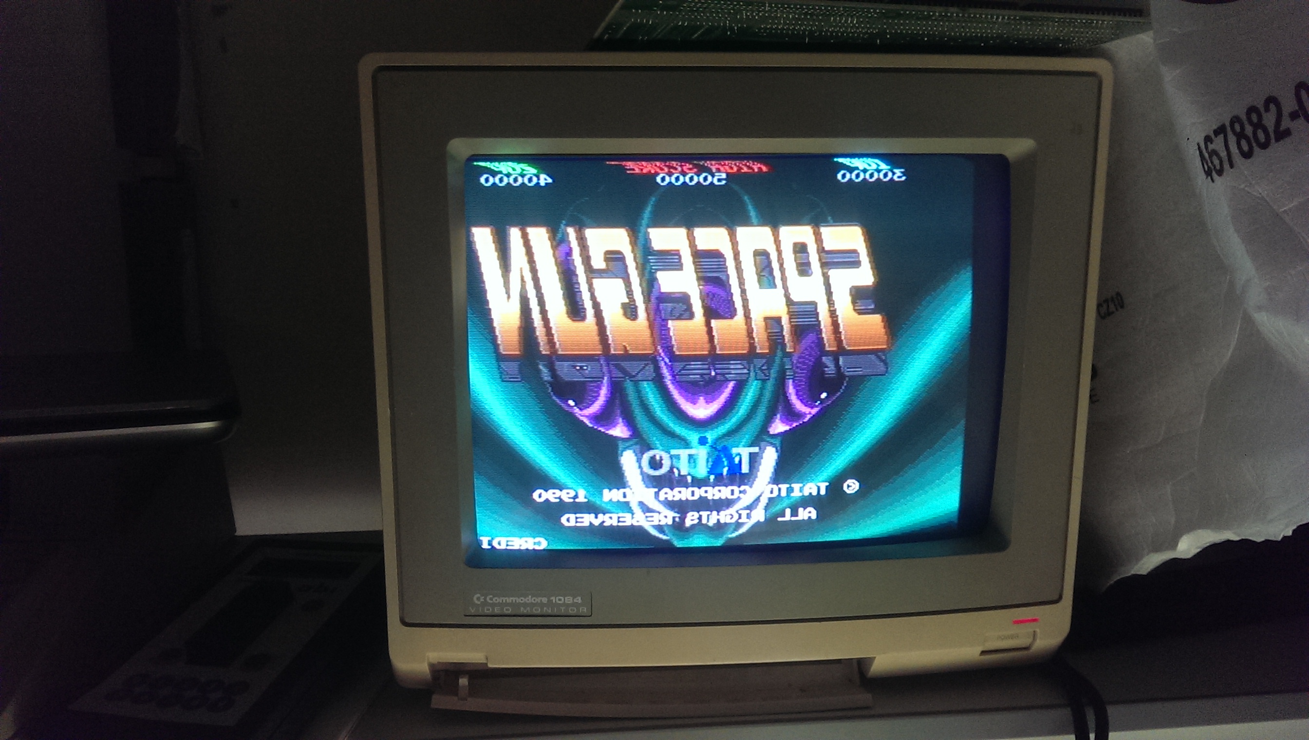
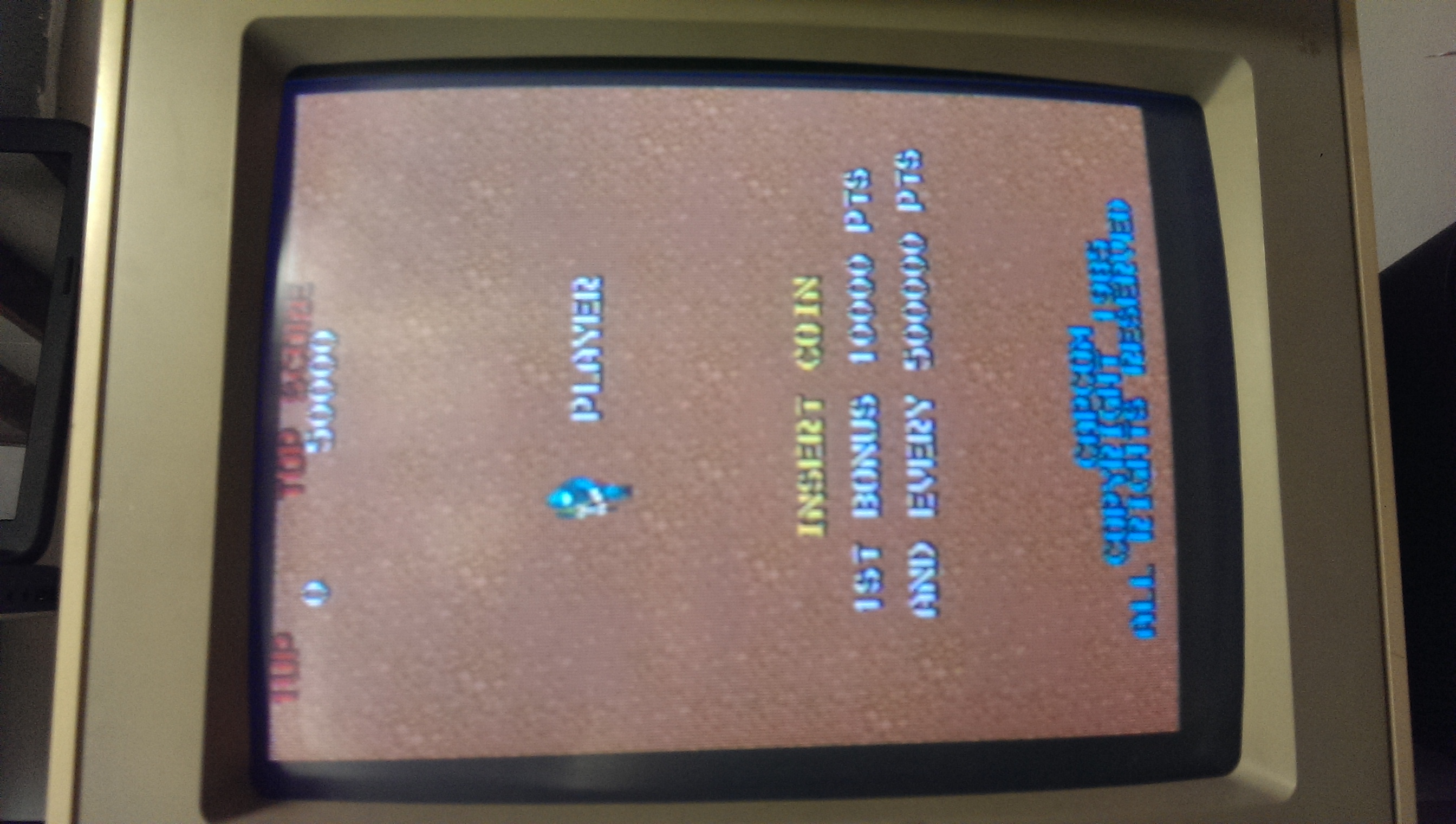
Desoldered and test the 6264 RAM out-of-circuit confirmed it as bad.With a new RAM game was fully playable  (also with sound which is quite rare as this board uses the ‘054986A’ hybrid custom module) but something was wrong :

wrong_colours


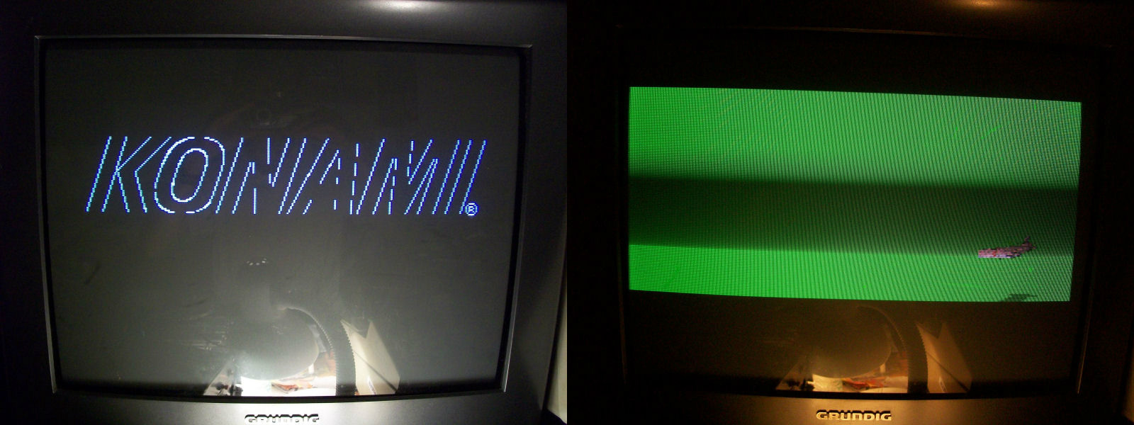
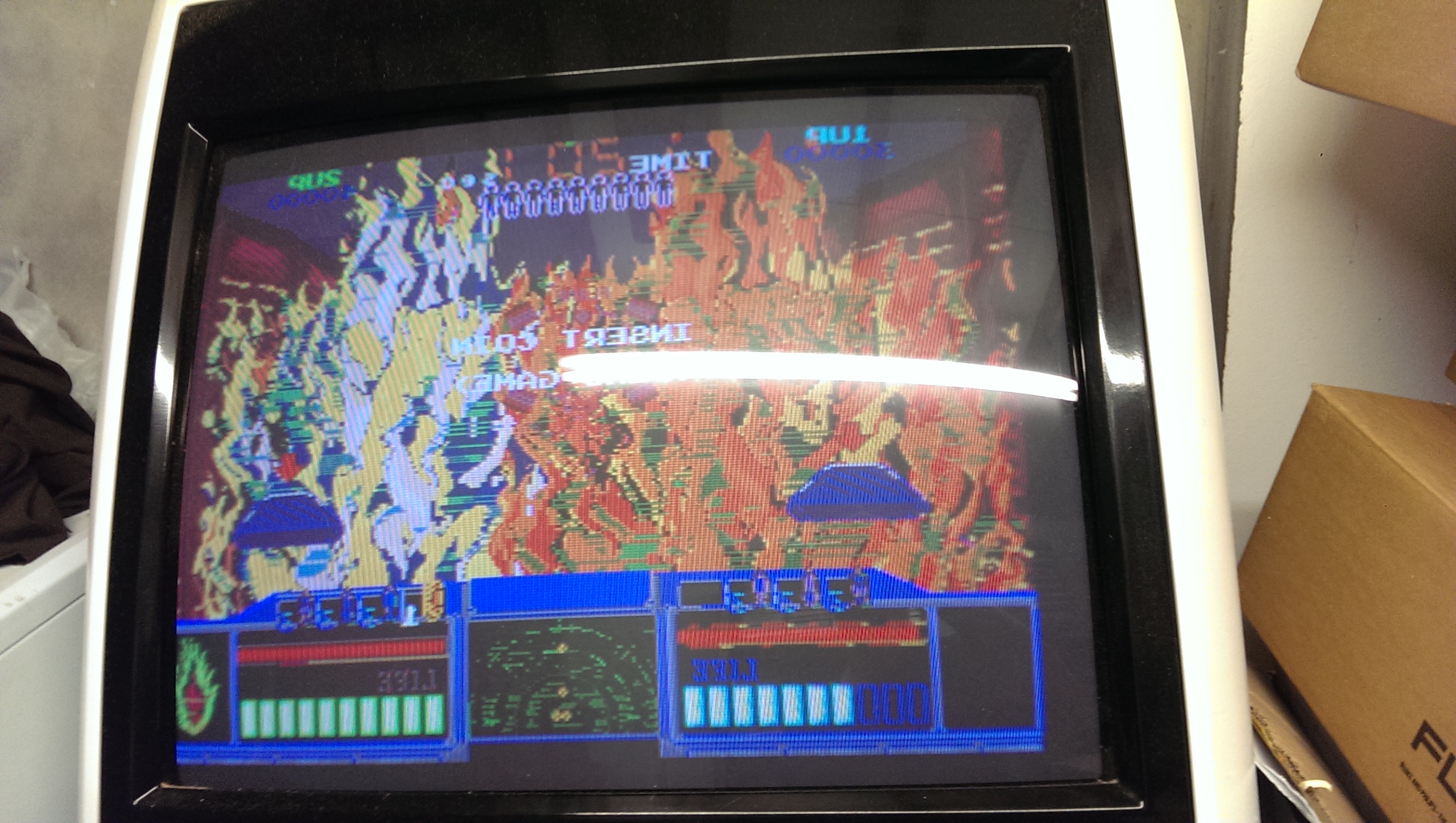
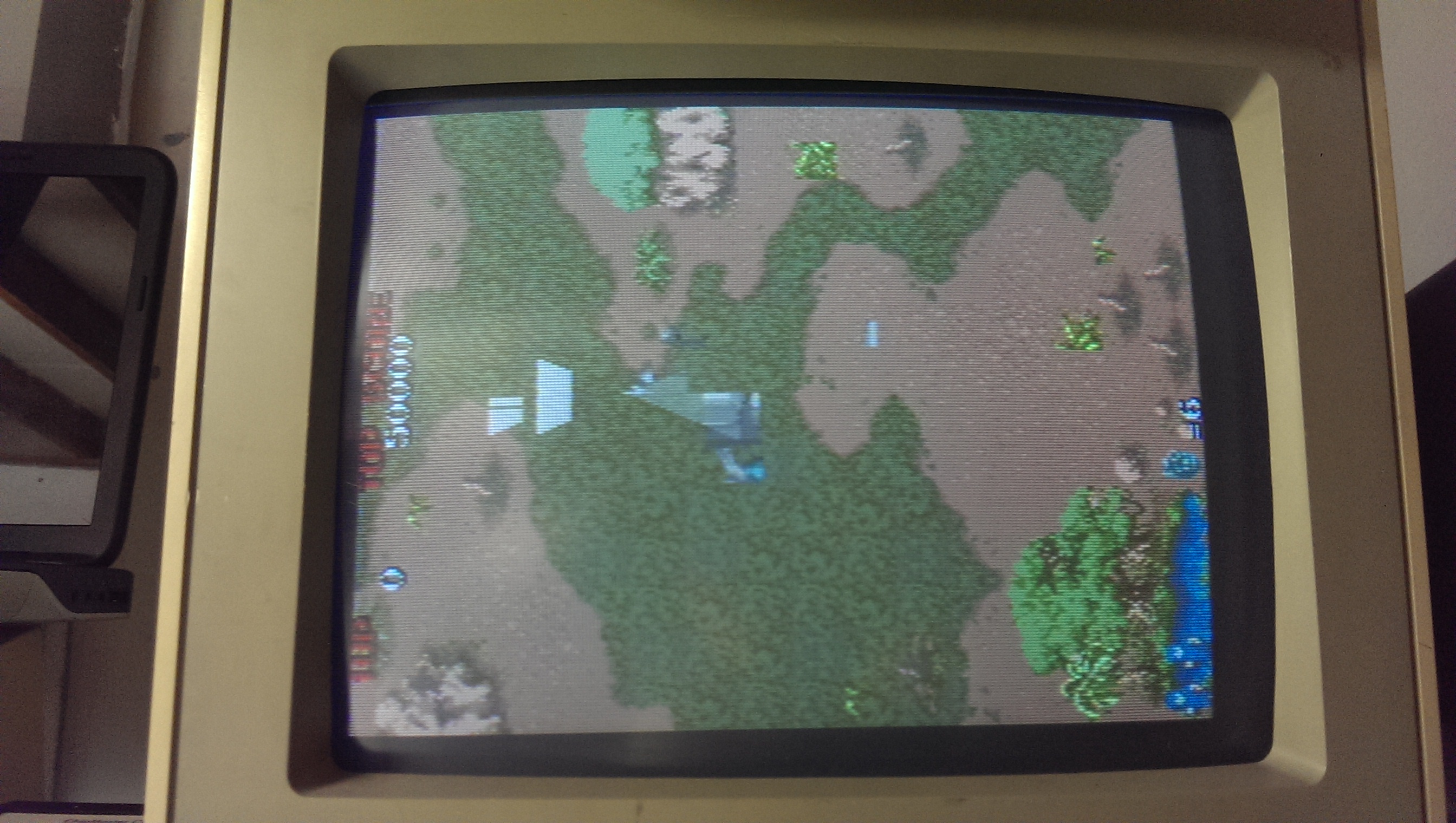
like some colours were missing from certain backgrounds and this was confirmed also by the color check I ran in TEST MODE comparing the output with the one from a working board:


palette_comparison

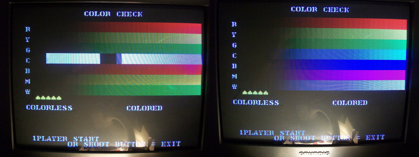
Color RAM was OK as reported by initial test so I start to suspect the ‘053251’ ASIC since I had a similar fault on a Bell & Whitles PCB.According to MAME this ASIC is a palette/priority chip :

053251_ASIC

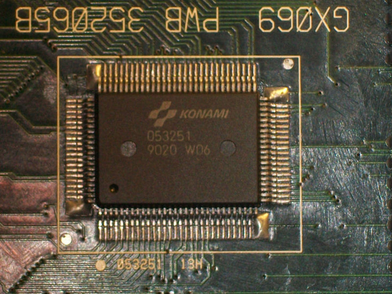
So this convinced me to replace it.And I was right since colours came back to normality:

colours_fixed

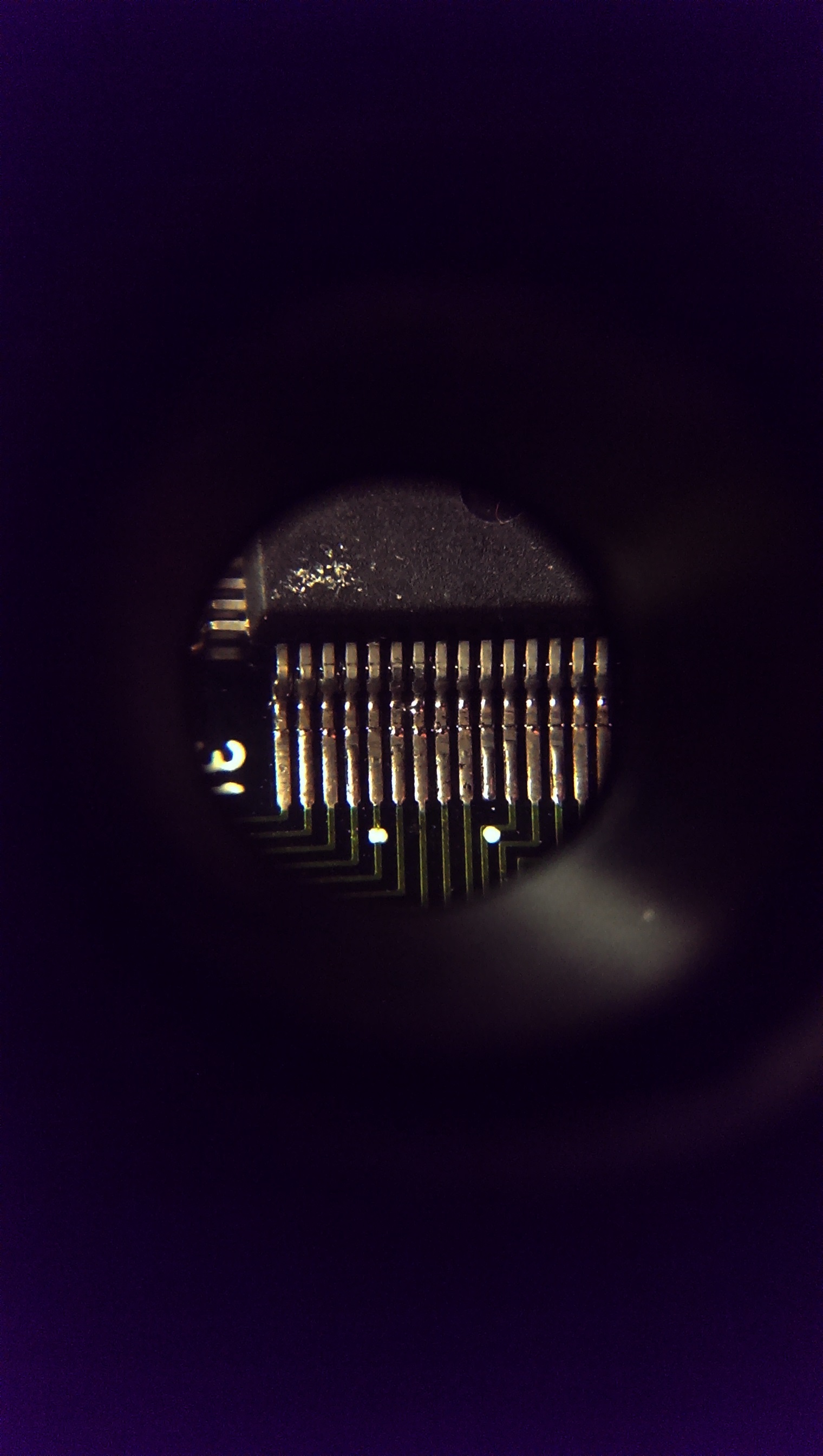
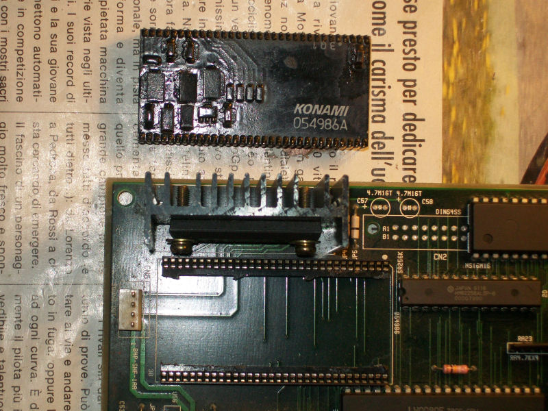
Gameplay was fine now but some of the sound FXs were muffled and distorted.It could not be due the ‘054986A’ hybrid module since the issue was limited only to some FXs so I started to check the audio circuit (commanded by the usual Z80 CPU).When I piggybacked the 6116 SRAM @6C all the sound FXs were restored so I desoldered the chip in order to test it out-of-circuit:

6161_bad


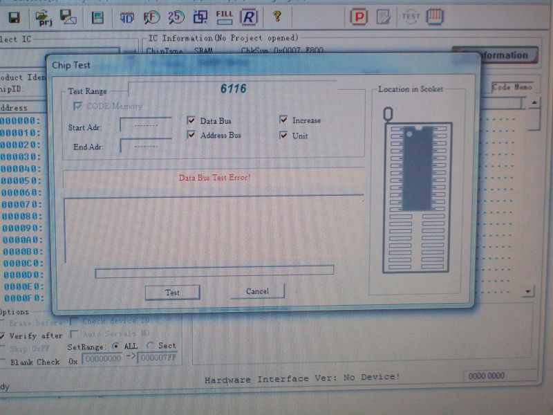
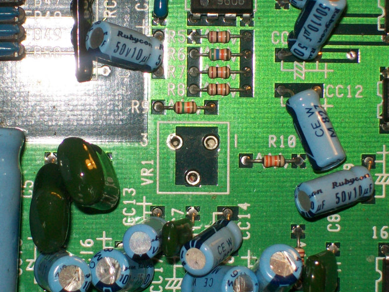
RAM was really bad though this fault was not reported by initial RAM/ROM test.Not satisfied, finally, to top it all I recapped (with tantalum capacitors) and socketed the ‘054986A’  sound hybrid module’:

054986A_recapped&socketed

End of job.

 Posted by at 6:59 pm

CPS1 A-BOARD (new revision) repair log

 PCB Repair Logs, Repair Logs  Comments Off on CPS1 A-BOARD (new revision) repair log
Oct 242014
 

Contradicting the current tendency to sell all the CPS1 stuff due its extreme unreliability (my mate Porchy knows something about…) I decided to buy a faulty CPS1 motherboard (also know as  ‘A-BOARD’).Seller claimed board was good except for the audio completely missing.

When the board arrived (it was actually a ‘CPS DASH’ so the last revision with 12MHz oscillator), I immediately noticed it was missing the volume pot:

missing_2.2KOhm_pot


So, I took this pot (2.2KOhm to be exact) from a dead CPS1 motherboard sure that this was the cause of the missing audio.But I was wrong since still I got no audio.Touching with fingers the solderside pins of the HA13001 main amplifier gave me some noise from speakers so fault was elsewhere.

First I started to test Z80 audio CPU with my logic probe and no activity was present on data/address lines.I knew from other CPS1 repair logs that bad Z80 CPU is a very common fault on this boards so I decided to replace (using a round machine-tooled socket) it without thinking twice.

Z80_replaced


And this was enough to restore full sound back.


 Posted by at 11:11 pm
Oct 022014
 

To start with this game wouldn’t boot at all.
The board has had one of its big surface mount custom chips replaced in the past and apart from one lifted track that has been patched out, the swap was very neat.
First job was to desolder the sub CPU and fit the Fluke to see what was going on.
I found a broken link between the ROMs and D4 of the CPU. I patched this and did a ROM check.

The ROM address space lies between 0x0-0x3ffff.
The Fluke 9010 signature for this is 8A4F

This was correct but the game still refused to boot.
Checked the RAM. This lies between addresses 0x20C000-0x20FFFF
Both of these failed and both were replaced.
Ram checks now pass but the game still does not boot.

Next I tested the shared RAM.
This lies between 0x210000-0x21FFFF
This passed up until address 0x21FFFE where I couldn’t write to the address at all.
I haven’t figured out why but I’m starting to think this is normal as the code writes to this address space separately but never reads from it. Maybe some kind of watchdog reset or something?

As the game still did not boot I opted to desolder the main CPU and fit the Fluke there.
Found another broken track between the main CPU and one of the ROM’s (I forgot which one as this repair has taken ages).
I patched this out and the game now boots but there is a faint output on screen. Further probing with the scope revealed a dead TC0070 RGB custom chip.
I replaced this and now got a booting game but with wrong colours.
IMAG0883

IMAG0885

This had me stumped for a while as there are a lot of custom chips on this board and any one of them could be a suspect as they all feed into and out of each other.
I opted for a different approach to normal and made up a small converter PCB that let me use 0.6″ chips in place of 0.3″ chips. This allowed me to use an NVRAM chip in place of the palette RAM.
IMAG0948

IMAG0933
So with this in place I let the game boot to the title screen and powered off. With the contents stored in the NVRAM I was able to dump it and repeat the operation for the second palette RAM and interleave the dumps together. No I had this I could compare it to what MAME has at the same point. This allowed me to see if the data being written was actually correct or not.

Here is what I got on my first attempt and what I should have got.
SGwrong
SGright

As you can hopefully see, bits 4 and 6 are wrong here so I took a closer look at the custom chip TC0110PCR that feeds the RAM chips.
IMAG0934

There was the smallest bridge of solder across D6 and D7. Removing this gave me the colours back.
IMAG0944

IMAG0945

Everything else appears to be working so I am glad this is now sorted.

Sep 212014
 

Another one of Ben’s boards.
Had the usual graphics issues you normally get associated with those four 2114 RAM’s only this time the RAM’s had already been replaced and all four were good.
IMAG0908

Following the inputs and outputs from these RAM chips I found some broken traces, probably a result of desoldering them originally.
Pin 1 of the RAM at location 3H was not connected to anything. I patched this and it fixed the solider sprite on the title screen but some in-game graphics were all messed up.
IMAG0909

IMAG0910

After confirming all other connections were good I noticed two other 2114 RAM chips that had been worked one and socketed so I checked those too.
Initially I found pins 3 and 4 of the RAM chip at 1B. Patching these gave me this result
IMAG0912

Getting there but not quite.
A little further inspecting these chips and I also found pin 15 of the same chip not connected to GND like it should be.
Patching this one gave me a perfectly working game.
IMAG0913

IMAG0914

Master of Weapon repair log

 PCB Repair Logs, Repair Logs  Comments Off on Master of Weapon repair log
Sep 112014
 

Got this PCB as usual from Ebay as faulty, seller said it was missing some sounds.PCB was in a clean state:

Master_of_Weapon_PCB

Once powered up, actually, all sound FXs were present but music was missing at all.Sound hardware is formed by a Z80 CPU which controls a YM2203 FM synthesis IC coupled with a YM3014B DAC and all sound (music+ FX) are pre-amplified by a NEC uPC4556C OP-AMP before going to  the main MB3735 amplifier.Connecting the analog output (pin2) of the YM3014B to an external amplifier I could hear the music, this was still present on the OP-AMP input (pin5) but not on the output (pin7).So, I desoldered it and tested it in my chinese tester which reported it as good.But this did not convince me so I replaced it with an equivalent Mitsubishi M5218 and this was the winning move since music was fully restored.

End of job, see you next repair!

 Posted by at 10:39 pm