May 122016
 

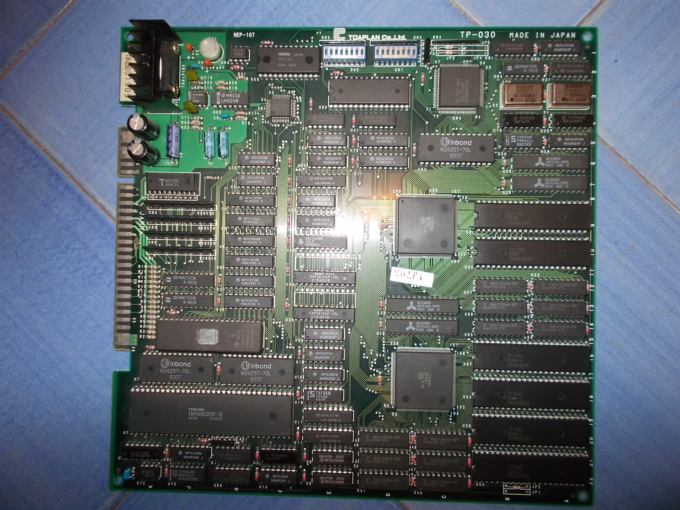
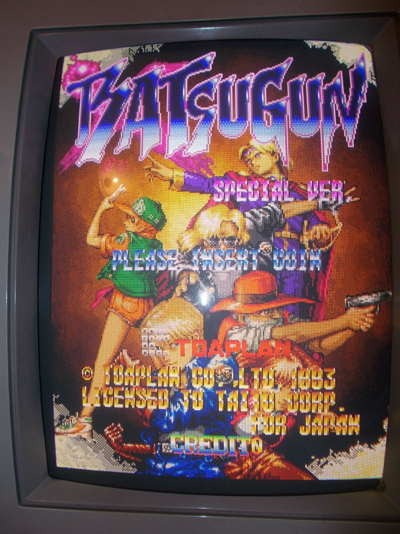
Received this Batsugun Special Ver. PCB for a repair:

Batsugun_Special_ver_Japan_PCB

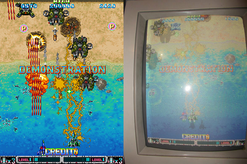
Game played fine but colors were all dull and washed-out, take a look at this comparison with a MAME snapshot on the left:

colors_comparison

or this video:

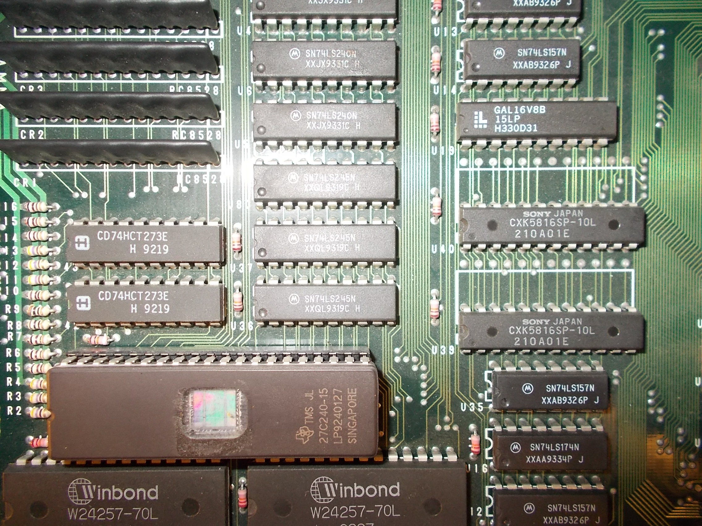
This was a clear sign of some troubles in colors palette circuitry.After studying the hardware, I was able to locate this section by shortcircuting some address/data lines of two CXK5816 SRAMs @U39 and U40 and at the same time observing  color changes on screen:

palette_circutry

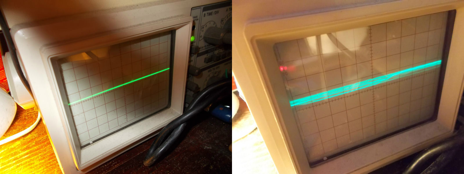
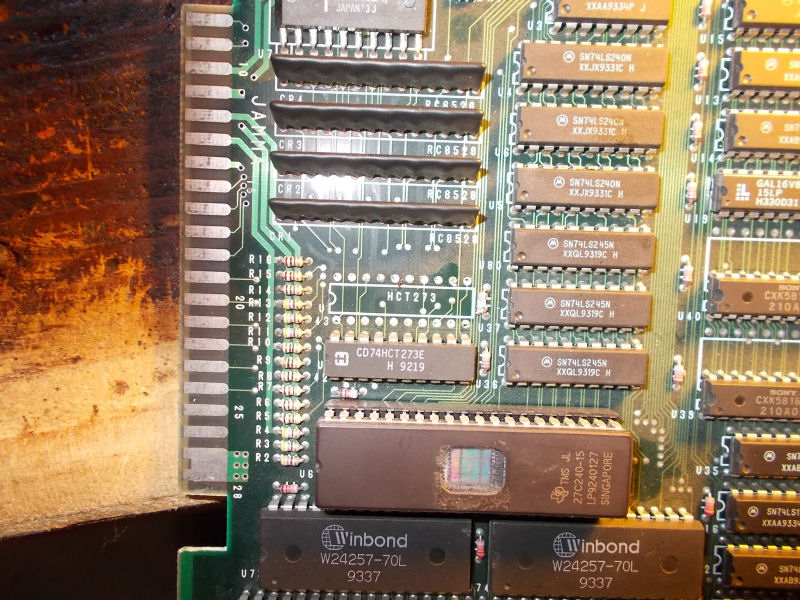
Besides the two mentioned SRAMs, you can see some 74LS245 and two 74HC273 involved in data bus (the first ones in exchanging data from/to the two RAMs, the latter in latching).When  I went to probe the two 74HC273 I found that input pin 13 of the one @U43 was stuck low  and its corresponding output pin 12 showed only weak signals:

74HC274@U43_probing

So confident I went to remove it:

74HC274@U43_removed

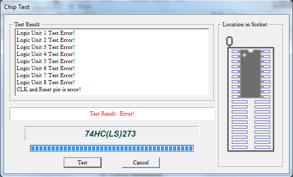
When I tested it out-of-circuit it failed:

74HC273@U43_failed

Once fitted a good IC and powered up again the board, the game played great with no further issues.

fixed

End of job.

 Posted by at 11:27 pm
May 072016
 

There are not only PALs on our beloved PCBs but also bipolar PROMs!

A bipolar ROM or briefly BPROM (“BIPOLAR” stands for the transistor technology used in the manufacturing process) is a OTP memory device, which can be programmed just once and hence the data programmed can never be erased.They were used for various tasks: address decoding, state machines, and video colour palettes, for example.Like every electronic part they can fail and nowadays obtaining a blank device is really hard and expensive.And even if you find it, your EPROM programmer  probably doesn’t support BPROMs as they are obsolete parts.

Someone replace them with EPROMs mounted in a custom adapter but we chose GAL devices as replacement since most of times there is no need of adaptation (if you program them in the right way, obviously).Besides, GAL devices are really common and inexpensive.Last but not the least, they can have fast access times like BPROMs require.So,today we open a new archive for GAL replacements of bipolar PROMs, you can find it under the menu ‘PLD Archive’ on main page.I hope you will enjoy it and contribute to its growth.


 Posted by at 11:20 pm
Apr 252016
 

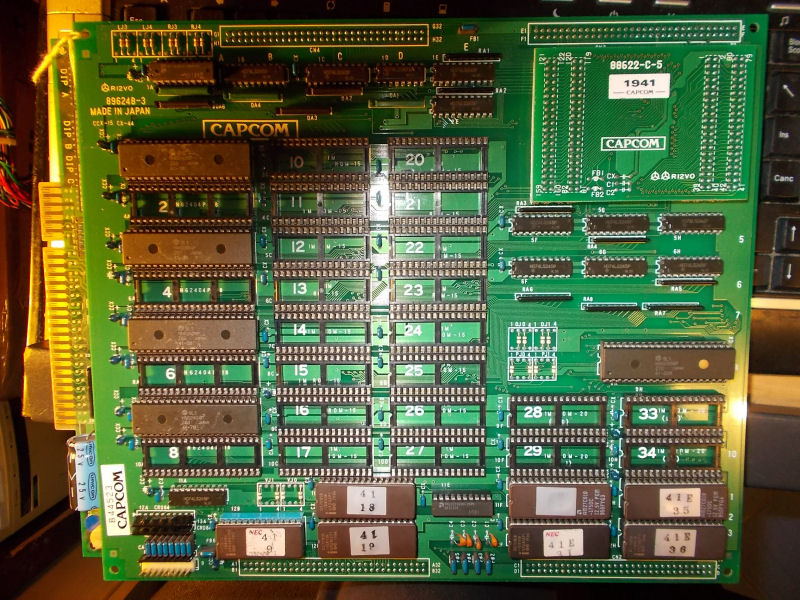
I had on the bench this mint 1941 : Counter Attack CPS1 boardset:

1941_Counter_Attack_PCB

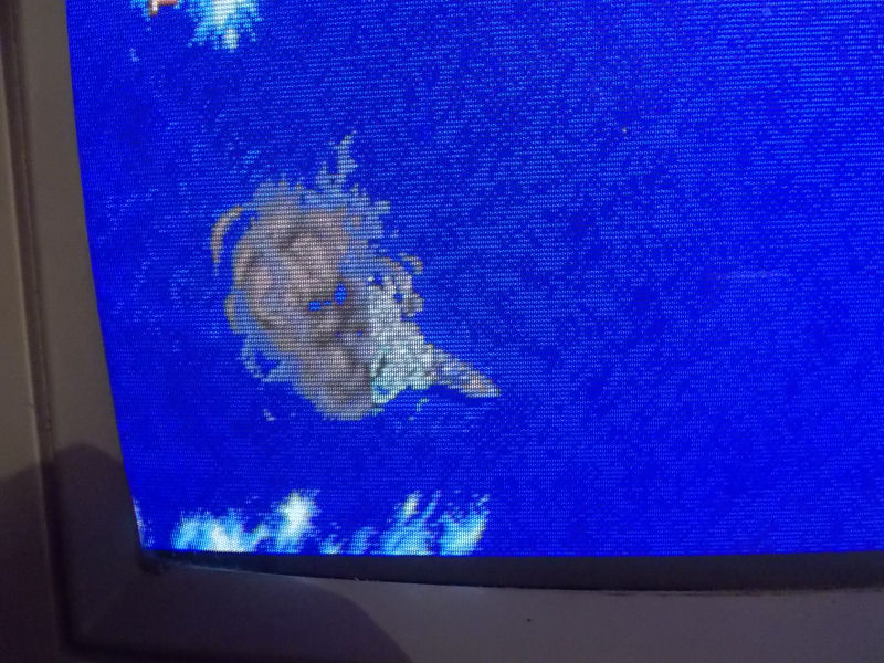
Board played fine except for a minor sprite issue on some objects on backgrounds which manifested only on first level:

sprite_issue

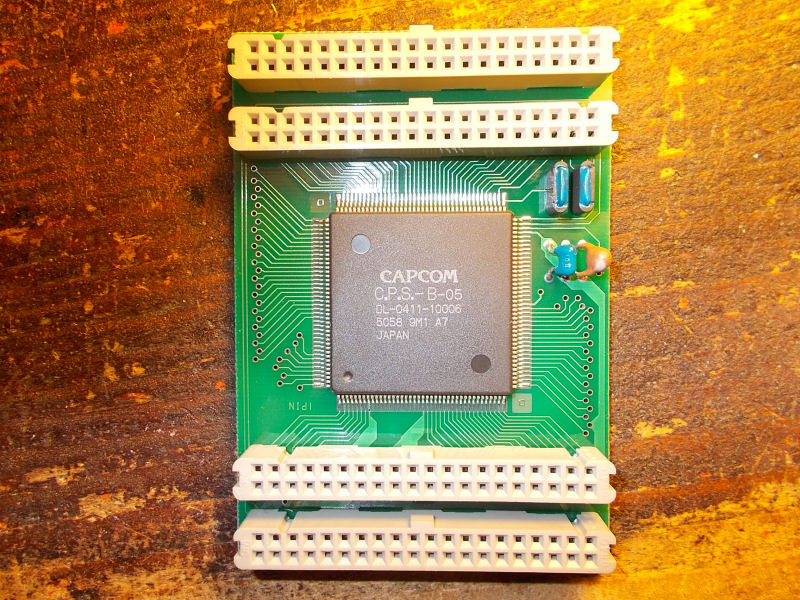
The game use the ‘CPS-B-05’ ASIC on C-BOARD which acts as a GPU generating all the graphics:

CPS-B-05_C-BOARD

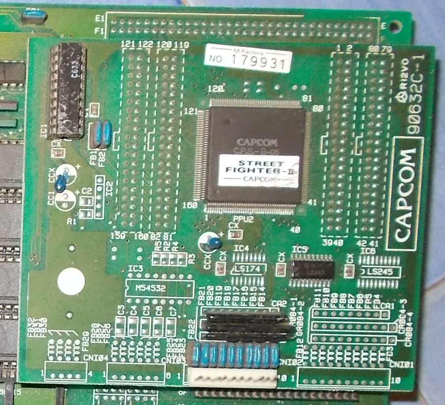
so I swapped a good known one from a Street Fighter II : The World Warrior boardset:

CPS-B-05_C-BOARD_SFII

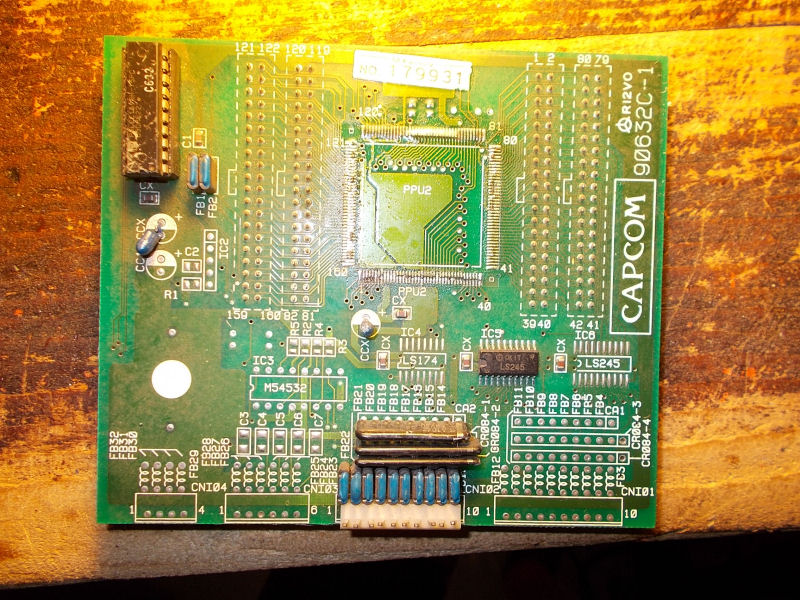
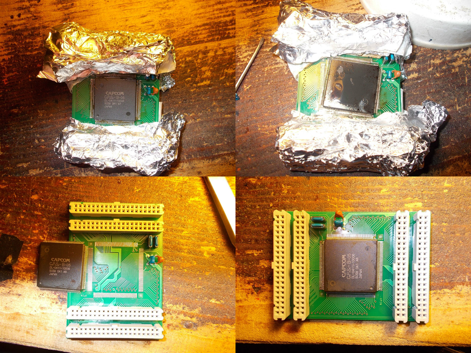
All the sprites were restored so I had confirm the ‘CPS-B-05’ ASIC was bad (probably an address line was ‘spitting out’ wrong address).I could swap the entire C-BOARD but appearances count too so I decided to transplant only the IC on the original C-BOARD.

CPS-B-05_SF2_removed

I used an hot-air rework station covering the plastic connectors with tin foil as protection against heat:

CPS-B-05_reworking

To solder the chip I used the ‘drag soldering’ technique:

I succesfully tested the reworked C-BOARD and declared board as 100% working :


 Posted by at 6:51 pm

Super Qix repair log

 General, PCB Repair Logs  Comments Off on Super Qix repair log
Apr 052016
 

Got this game for a repair.

The pcb was missing one program rom and a graphic rom.

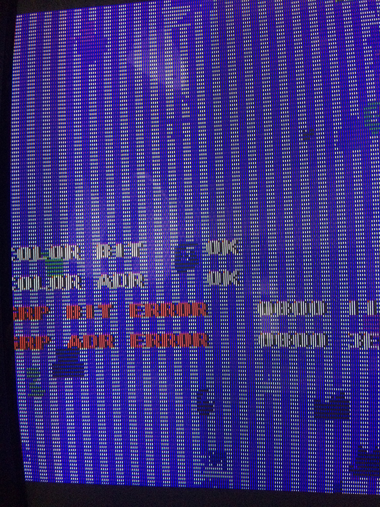
After checking which version was the game, I burned the correct eproms and I got this screen:

sqix1


A ram was reported bad but I didn’t know which one.

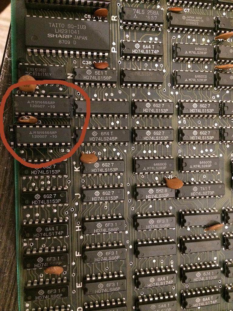
There were 2x 6116 SRAMS and 6x DRAMS type 4464.

When the error message is shown, the game get stuck in a loop and continuously checks the status, therefore I discovered that shorting pins of the DRAM @9L and 9M changed the hexadecimal value of the error.

With a logic probe the signals were oscillating but I decided to desolder them and put some sockets and test other drams I had to see if the problem changed or better could be solved.

Please note that all the DRAMS I had were taken from dead boards and I had no way to test them out of circuit.

So I proceeded to place the sockets and installed some drams chip and I got always different bits until finally it passed the POST test!

sqix2


Turned out that I had several defective DRAMS chips and I took the chance to use Super Qix as a DRAM tester 🙂

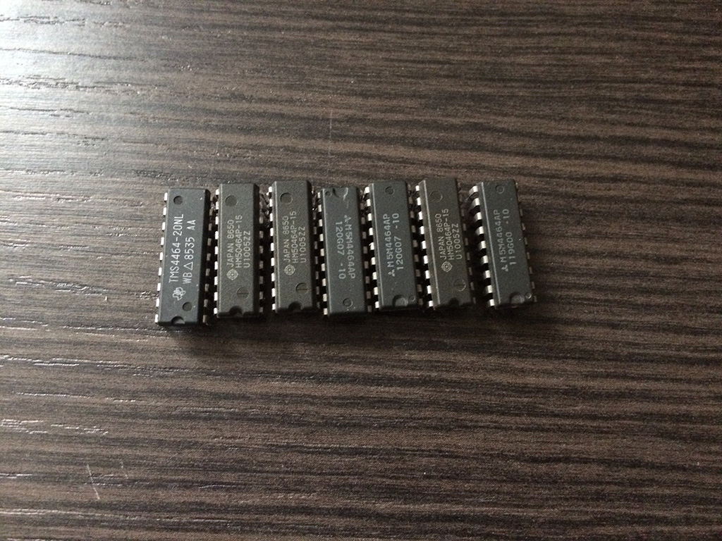
Below are a collection of defective DRAMS, as you can see they are all from different brands…

sqix4


Back to Super Qix, , after changing the DRAMS, the game passed all the tests without further errors but I got this:

sqix3


The game had still the gfx messed heavily even if the ram test was reported good.

I shorted two pins of DRAMS @6S and 6R and I could see some better picture beneath the mess, so I decided to change also those two drams

I started the game board without them in place and I got this:

sqix5


It was a good sign but to be 100% sure there were faulty I placed them back on the sockets @9L and 9M and I got again the error on the post screen!

After placing two good drams I got this:

sqix7


Decided to go straight to the next two drams @5P and 5M and replaced without any further thoughts and…..

sqix8


Problem 100% fixed! Game had no further problems

So turned out that the game had all the 6 drams faulty but the game checks only 2 Drams out of 6x.

The other checks are done on the color sram and program sram.

sqix6

Reading Irem MASKROM’s

 General, Technical Info  Comments Off on Reading Irem MASKROM’s
Apr 022016
 

I got an M92 PCB here that uses MASKROM’s from SHARP.
These MASK’s in particular are pin compatible for either 27C020, 27C040 or 27C080 EPROM’s.
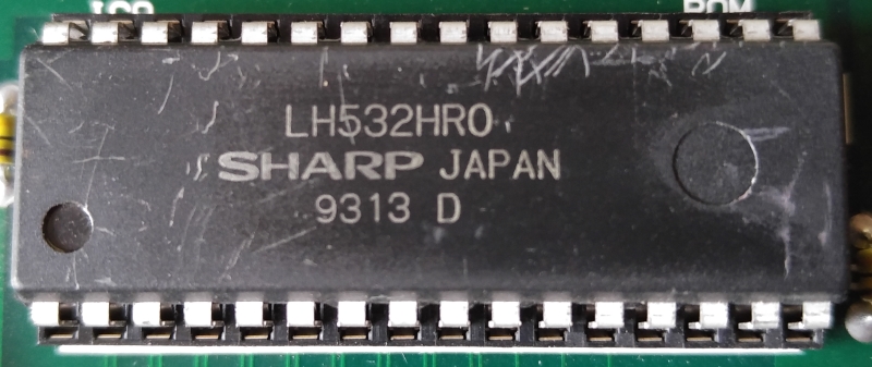
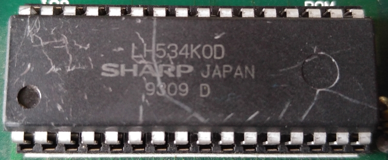
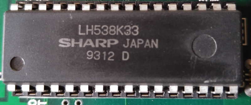
It is possible to determine which to dump these as from the markings on the chip. They all begin with the ID LH53#, where # is the identifier of the size.
“LH532” = 27C020 dump
020

“LH534” = 27C040 dump
040

“LH538” = 27C080 dump
080

The remaining letters/numbers of the markings are unique to the game and location on the PCB.

 Posted by at 10:55 am