The Lethal Enforcers guns arrived today.
On testing I found that the RED gun aiming was off a little to the right and the BLUE gun didn’t register a shot on screen but it did register when the trigger was pressed.
I fixed the RED gun simply by removing and cleaning the lens.
When I opened the blue gun a few bits dropped out, the photo transistor and the spring that pushes the trigger back out.
The photo transistor had simply been dislodged.
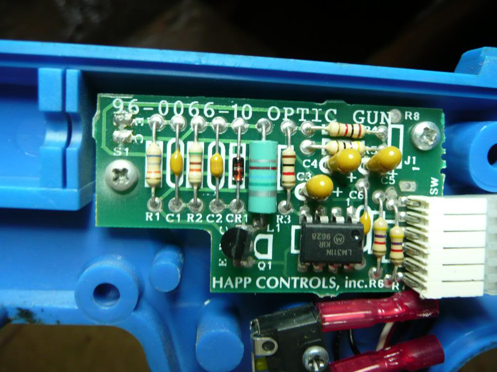
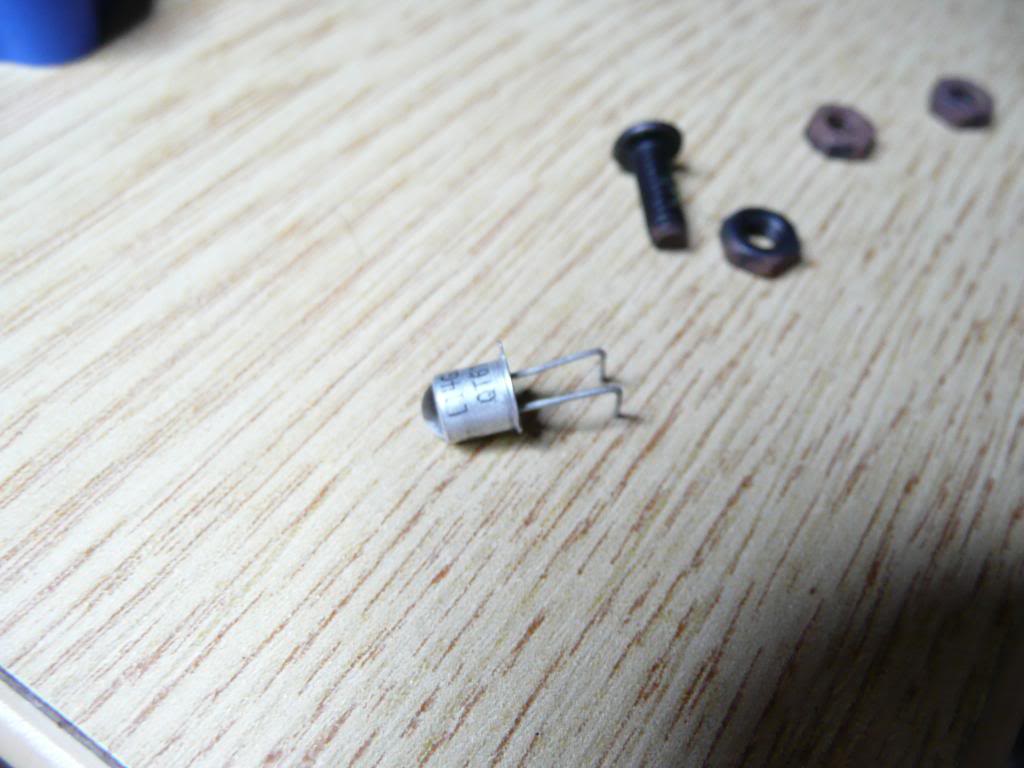
I cleaned up the solder holes and resoldered the part back onto the small PCB.
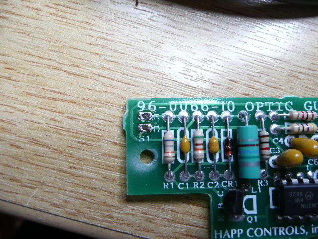
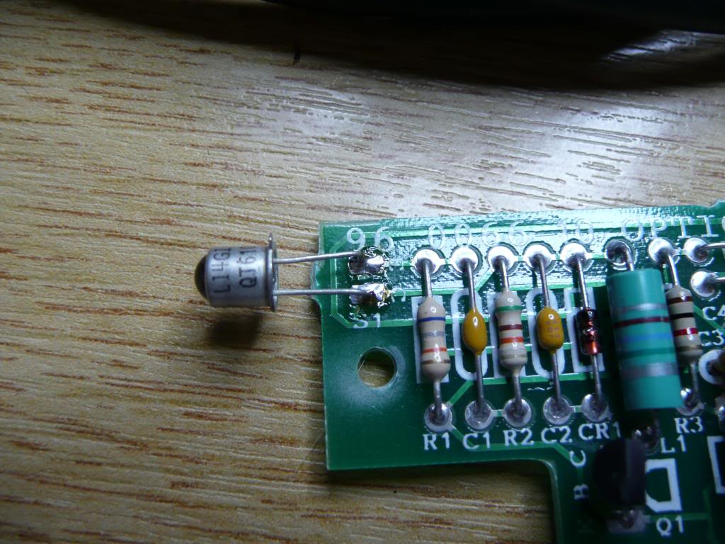
I decided to give this lens a clean too as it had a big greasy fingerprint right on the middle of it.
The hardest part of this repair was getting the bloody spring back in place and to keep it there for long enought to put the gun back together. After a lot of bad noise I managed it. Ive taken a couple of pictures just in case anyone else needs to know how the spring actually goes back in.
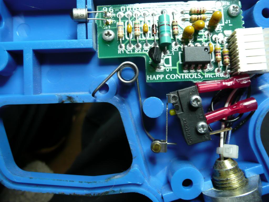
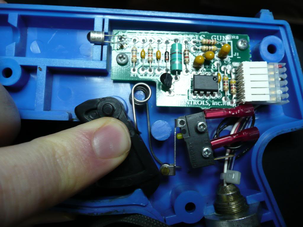
I retested the guns and the RED one works perfectly but the BLUE one doesn’t register shots fired around the edges. This is usually a common problem with older monitors as their brightness fades over time and the guns fail to register the screen flash. I know this shouldn’t be a problem with mine but I also know that components degrade over time too. I removed the bezel glass from my cab as it is slightly tinted and the BLUE gun now works perfectly. I will probably order a new photo transistor at some point, or possibly a new glass bezel!
Lethal Enforcers repair log #1
I decided to take a look at the Lethal Enforcers board I recently bought as it had no sound.
There are many accounts of people with this problem on the forums for this board and the X-Men board, they use the same IC.
I found an excellent post over on the KLOV forums here and decided to see what I could do.
I scraped away the resin around the capacitors and with my multimeter checked continuity following the diagram user tkrn had posted in the above thread.
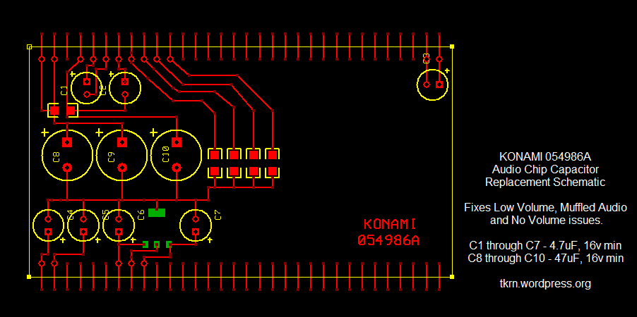
Capacitor C6 had leaked a little and had corroded the track between the positive side and the first pin of the 3 pin IC next to it. I removed the capacitor with a set on small pliers, it came off very easily, and replaced it plus I bridged the corroded track too.
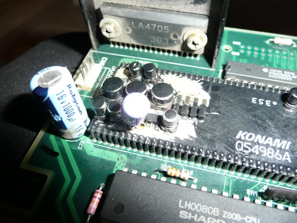
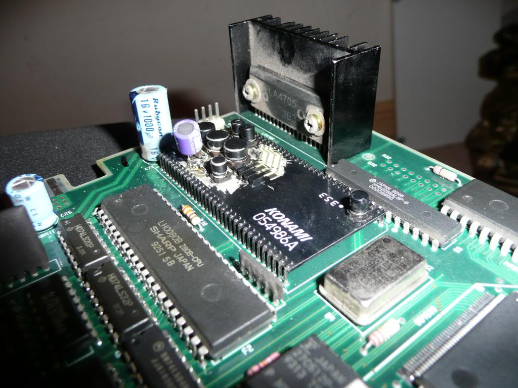
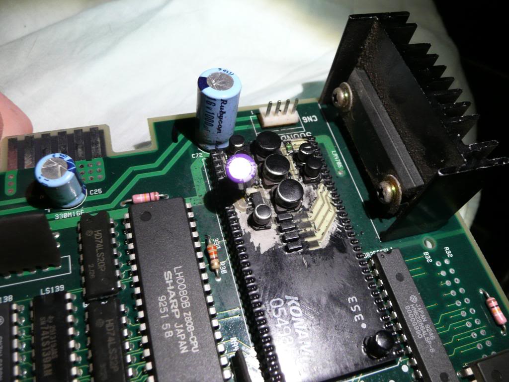
Fired the board up and full sound is back. I haven’t replaced any of the other capacitors yet as its working but when I take this board out and store it I will probably do so just for the sake of longevity.
Many thanks to tkrn over at the KLOV forums for his excellent post, without it I wouldn’t have attempted this fix.
Bubble Bobble repair log #2
Symptom: No RGB output
Cure: Traced the Red signal back to pin 6 on an LS32 (IC57) on video board, it was dead. socketed and replaced the IC and everything is back
Note: This was a (Super) Bobble Bobble bootleg board but I think the majority of the layout etc is the same
Double Dragon repair log #2
This board had no sound, a common fault with Double dragon boards.
I Replaced the 3 op amp IC’s as they were giving no output and the sound is fully working again.
Nice and easy
Funky Jet repair log
The game had way too much yellow on screen, almost impossible to see anything other than yellow.
I Traced blue/green circuit back to palette RAMs K8 and K9. Both looked fine on the scope so had to desolder the pair of them. The RAM at K8 failed a test . Socketed and replaced the faulty RAM with a 2018 and tested.
All working fine
