PAL UpdatesComments Off on Bagman and Namco System 2 PAL dumps added
Aug052017
A quick PAL update today.
‘coolmod’ sent it a dump from a Bagman PCB, device is an unlocked PAL16R6.Since his PCB is faulty we have no means to test a GAL16V8 replacement so we mark this dump as “assumed working”.Thanks to him anyway.
I redumped the PAL marked ‘SYS87B-3’ (@8D on CPU board) from an Ordyne PCB (Namco System 2 hardware) and successfully reversed and tested into a GAL22V10.This replaces the native PAL12L10 dump we had.
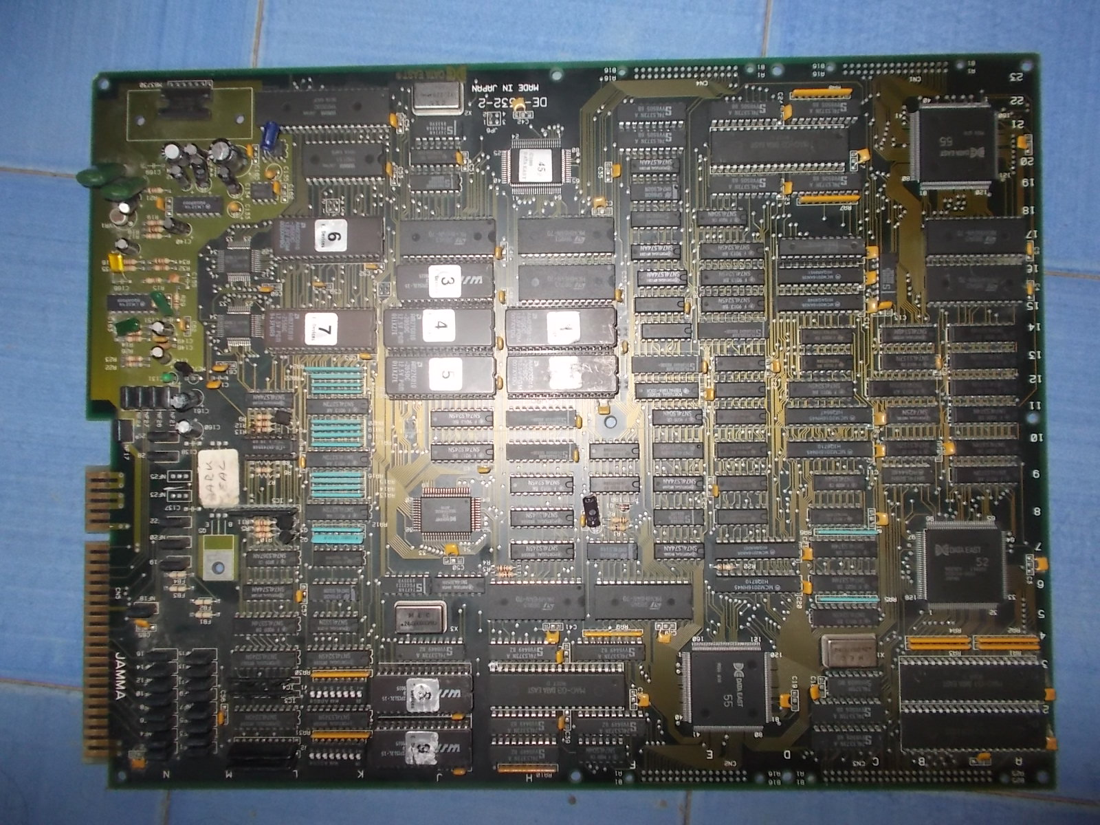
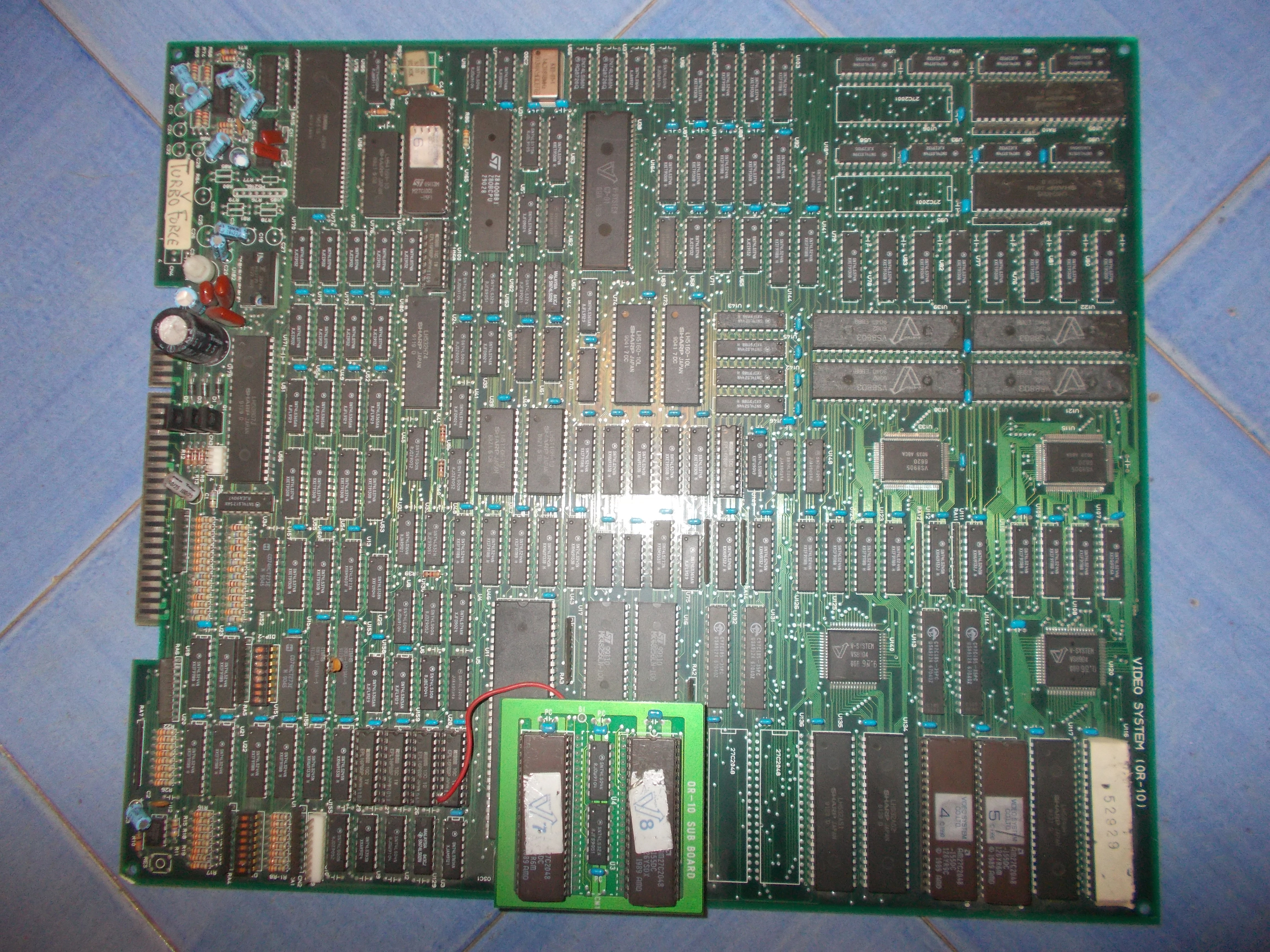
Got a Dark Seal PCB in a lot of faulty boards recently acquired.For the uninitiated Dark Seal (also known as Gate of Doom in USA) is an action game with isometric perspective and R.P.G. elements released by Data East in 1990.
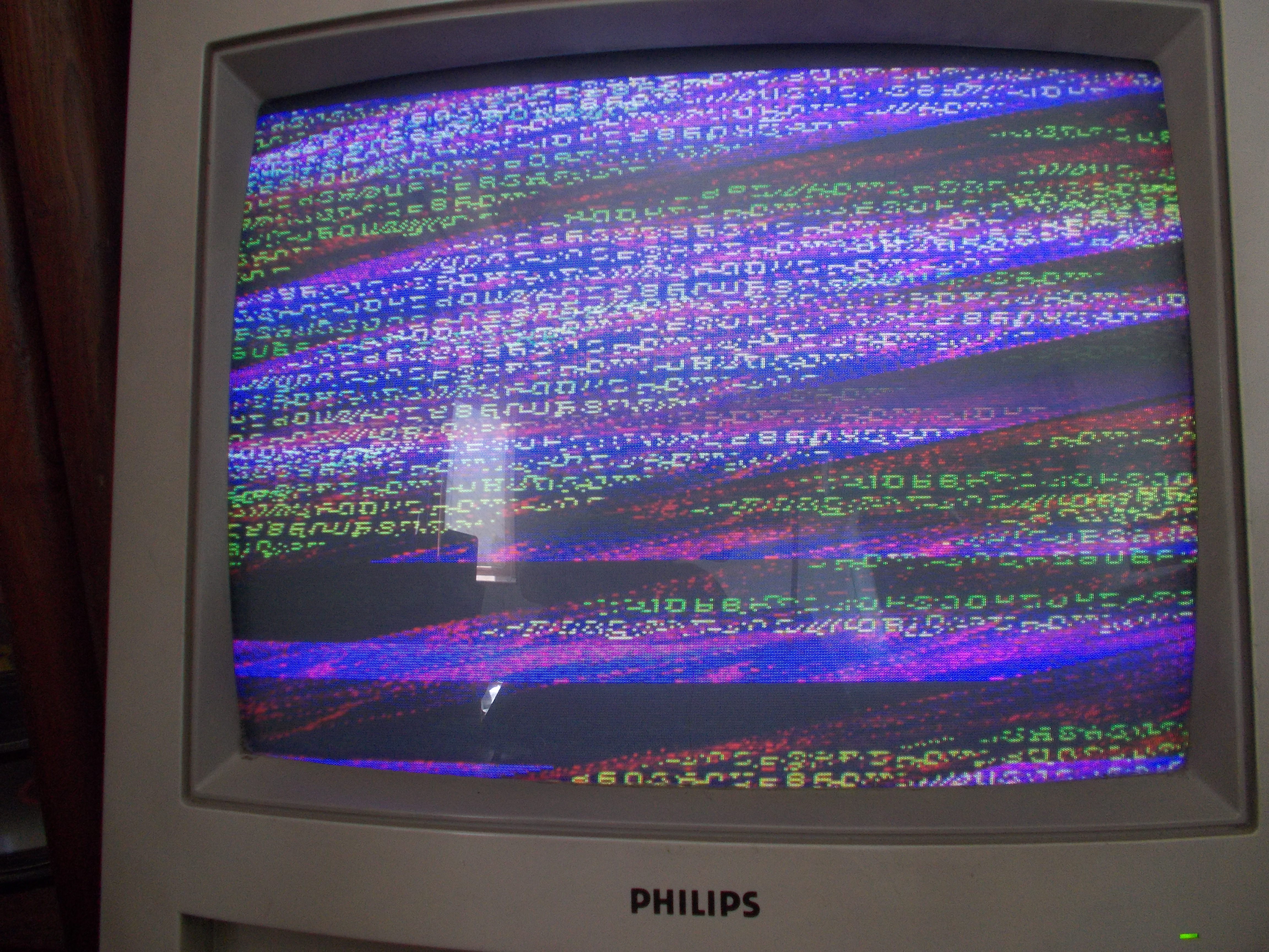
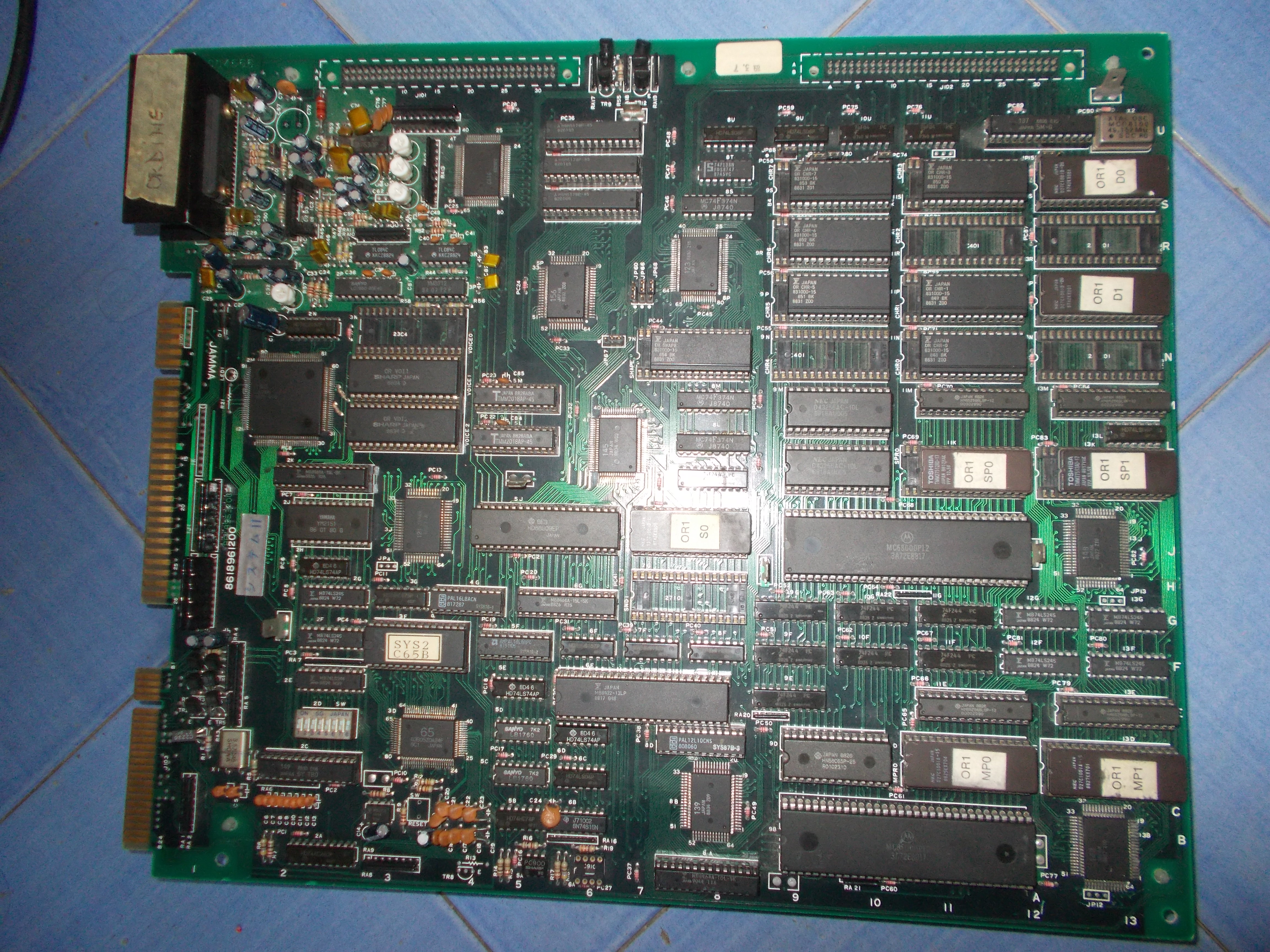
My board did nothing upon boot giving a solid black screen.Applying pressure on one of the custom ’55’ (the one in the upper right corner) restored the video output, a closer inspection revealed some lifted pins so I did a reflow.I got stable video output now and could play the game but image was rolling, this was a clear sign that SYNC signal was missing :
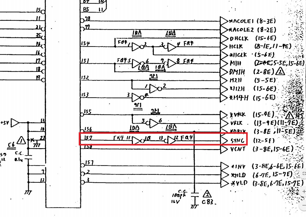
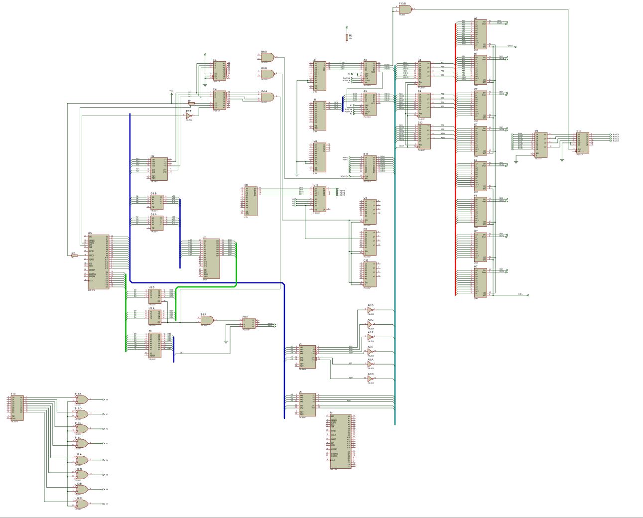
There are no documentation available but other Data East games share same design.Desert Assaul for example, here’s a snippet from its schematics :
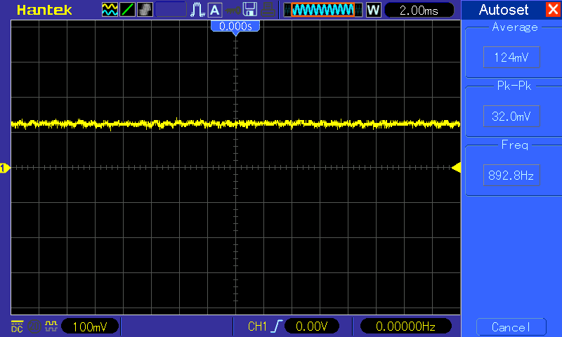
As you can see SYNC signal is generated by pin 157 of the custom ’55’ and then inverted two times by a 74LS04 before reaching the JAMMA edge.I could measure a good signal on this pin :
but nothing on pin 13 solder side of JAMMA connector :
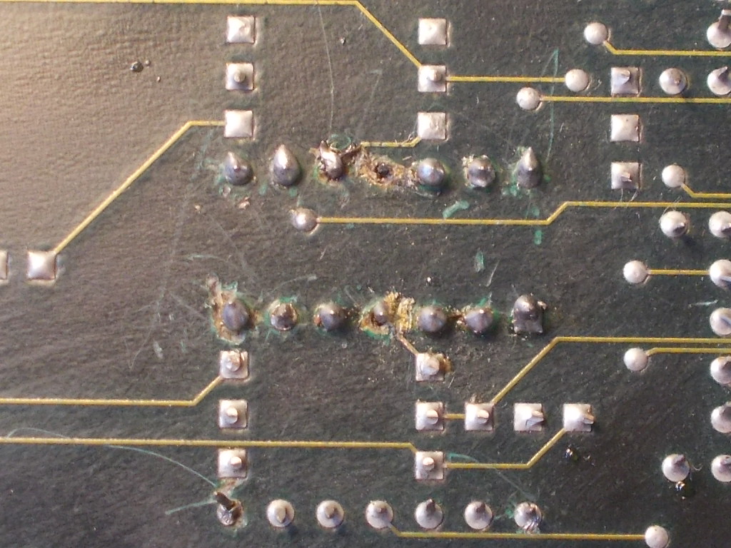
So the problem was in the middle.Looking at solder side of board I noticed the area of the 74LS04 that inverts the SYNC signal has been badly reworked in order to socket the TTL itself, some rivets were ripped off:
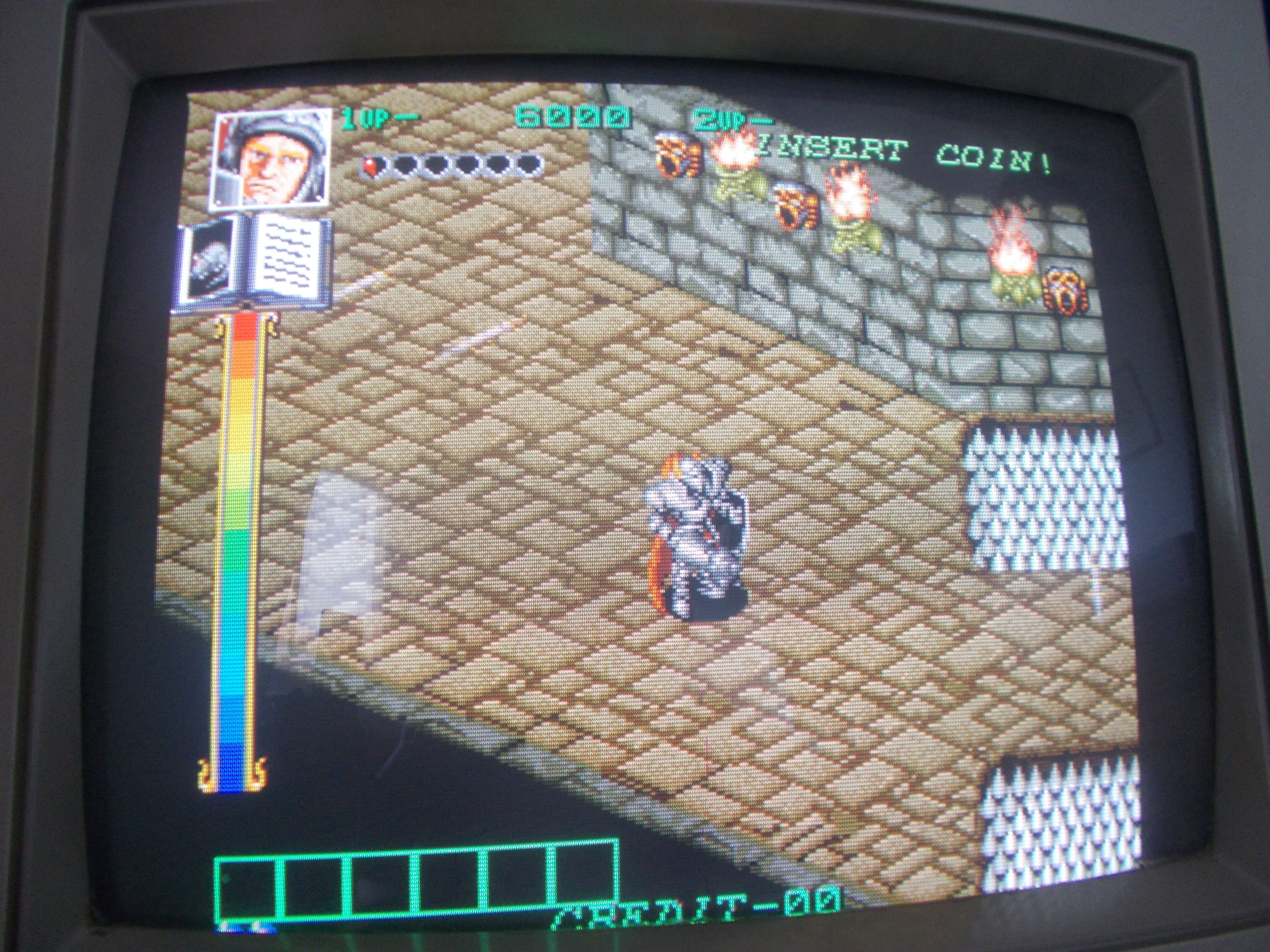
Signal was present on pin 1 of the 74LS04 and correclty inverted on pin 2 but, following the scheme of Desert Assault, it was absent on the adjacent pin 3 (pin 4 is connected to JAMMA SYNC pin via a 47Ohm resistor) so the trace between pin 2 and 3 of the inverter had been severed by the previous attempt repair.I simply bridged these two pins restoring the SYNC on JAMMA.But, once I got a stable image, I noticed the blue color was very strong and after some time it disappeared causing a yellowish screen:
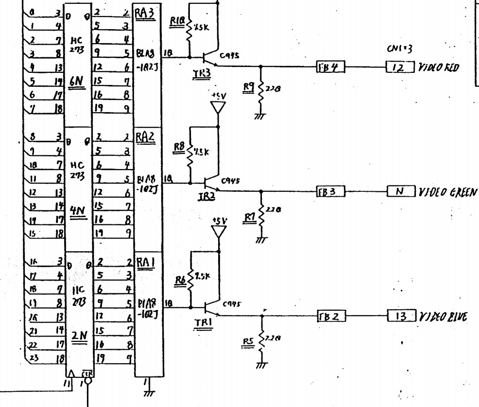
Color generation circuit is pretty the same of Desert Assault:
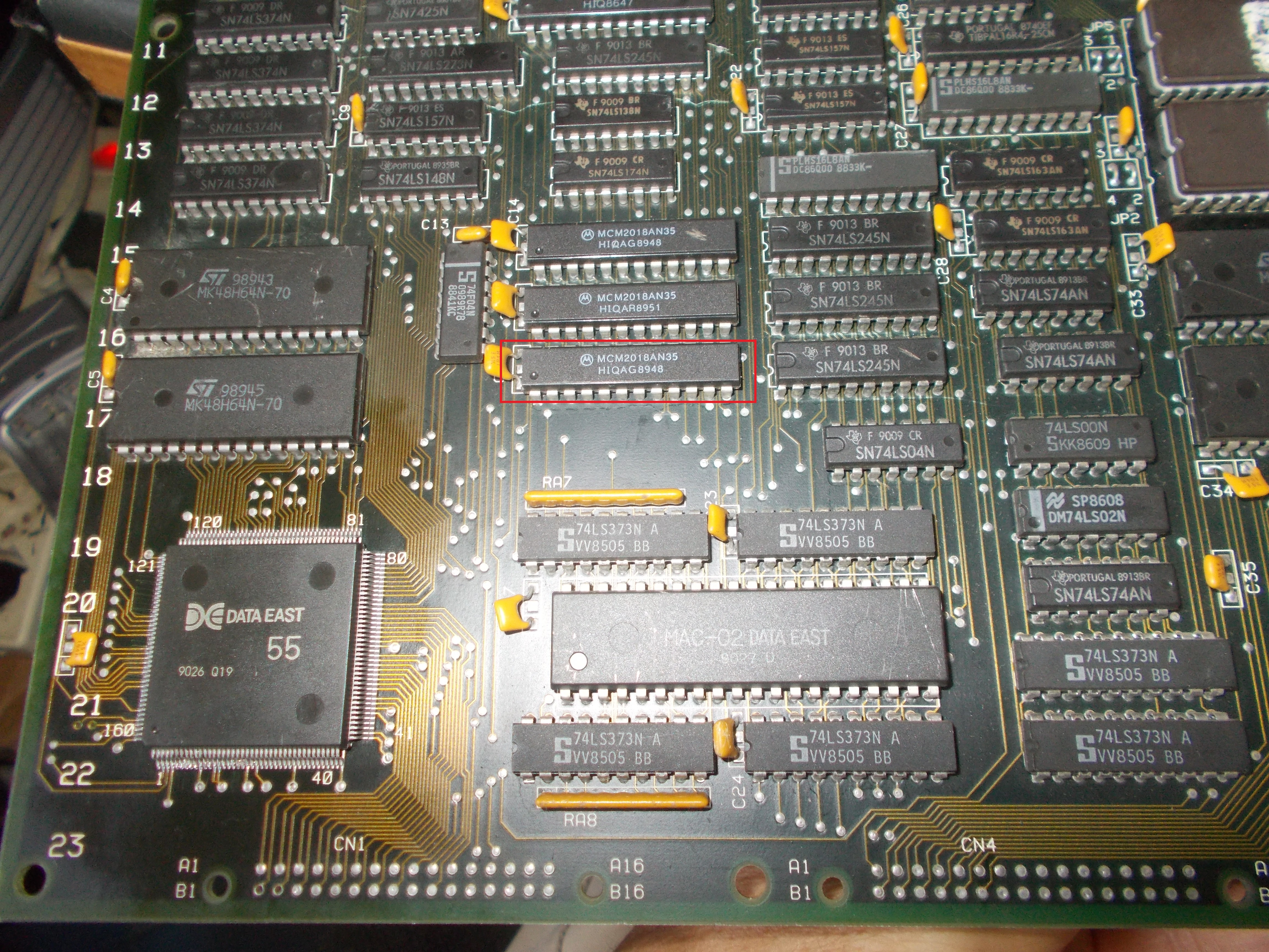
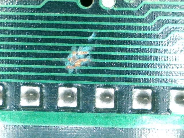
As you can see bits of the tree colors from the 8-bit latches are converted to analog by a resistor ladder and, lastly, each color is amplified by an NPN transistor.Signal was absent on the emitter and base of transistor so problem was upstream.Going back I found nothing abnormal until I got to the palette RAMs, three 2018 :
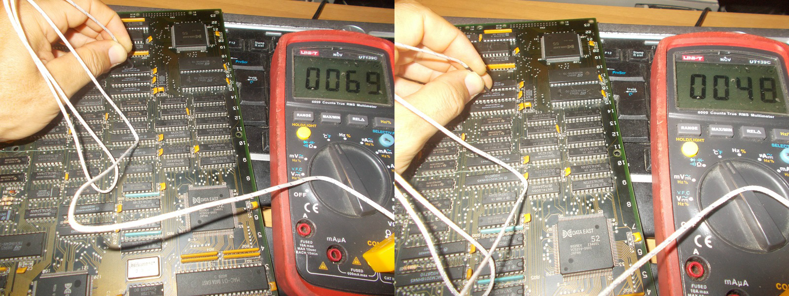
The one highlighted in the above picture was burning hot to the touch, with a termocouple I could measure an external temperature of 69°C compared to 48°C of the other two (RAMs in palette circuitry run usually warmer than other since they have greater power dissipation due very fast access time, 35ns on these ones)
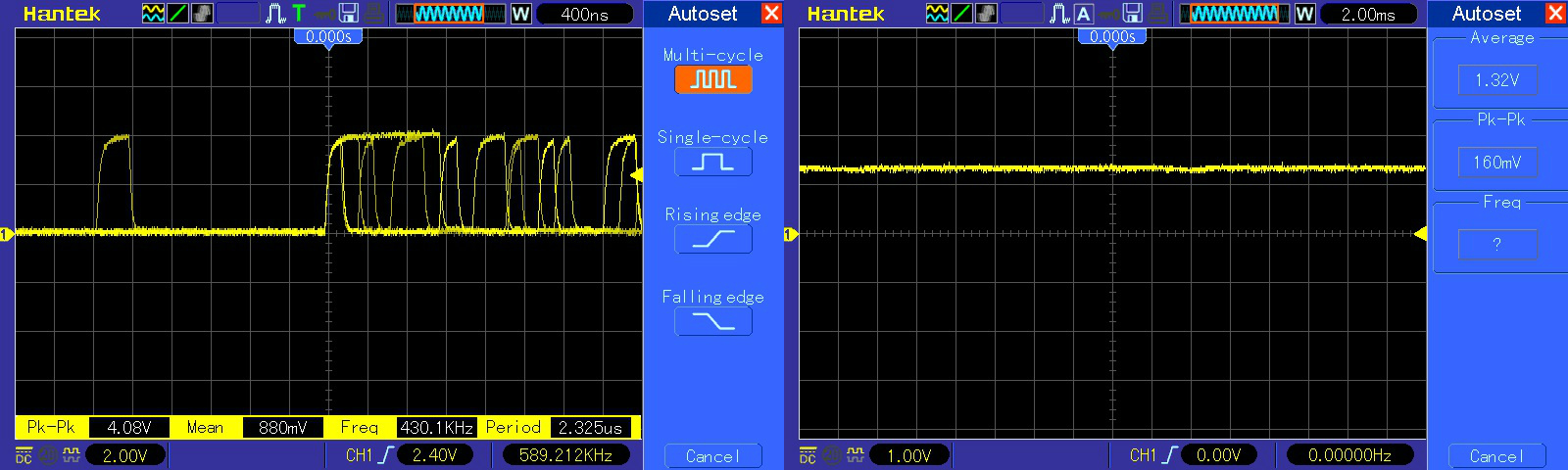
Analyzing the suspicious RAM with a scope revealed all data lines were stuck low (healtly signal on left, bad on right of the below picture)
Once removed, the chip failed the out-of-circuit test:
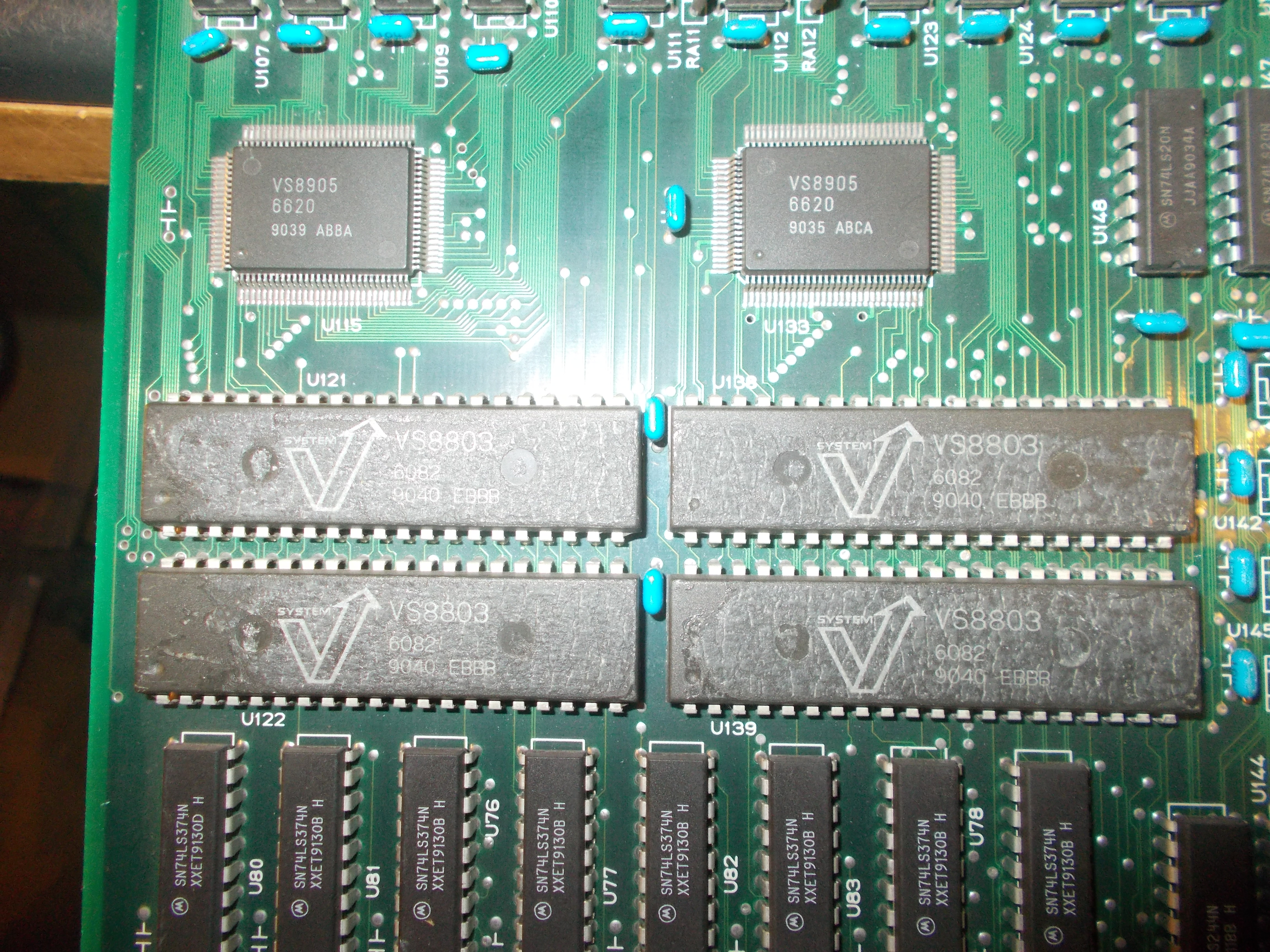
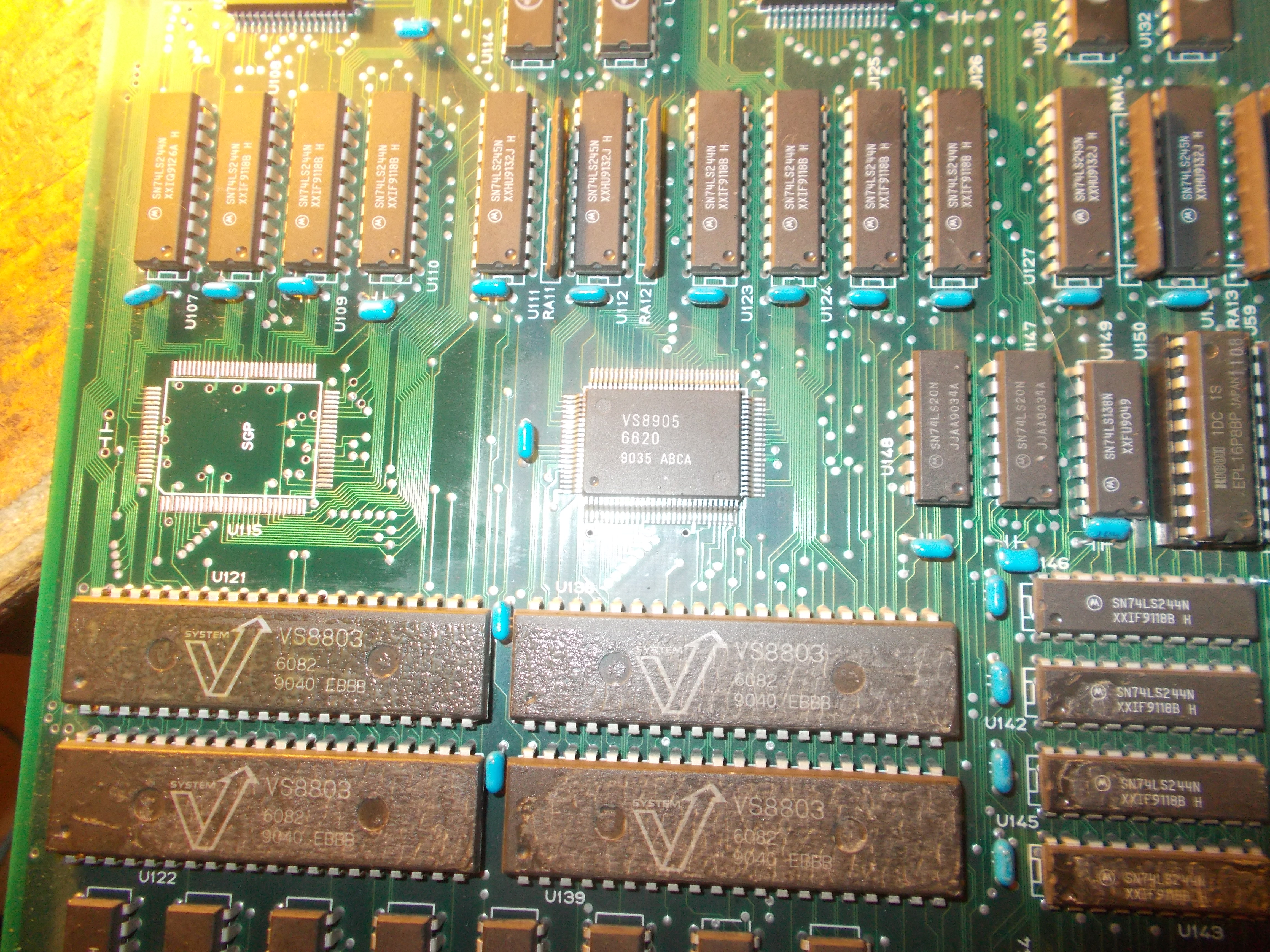
In first repair the issue was due a faulty ‘VS8905’ sprites address generator (there are two of them on PCB)
When I put my fingers on the one @U115 (same location of the faulty one in previous repair) it was quite hot, this was a clear sign that internal junctions were bad and a proof that this part is prone to failure.I removed and replaced it:
My board was faulty since it was sitting after performing the SELF-TEST without reporting any error :
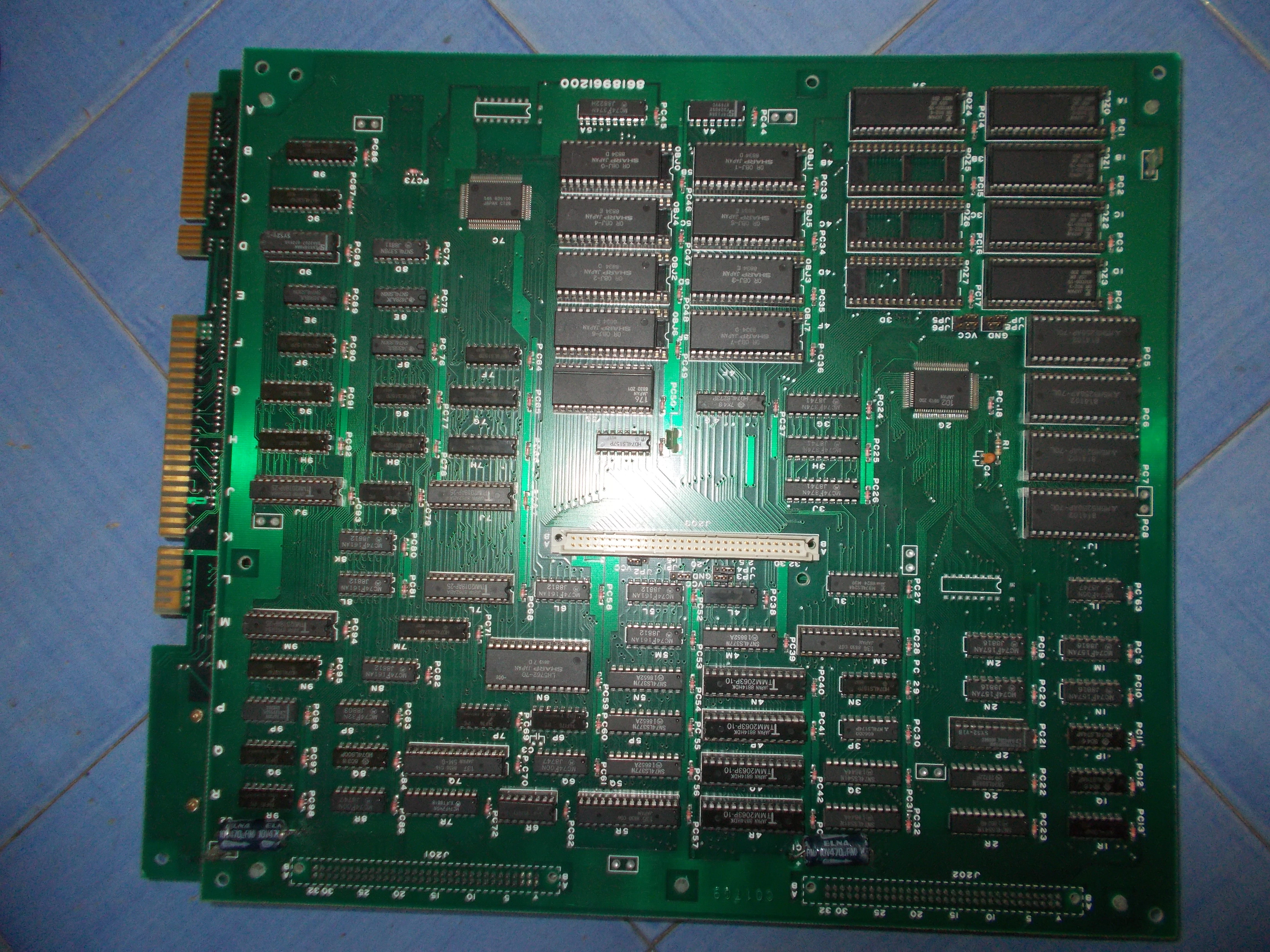
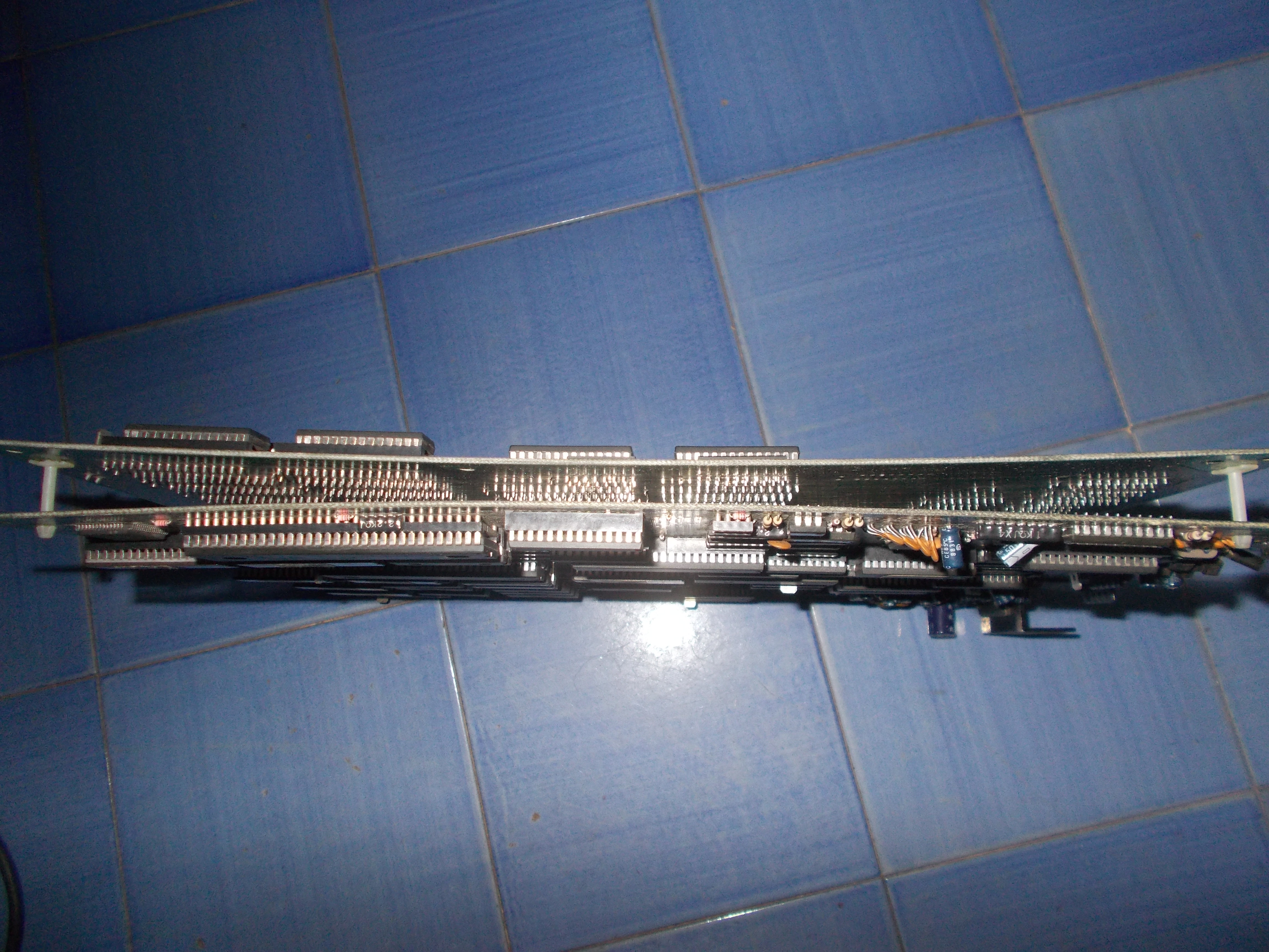
First of all I swapped a good motherboard but this didn’t lead to any improvement so the fault was located on VIDEO board.At a closer inspection I found some scratches on solderside of this board:
One trace was really severed, it was the one connected to pin 9 of the KEY custom ‘176’.Problem was caused due the board has been crushed under some weight hence solder sides of the two boards were touching and scratching each other:
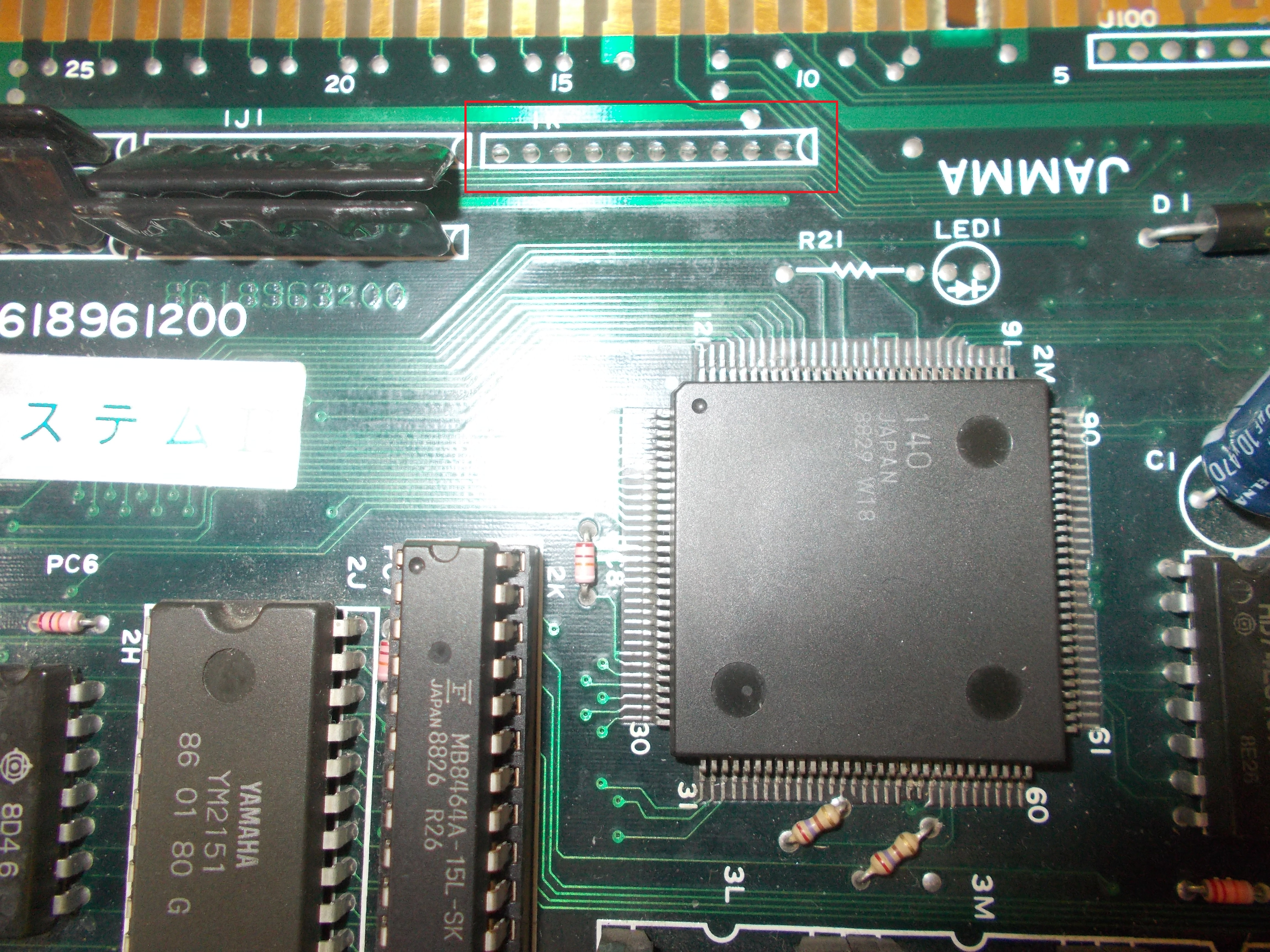
After patched the trace, the board successfully entered in game but I could not coin up.I quickly pinpointed this fault to a missing ‘CUS95’ resistor array @1K near the JAMMA edge: