Shou has successfully tested the decrypted set for Turbo Outrun (317-0101).
Thanks to Shou for giving feedback !

Shou has successfully tested the decrypted set for Turbo Outrun (317-0101).
Thanks to Shou for giving feedback !
New contributor time again. This time cpsystem3 has joined us.
Welcome!
Had this board for a while now but hadn’t looked at it.
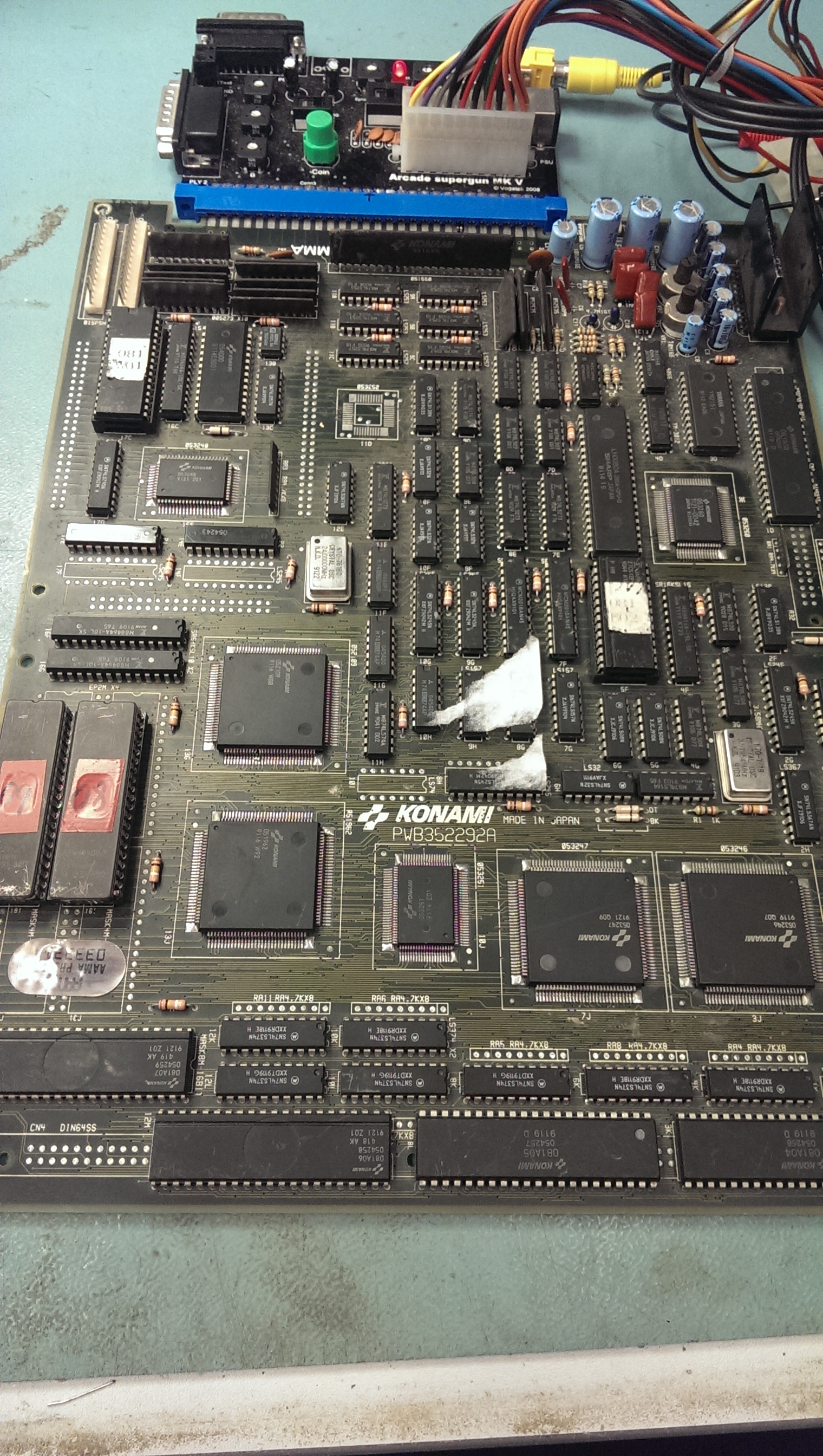
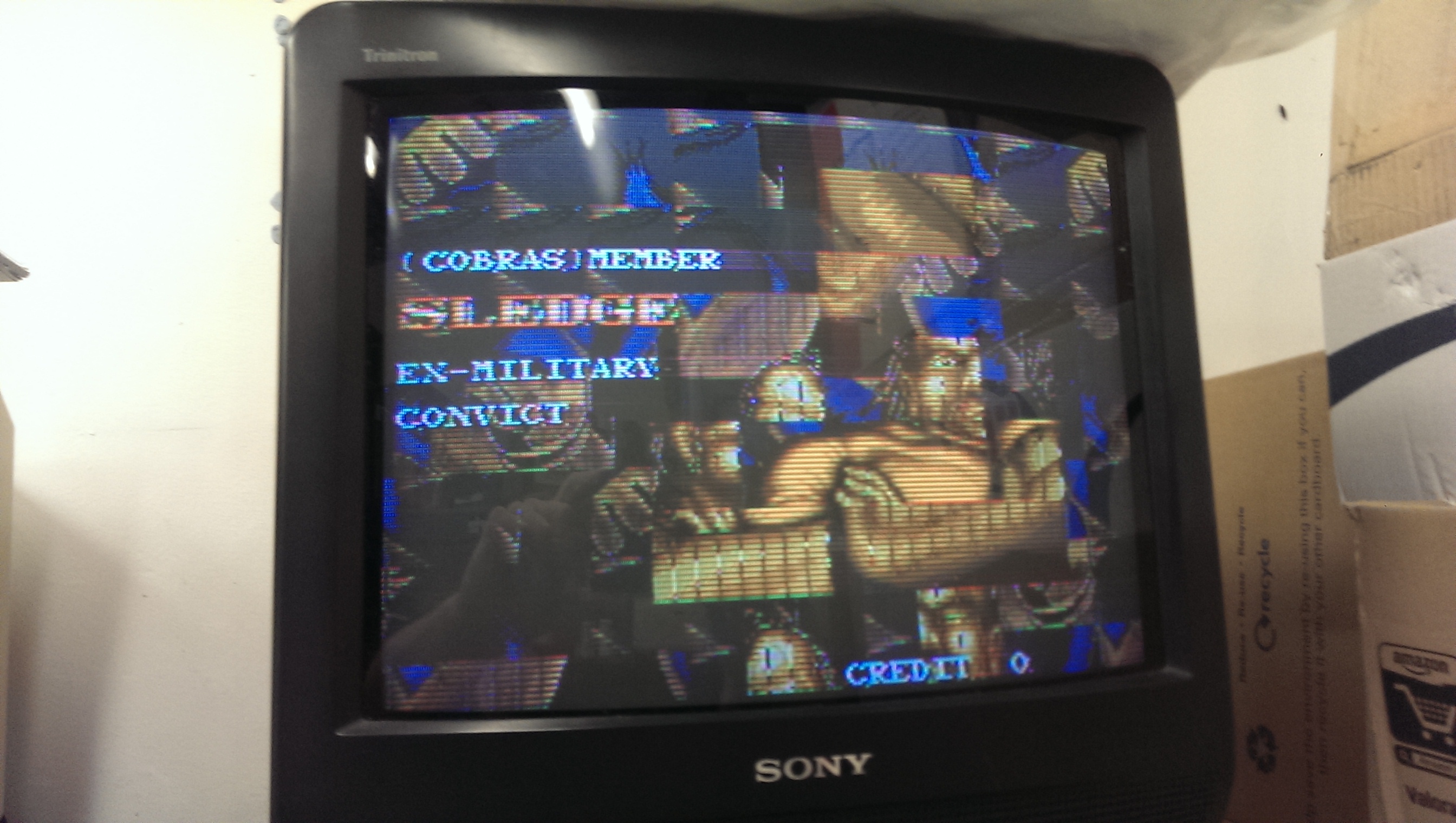
On booting the board up I got completely messed up graphics.
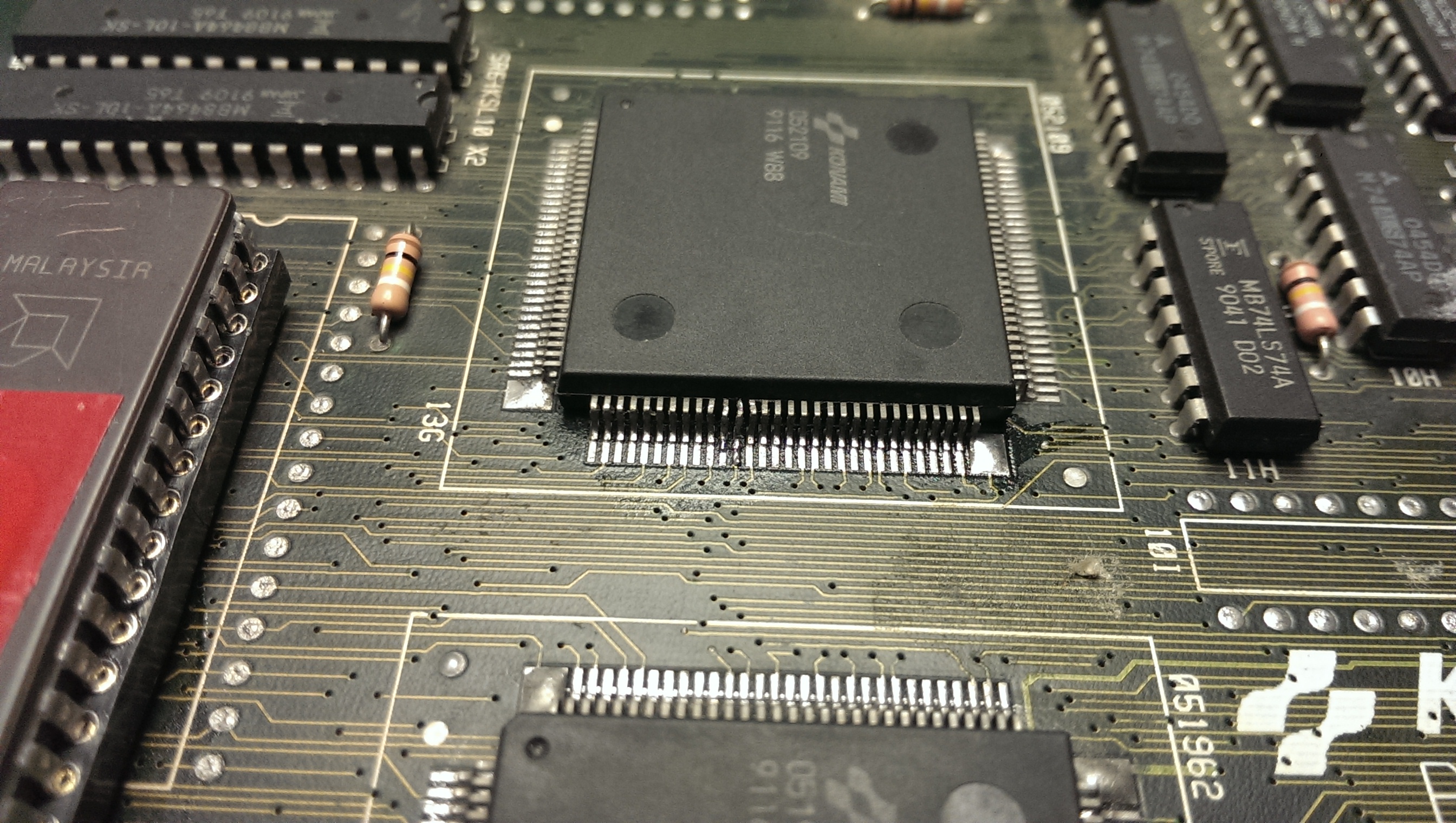
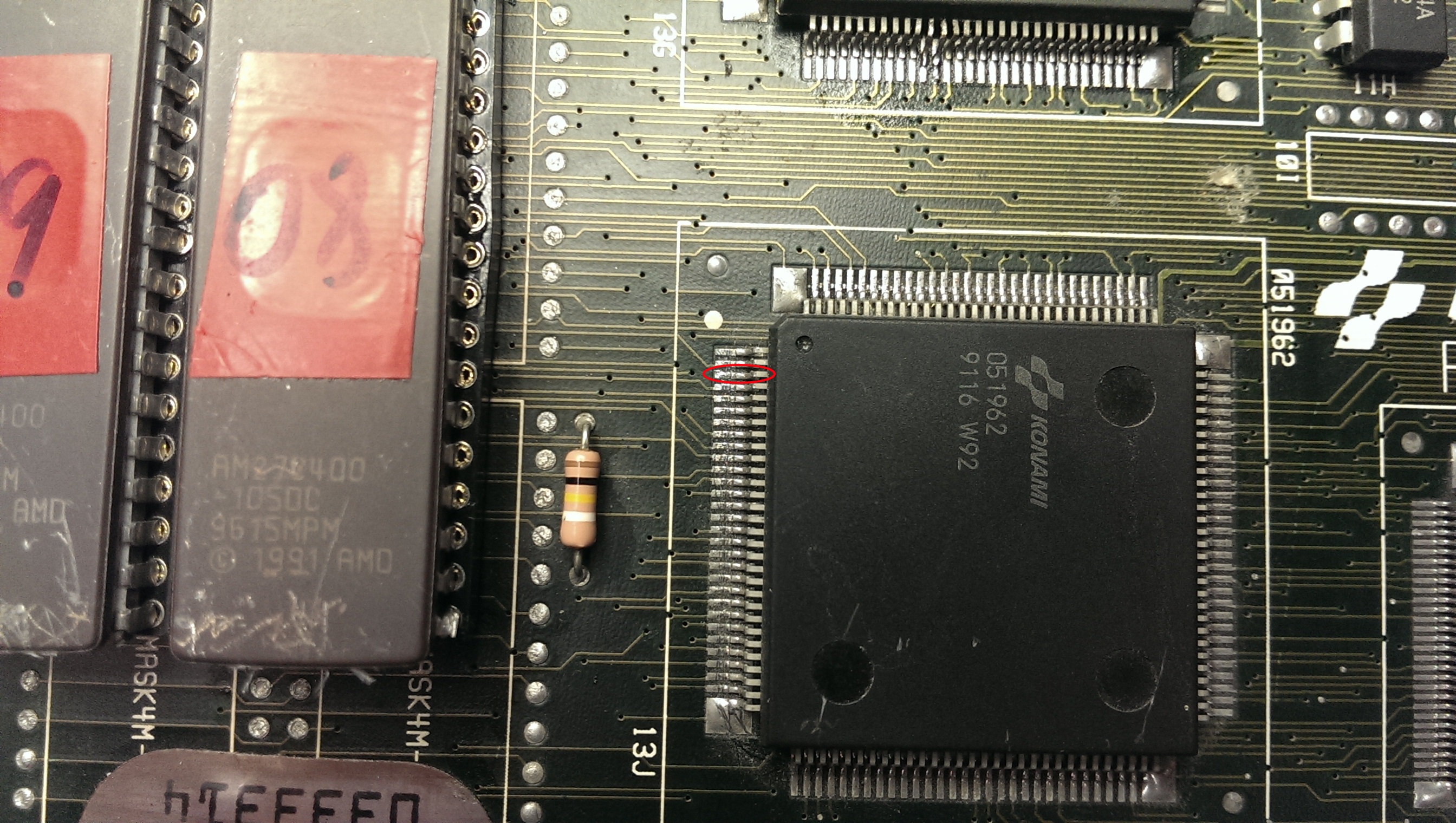
On my pre power up visual inspection I somehow missed the damage and solder blob on the 052109 tilemap generator.
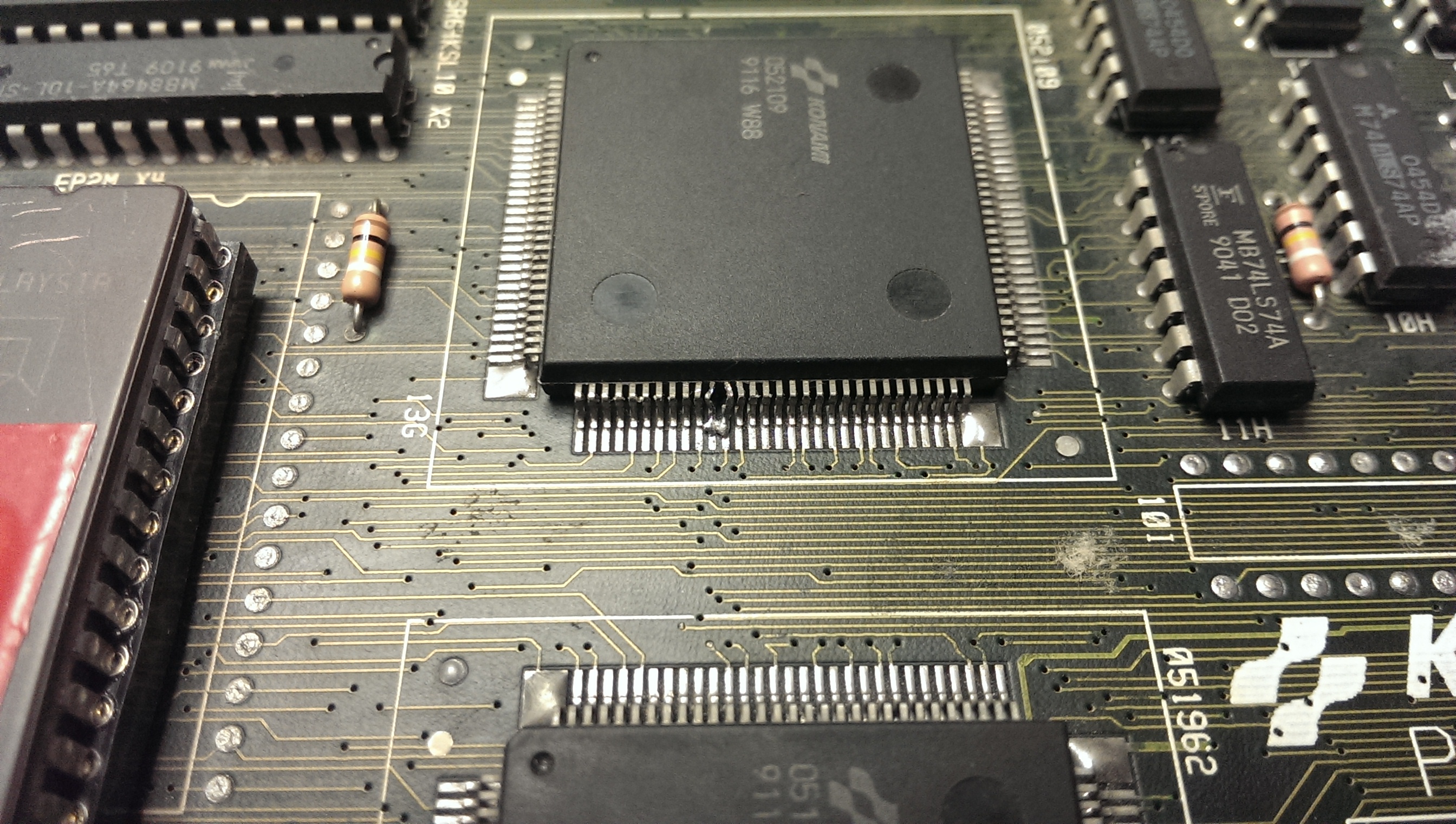
I removed the solder using solder braid and straightened the legs up best I could with some fine tweezers. It took a while as I didn’t want to snap the legs off but I ended up with something I was happy with.
Fixing that gave me the graphics back but there were jailbars present.
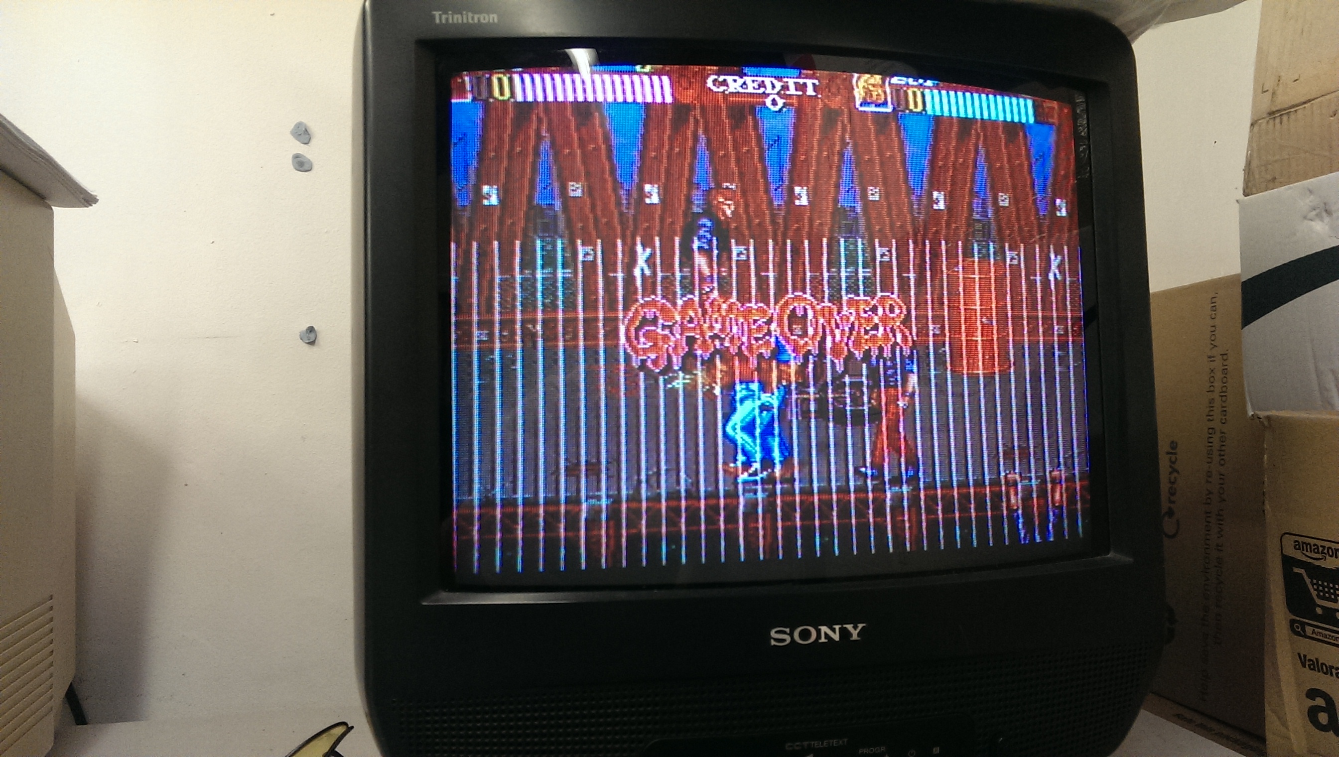
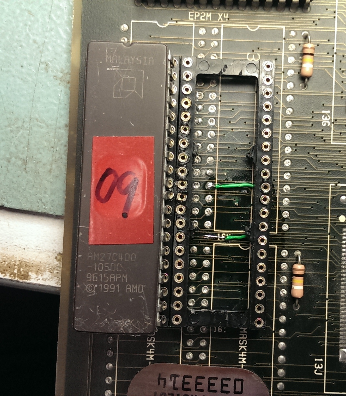
Jailbars are usually a sign of a failed ROM and as the two MASKROM’s have previously been replaced for a pair of 27C400 EPROM’s I thought it was best I check these out first.
Both turned out to be fine so the next step was to check the address and data line to see if they were active.
Again I could find no problems here.
I then found the test menu which runs a self test on these ROM’s. The ROM at location 16I gave a different checksum each time I ran the test. A changing checksum can be a sign of a floating data pin. I already knew the data pins were active and that the ROM’s were good so I set to work with the multimeter checking continuity between the EPROM and the 051962 tilemap generator which these data line go to.
Eventually I found data pin 8 did not make it to the 051962.
I was able to patch this underneath the EPROM so it would be hidden (and protected).
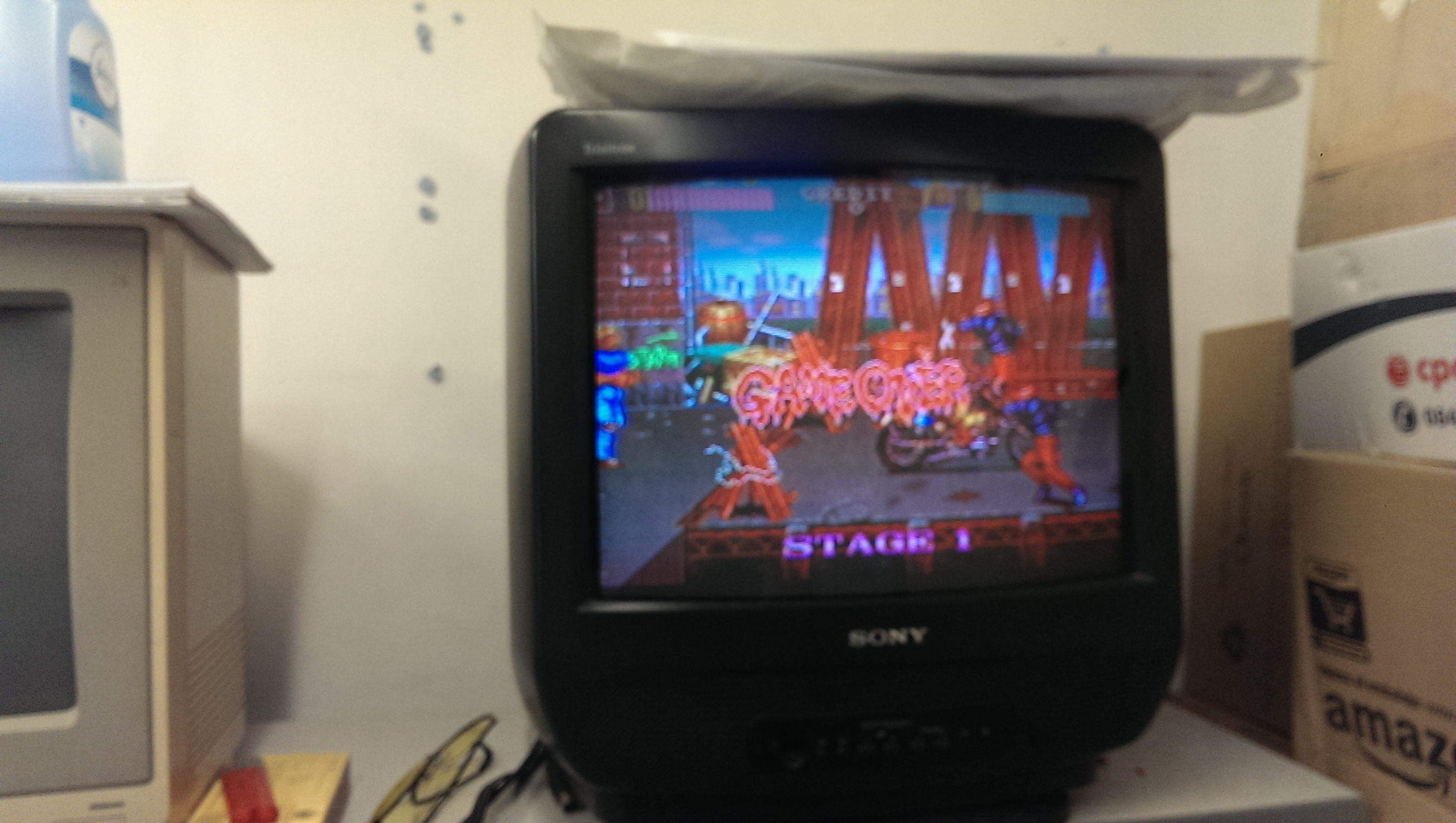
On powering up all the jailbars were gone and the board is fixed.
rtw has successfully tested the decrypted set for Tetris (317-0092).
Thanks to rtw for giving feedback.
Layer has recreated and tested the TK63B PAL from Dynasty Wars.
Thanks go to Layer for this.