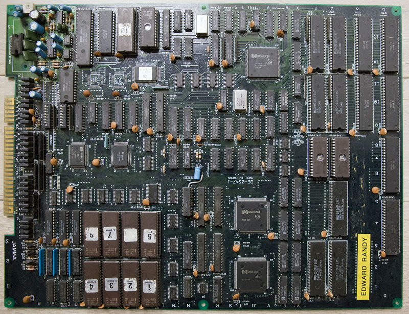
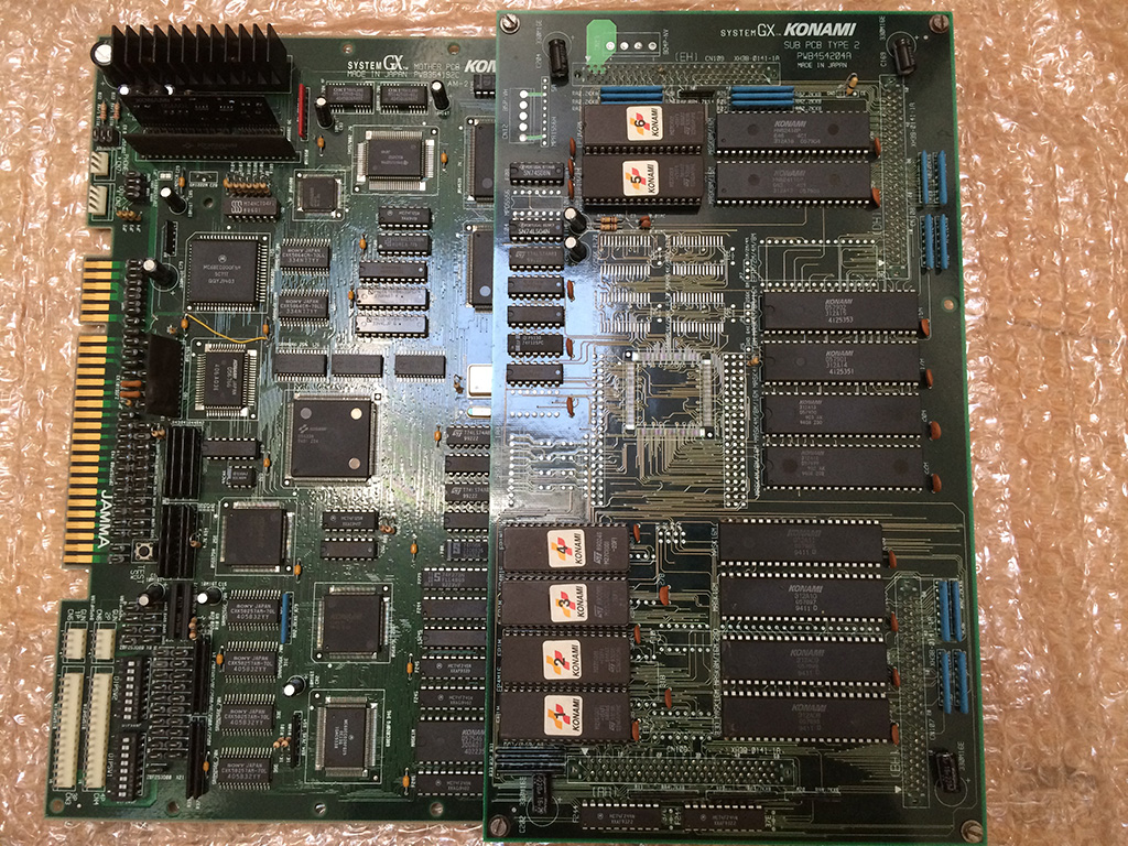
Got this NebulasRay PCB ( converted from another Namco NB-1 game) from my friend Josef for a repair:
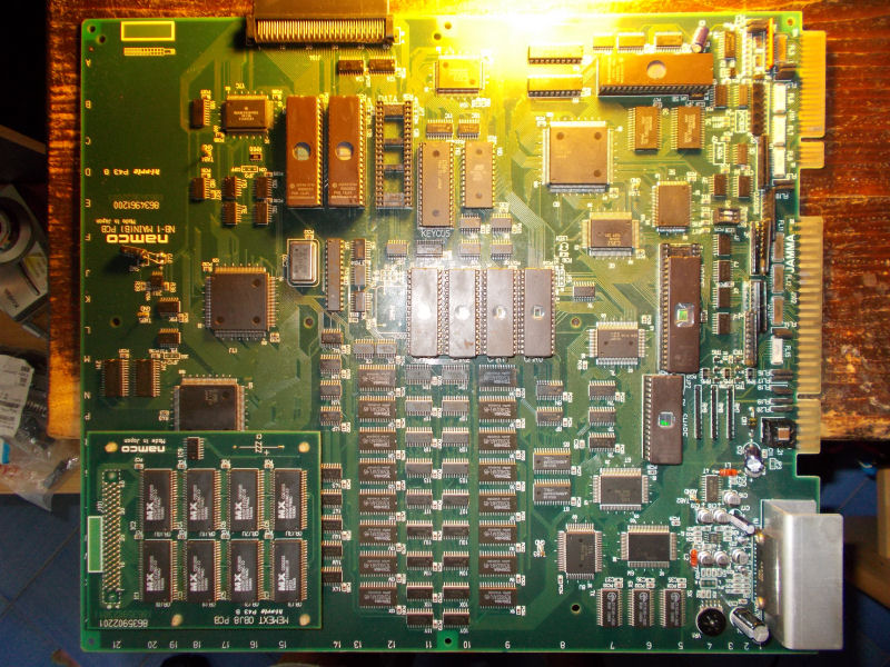
For the uninitiated the game is a vertical shoot ’em up released by Namco in the 1994.It runs on Namco NB-1 platform.Here are the specs:
- Main CPU: Motorola 68EC020 32-bit processor @ 12.5 MHz (for the NB-1 games), 24.192 MHz (for the NB-2 games)
- Secondary CPUs: Namco C329 with C137
- Custom graphics chips: Namco C123, C145, C156 and C116 (for the graphic effects) with Namco C355, C187 and C347 (for the motion objects)
- Sound CPU: Namco C351 (utilized for the NB-1 games), Namco C75 (Motorola M37702-based 16-bit) @ 16.128 MHz (utilized for the NB-2 games)
- PCM sound chip: C352 @ 16.384 MHz that supports 8-bit linear and 8-bit muLaw PCM with four-channel output
- Control chip: Namco C160
- Board composition: two boards (NB-1) or single board (NB-2); an additional “gun” interface board was also utilized for Point Blank.
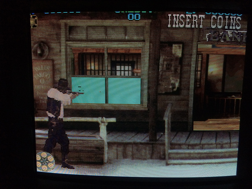
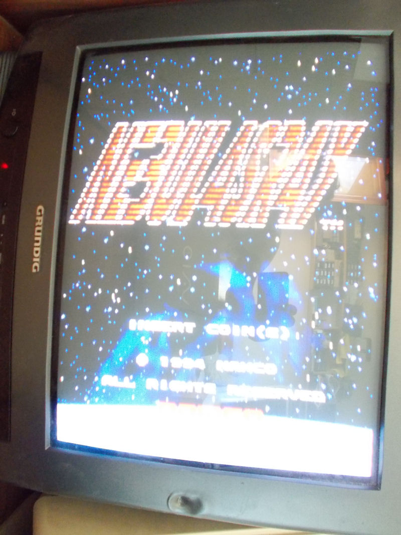
Board actually booted but didn’t pass the disclaimer screen:
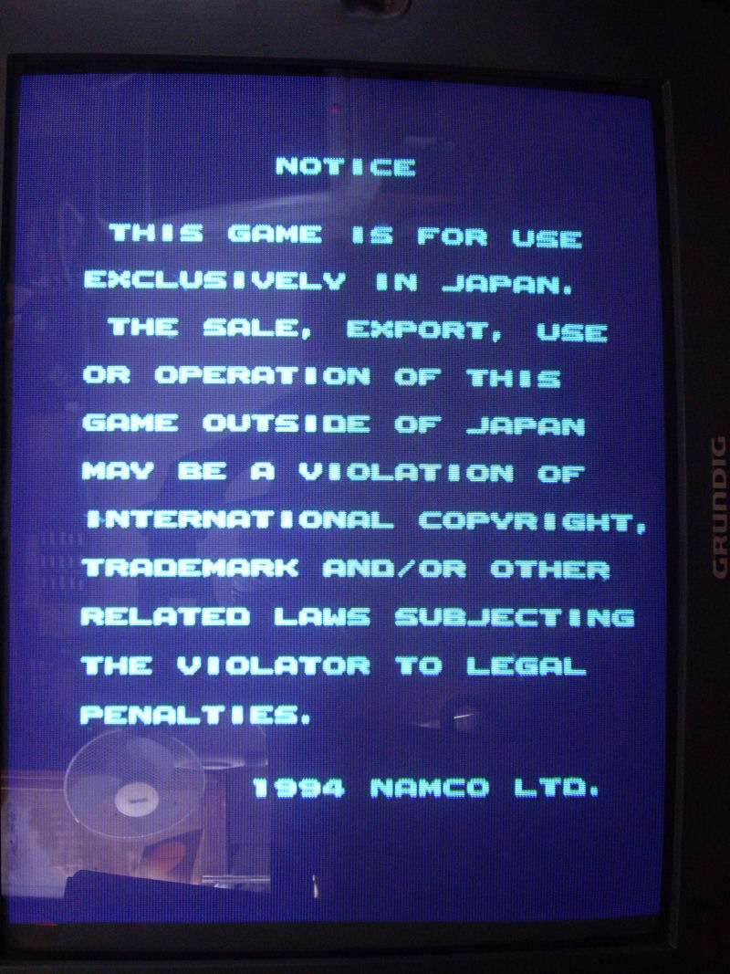
As said, main CPU is a 68EC020.Probing it, revelead a good activity until it got stuck on the above screen, at this point most of control lines were going to high impedance state terminating the BUS activity.So, there had to be some trouble in the main code execution but, given the hardware complexity and lack of documentation, I was pretty lost.
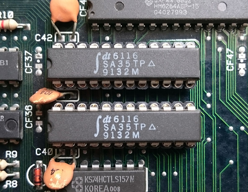
I started to do some tracing on PCB so I could locate the WORK RAMs ( two Toshiba TC551001 @5C and 6C):

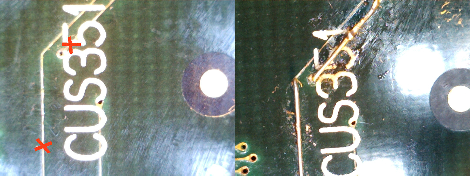
I figured out that they were not addressed directly by main CPU but through the near custom C351 (which is actually the custom sound CPU).I replaced both RAM but without luck.So, I removed the custom C351 and checking traces underneath it I found two breaks which I patched with some tiny wires:
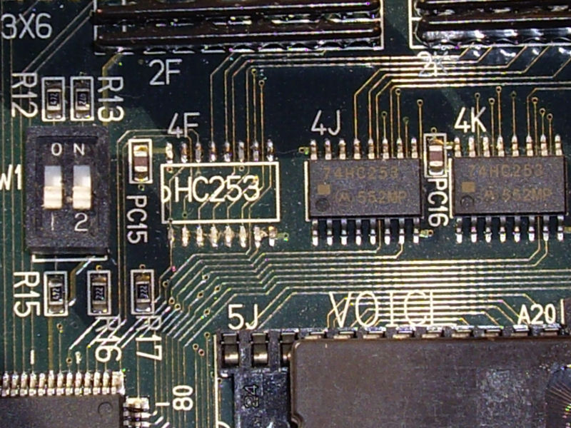
With this fix the board passed the initial disclaimer screen but went straight into test mode although dipswitches were set to off.I quickly traced this to a missing 74HC253 multiplexer @4F:
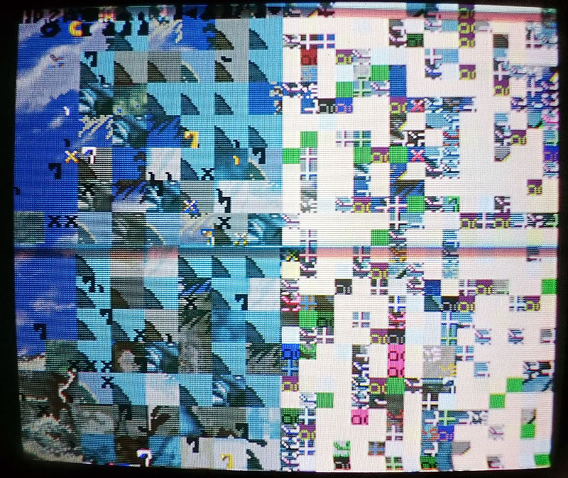
Finally the board entered in game but all sprites were wrong :
![]()
Object RAMs are two Mitsubishi M5M5256 @20M and 21M:
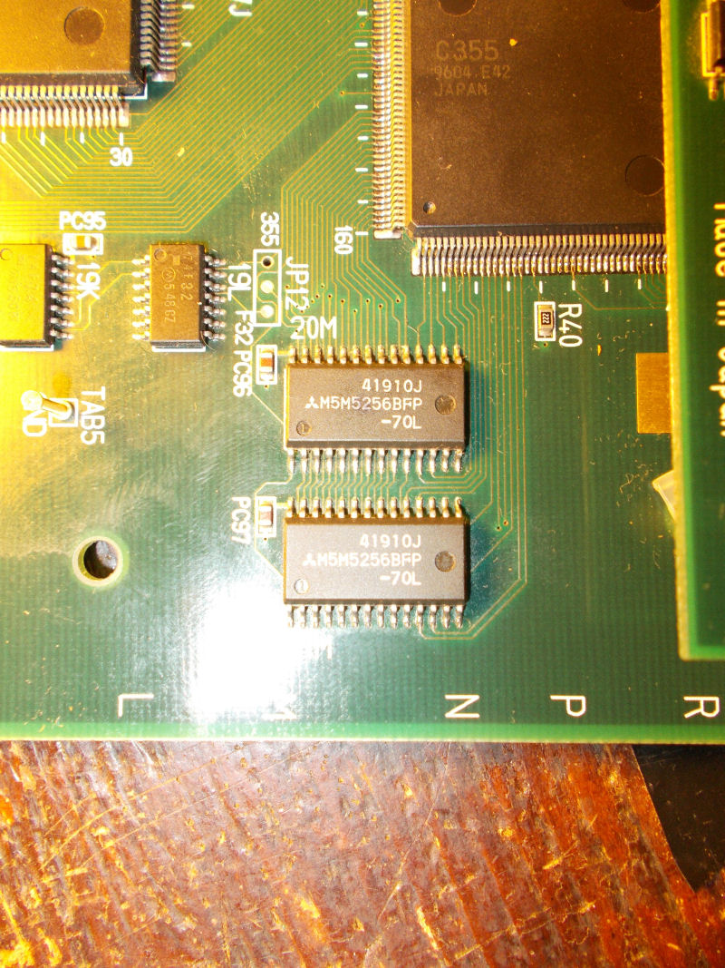
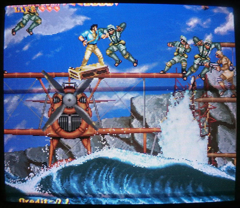
A closer inspection revealed some loose pins that I promptly resoldered.In this way all sprites were restored except for jailbairs on some of them (like game title ):
All sprites ROMs are on the small daughterboard in form of 8 MX29F1610 FLASH devices :
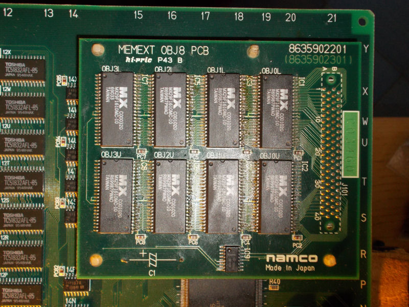
Since the board was a converted one, they were hand soldered not in professional way (let’s say so..) so I reflowed them.Graphics and sound were perfect now but some inputs were missing or stuck like reported in switch test:
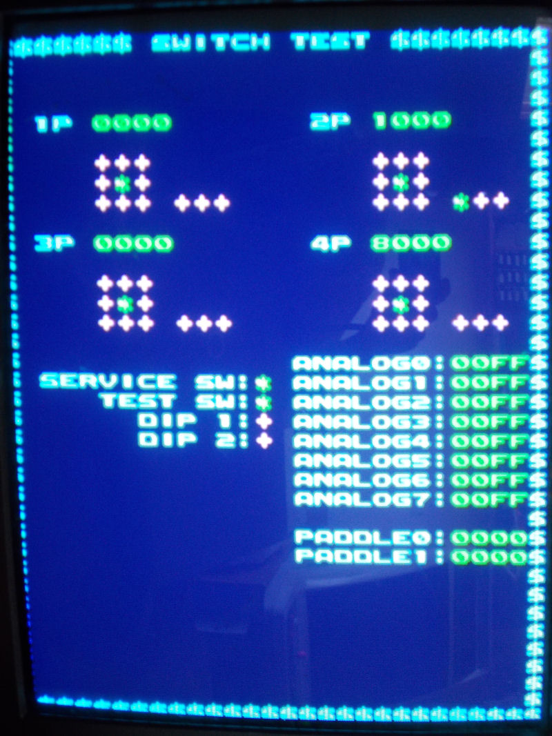
The inputs circuitry is so designed on this kind of hardware : JAMMA connector pin is connected to some EMI filter arrays , then to some custom CUS93 resistor arrays, then to some 74HC253 which combine inputs into outputs that go to the ASIC C160 (which is the I/O chip):
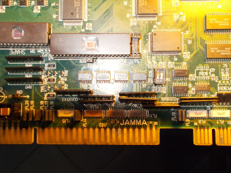
After some tracing I could pinpoint the faults in two bad CUS93 resistor arrays @2L and 1F:
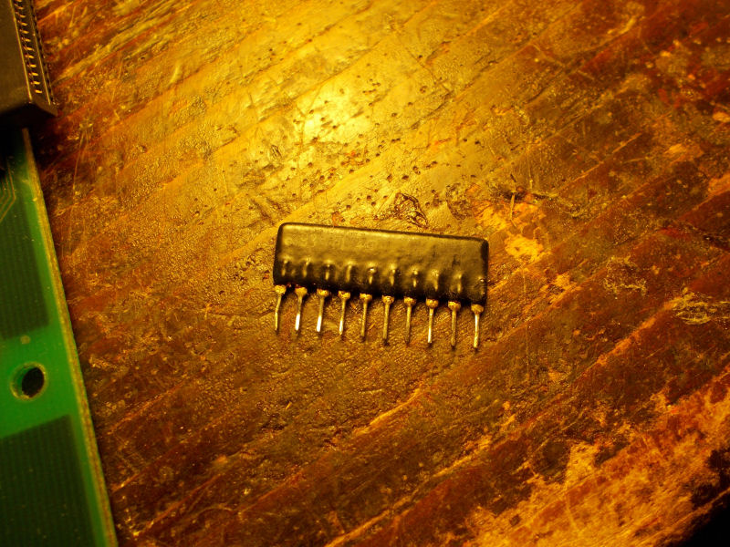
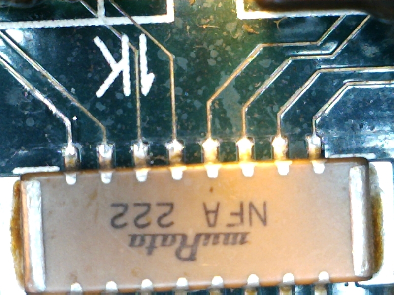
Besides, there was intermittent contact between some pins of JAMMA connector and EMI network filter array @1K:
Board 100% fixed.End of (long..) job.