dj_yt has tested the above decrypted version of E-Swat and all is well.
Thanks to dj_yt for testing and reporting back.
E-Swat 317-0129 tested
Decrypted Updates
Comments Off on E-Swat 317-0129 tested
Feb 042016

dj_yt has tested the above decrypted version of E-Swat and all is well.
Thanks to dj_yt for testing and reporting back.
In the past days we received some new PAL dumps. For now we mark them as untested since we yet have no feedback on them.Most of dumps came from ‘coolmod’.He sent in dumps from a Gaiapolis PCB (two boards PCB revision), this is the only which has been tested and working in a GAL16V8.Then, he submitted dumps from various boards :
These are untested for now (the ones from Hat Trick Hero ’93 are still in native PAL16L8 format) as well as the dumps we got from Smitdogg on Dumping Union from a laser disk game called Mahjong #4 Shabon-Dama.Thanks to the dumpers for their contribution.
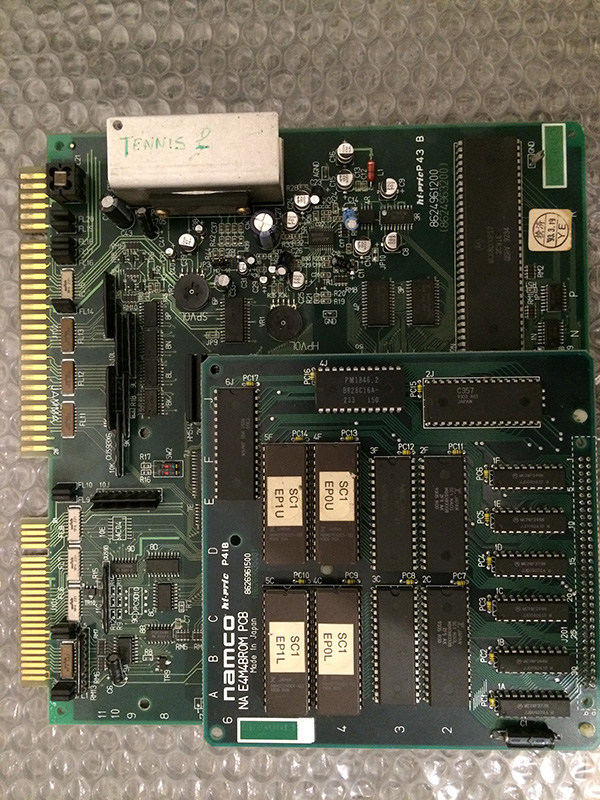
Another pcb which was part of the cheap deal.
It was completely dead. Given that it is not an interesting game I was about to use it for spare parts when I asked my friend Caius if he ever repaired a Namco NA-1
He told me he once repaired one with a capacitor connected to the reset circuit of the 68000 which faulty and didn’t produce the reset signal.
I tested mine and to my surprise the reset was stuck low.
I changed the capacitor smd 22uF @C5 with one 1uF which I had available and the game booted.
Unfortunately the sound was completely missing, so I probed with my portable amplifier some smd capacitors which are know to be leaking very easily and I found one which interrupted the sound to the main ampli.
After changing it, the sound was very low with lot of background noise.
To end a long story short, I recapped many small smd caps with new ones and restored full volume.
This is a common problem with Namco NA-1 pcbs
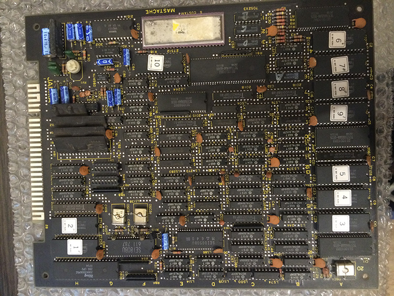
I got this pcb togheter with other games all untested as part of a very cheap deal
When I fired it up, I noticed that it worked except sound.
This game has a rare Toshiba sound cpu T5182 which is an embedded z80 with ram and rom inside the same package.
One trick to know if the problem lies in the sound cpu is to coin the game. If it works, than the cpu, which also handles the coin inputs, is fine.
That was the case with my pcb, so given that I could hear noise from the speakers, I troubleshooted the pre amps with my portable amplifier.
There are two op amps, one is a 4558 directly connected to the Ym3016 DAC, and the other is connected to the 4558, which is an LM324.
The latter had all the outputs dead, so exchanging it with a good one restored the sounds.
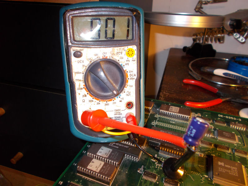
Some days ago I had on the bench this Wolf Fang: Kuhga 2001 PCB (known outside Japan as “Rohga – Armor Force”) , a good-looking horizontally scrolling shoot ’em up manufactured by Data East in the 2001 :
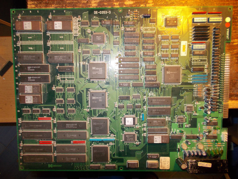
When I powered it up, I was greeted by this screen.

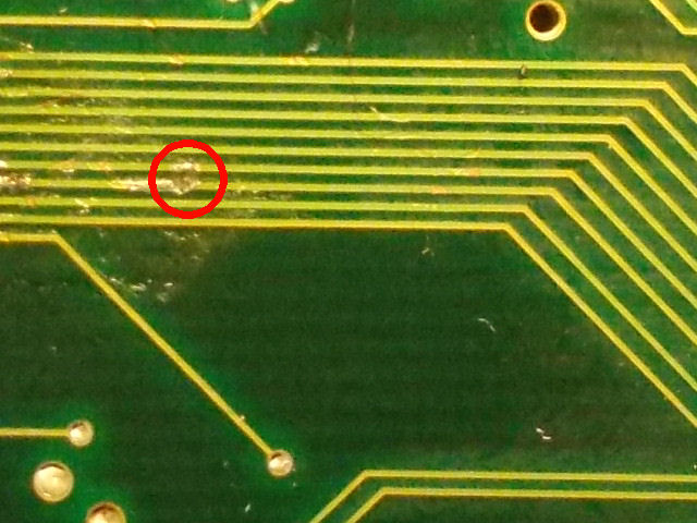
It was a clear lack on SYNC signal confirmed also by a measurement with a frequency counter on pin 13 solderside of the JAMMA connector.So, given the absence of schematics, I started to trace back the signal with a multimeter but couldn’t find where it was generated.Visually inspecting the board I found a suspicious crack over a trace :
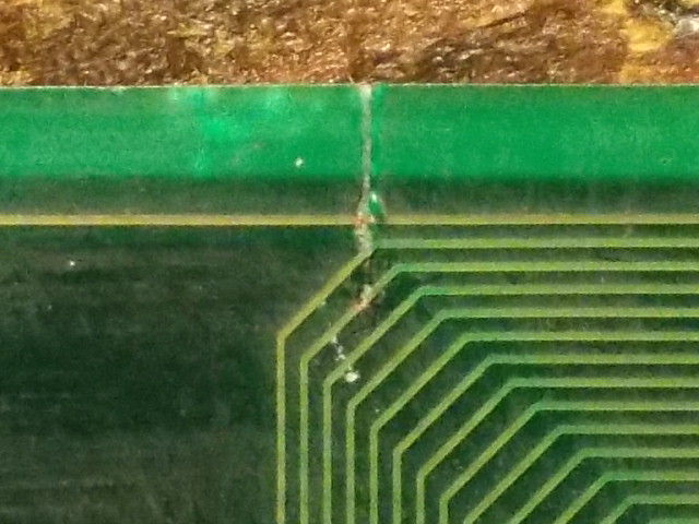
My multimeter confirmed the trace was really severed.After patching it, the SYNC signal was restored but there were jailbairs on the sprites:
![]()
Sprites are stored in some 42 pin MASK ROMs :
![]()
I visually inspected the area and found another broken trace on solderside which lead to a data line of these MASK ROMs:
I promptly patched it with some AWG30 wire:
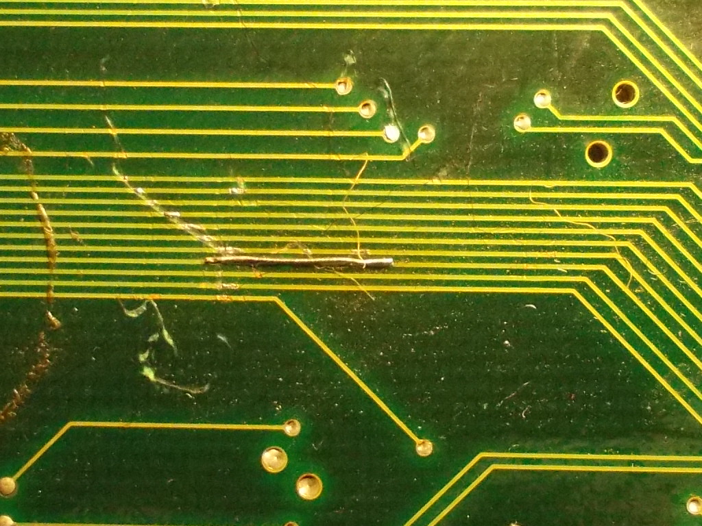
and sprites were restored:
![]()
But after this I realized that sound was missing at all.Diverting the audio signal to an external amplifier, I could hear both music and sounf FXs but there was no output from the TA8205AH amplifier on PCB :
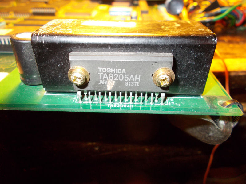
So I decided to remove and replace it but , as for my previous Pitfall II repair, I was wrong, it was good.Looking at its datasheet, I could figured out how its mute circuit was made:
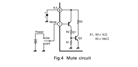
Checking the 220uF 16V electrolytic capacitor connected to pin 8 of the amplifier gave me a dead short across the terminals.So I desoldered and test it out of circuit having confirm it was really shorted:
Replacing it restored full sound.End of job.