This repair log is proof that we must always start from the simpliest things!
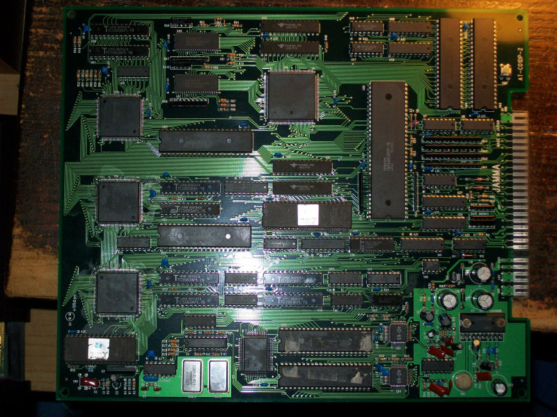
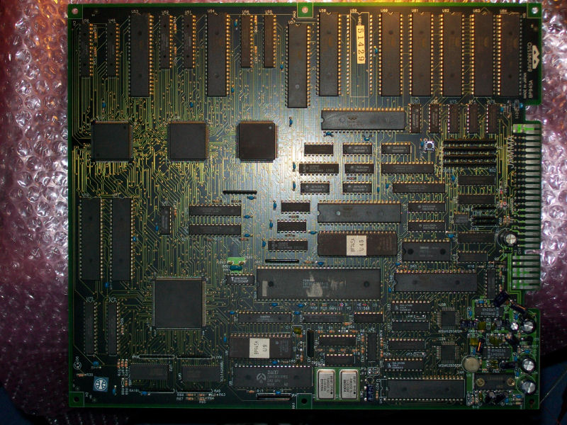
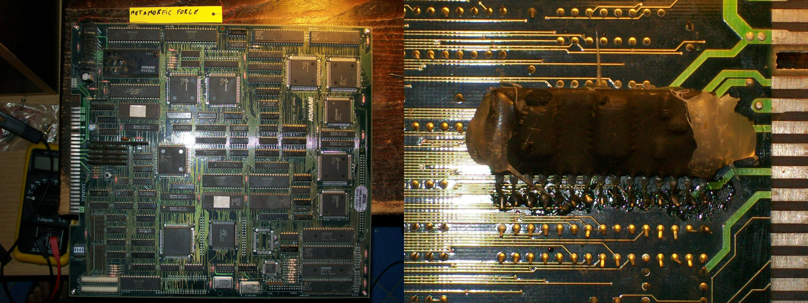
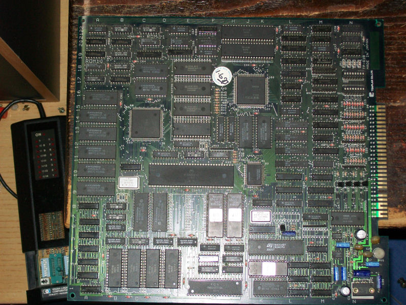
Another faulty board from my friend ‘mastercello’, this time an original Toaplan Out Zone :
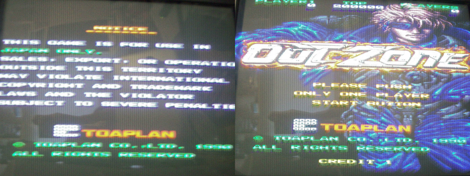
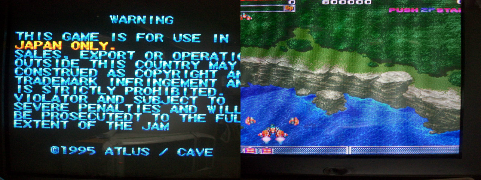
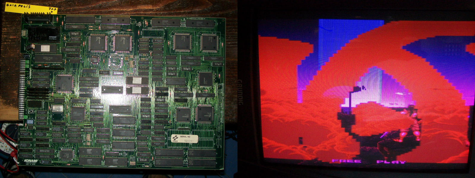
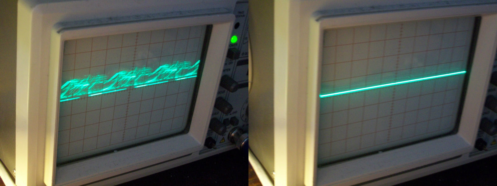
He told me that it worked once and then nothing.Actually when I first powered it up I got this :
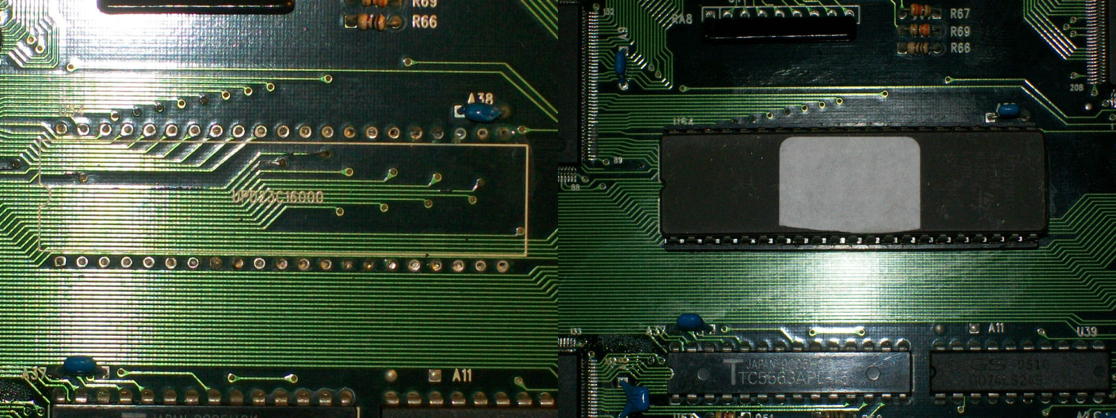
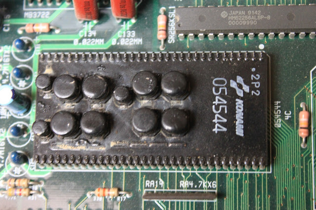
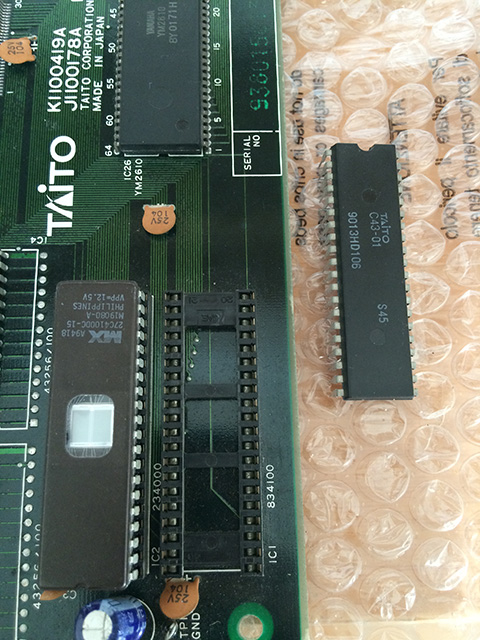
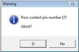
The screen with the wavy lines is common on all the Toaplan PCBs which run on similar hardware.It means that the system is being intialized but it should last until the CPU starts to properly execute code.In my case this screen was permanent so there had to be a problem in the main code execution.First thing I did was to check CLOCK, /RESET and /HALT lines of 68000 main CPU, they were fine.Then I dumped the two 27C010 programs ROMs and got from my programmer a warning about a poor contact on pin 17 (which is a DATA output) of the one labeled ‘TP018_08’:
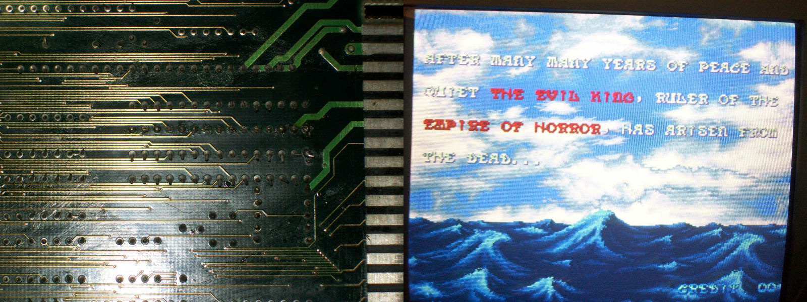
A closer inspection of the device revealed many oxidixed pins.A bit of fine sandpapering is what the EPROM device needed and enough to fix the board completely.