Nintendo VS System repair log #1

 PCB Repair Logs  Comments Off on Nintendo VS System repair log #1
Jun 302016
 

In the past days I received this Nintendo VS. System for a repair:

DSCN3625

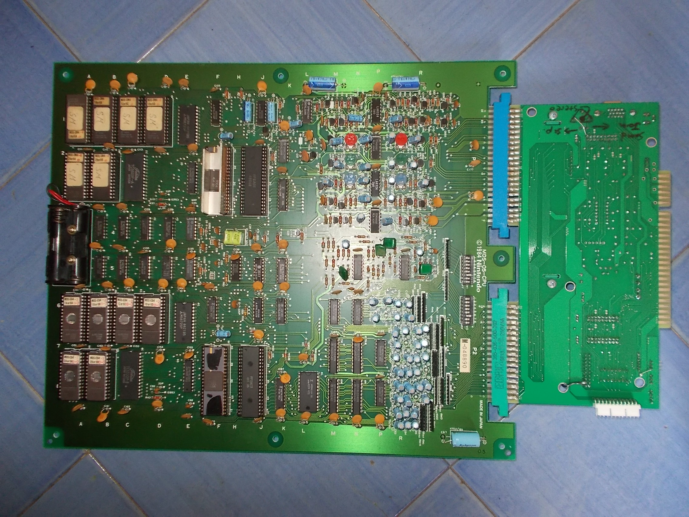
For the uninitiated the Nintendo VS. System is an arcade platform designed for two-player competitive play using the VS. UniSystem or VS. DualSystem based on the Nintendo Entertainment System.

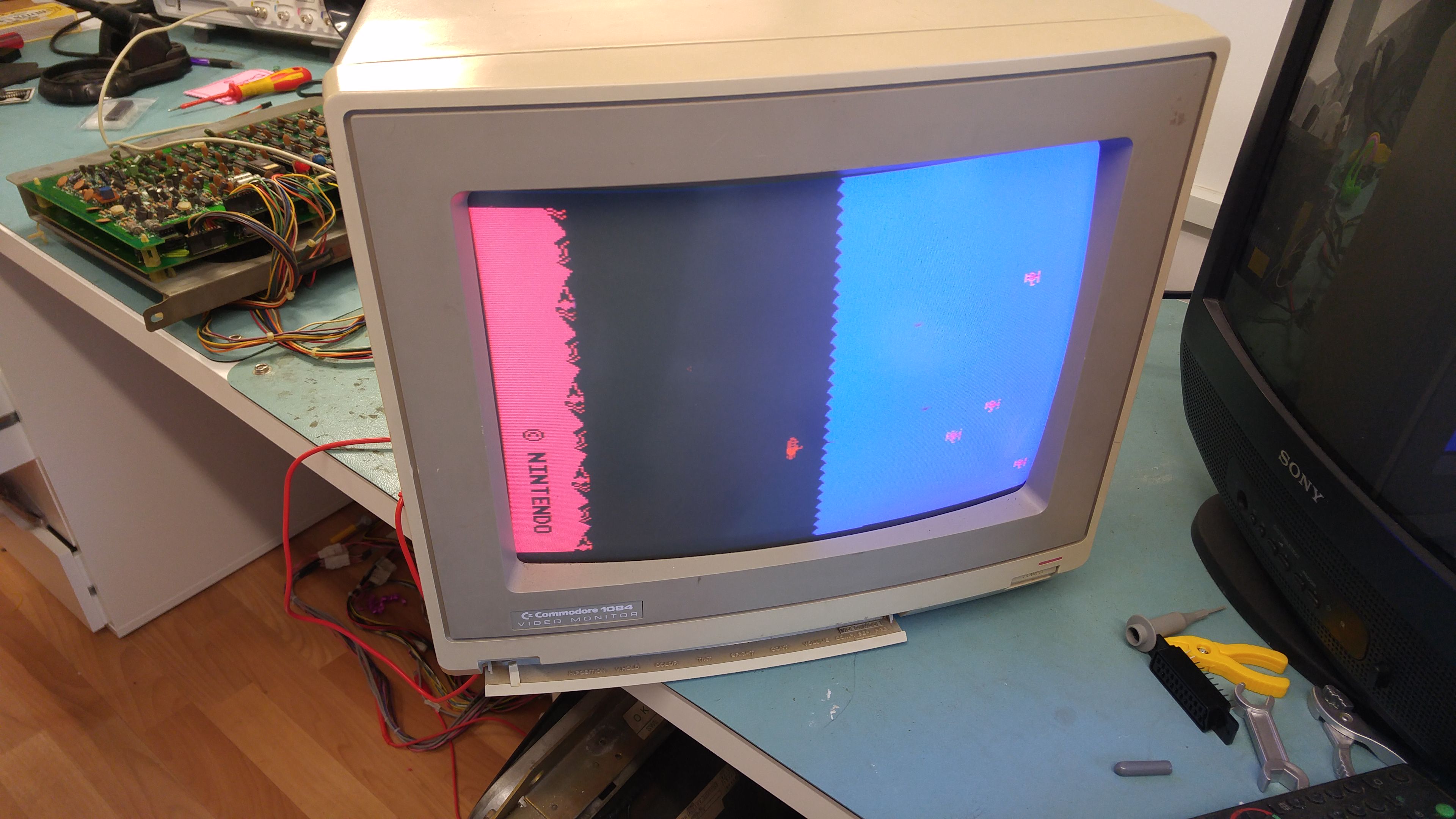
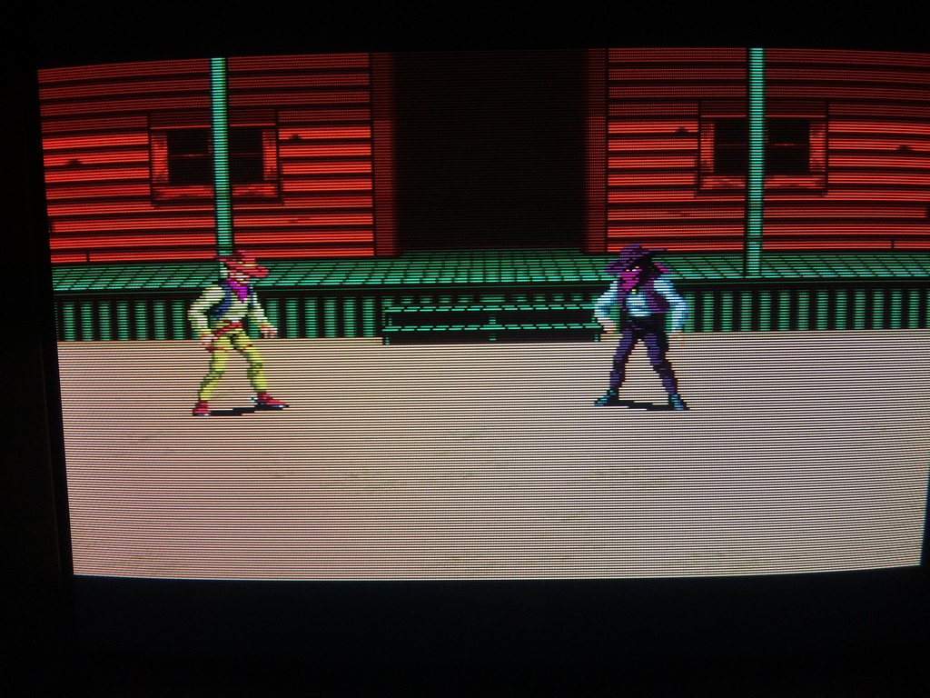
The system came with his special JAMMA adapter and two game ROM sets installed (Super Mario Bros and Excitebike) so time to power it up and I got this scenario:

wrong_colors

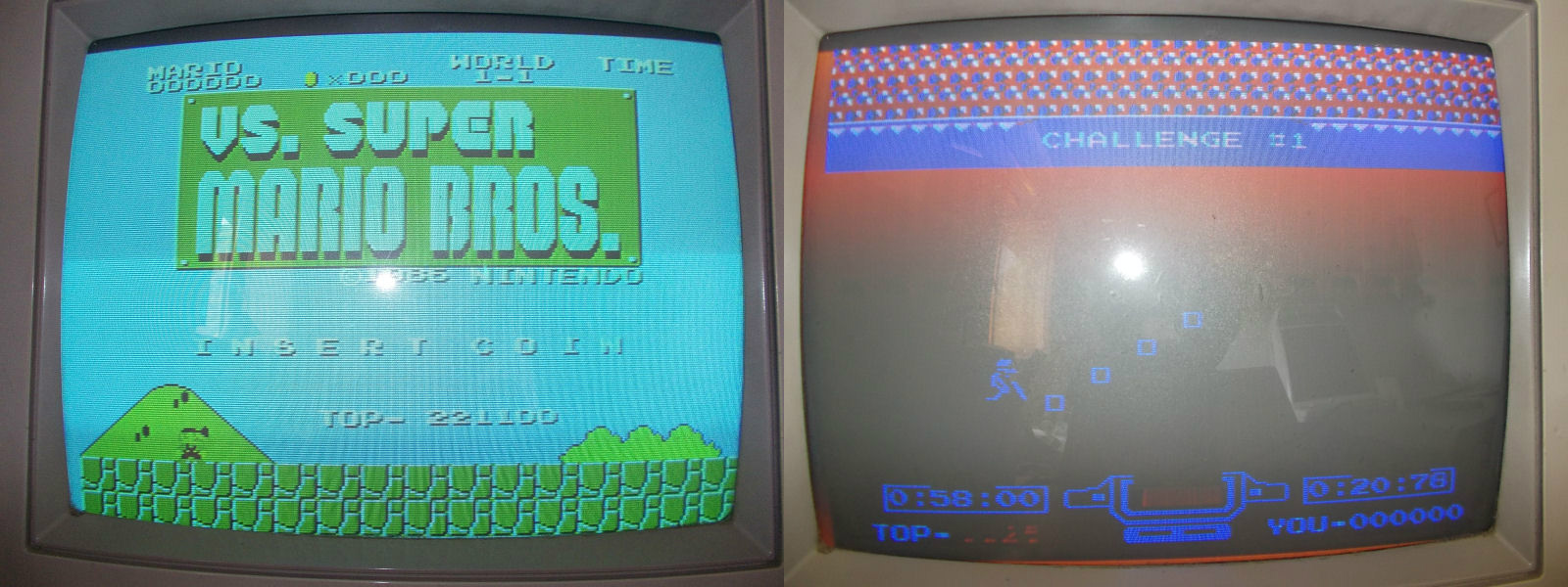
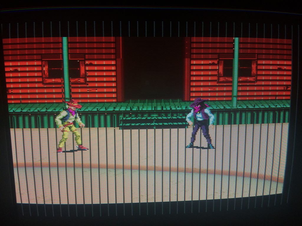
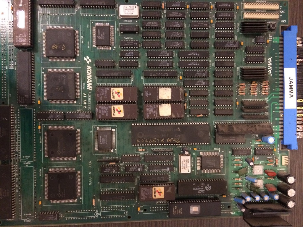
As you can see, screen was all bluish sign that the RED component was missing.This was confirmed by probing the signal, it was stuck LOW on its source which is pin 14 of the RP2C04 PPU @8F :

RED_PIN14_RP2C04

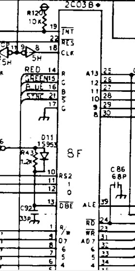
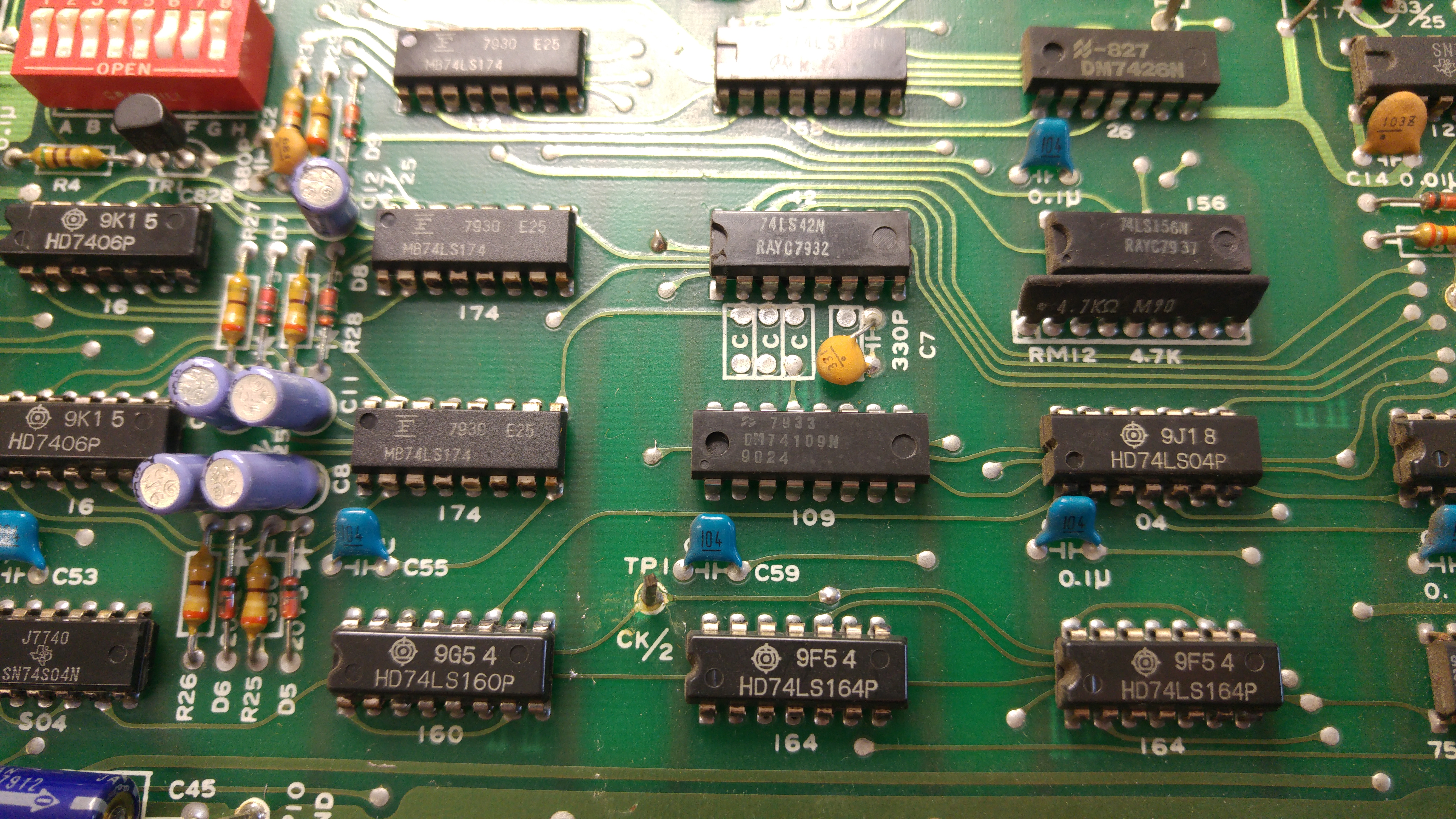
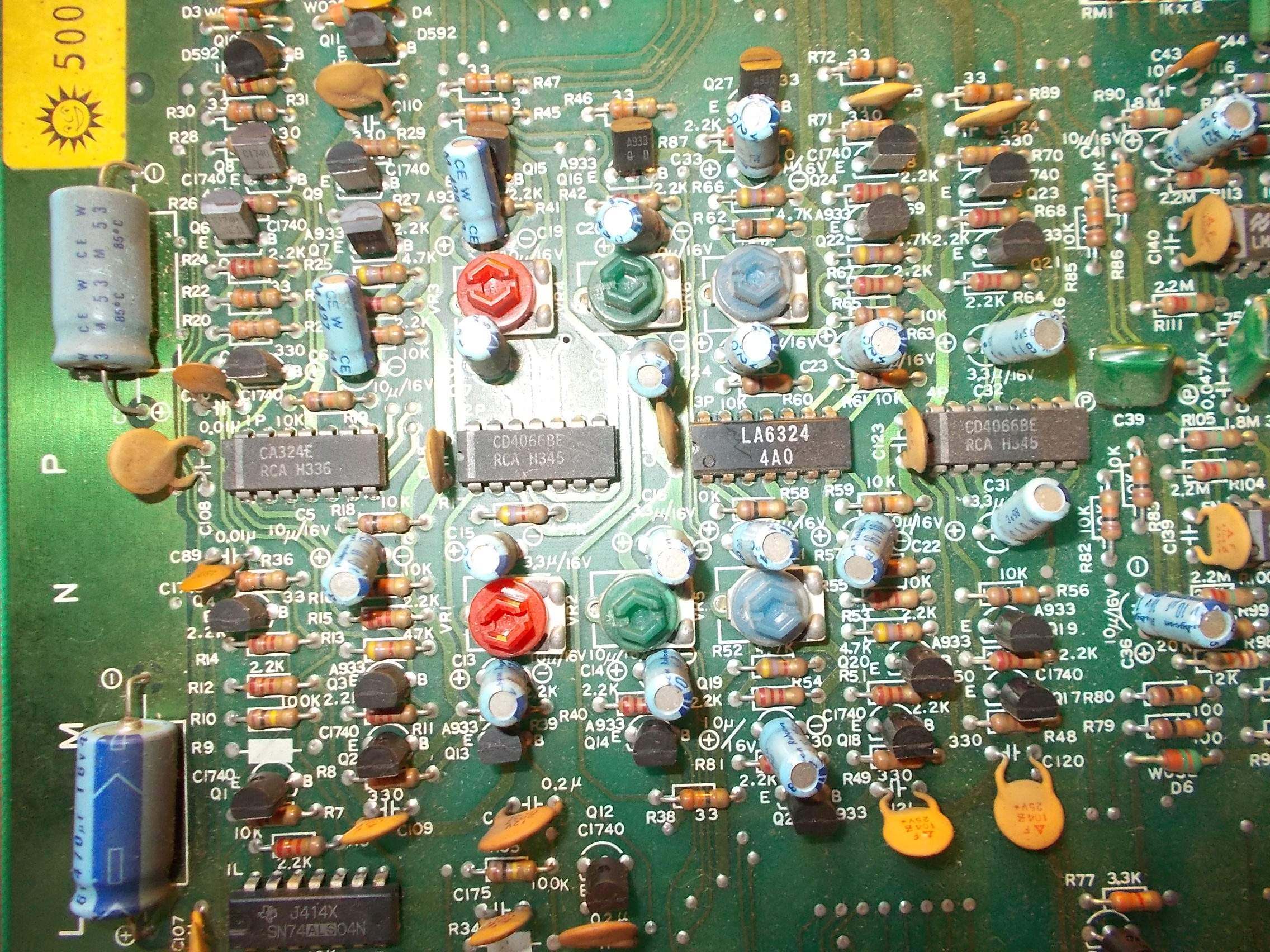
The PPU chip was tested as good in another system so there was something in the path which forced the signal LOW.Before reaching the corresponding pin on edge connector, the signal is converted from digital to analog by a net of resistors and amplfied by a LM324 OP-AMP @1P:

RED_circuitry

DSCN3632

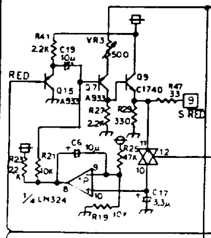
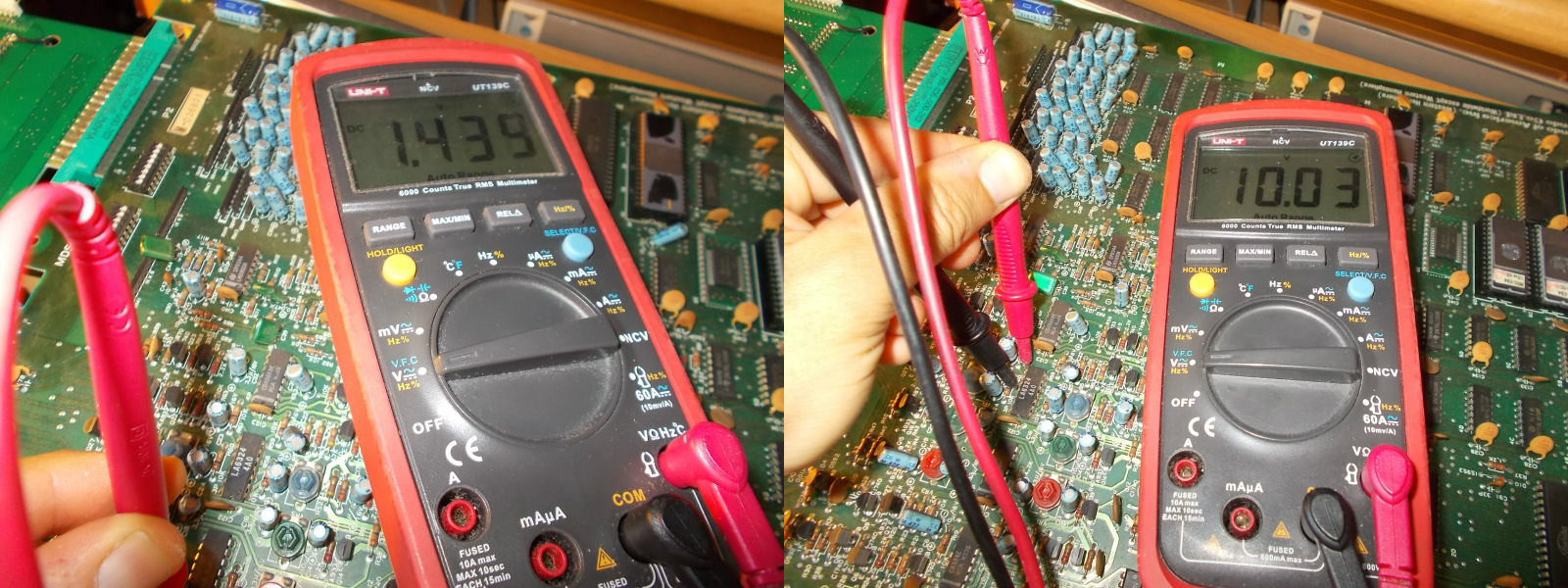
Probing the output pin 8 of this OP-AMP I could measure only +1.4VDC against +10VDC of the output of the other one @3F which is involved in the blue color (which was correctly working)

OUTPUT_LM324@1P_@3F

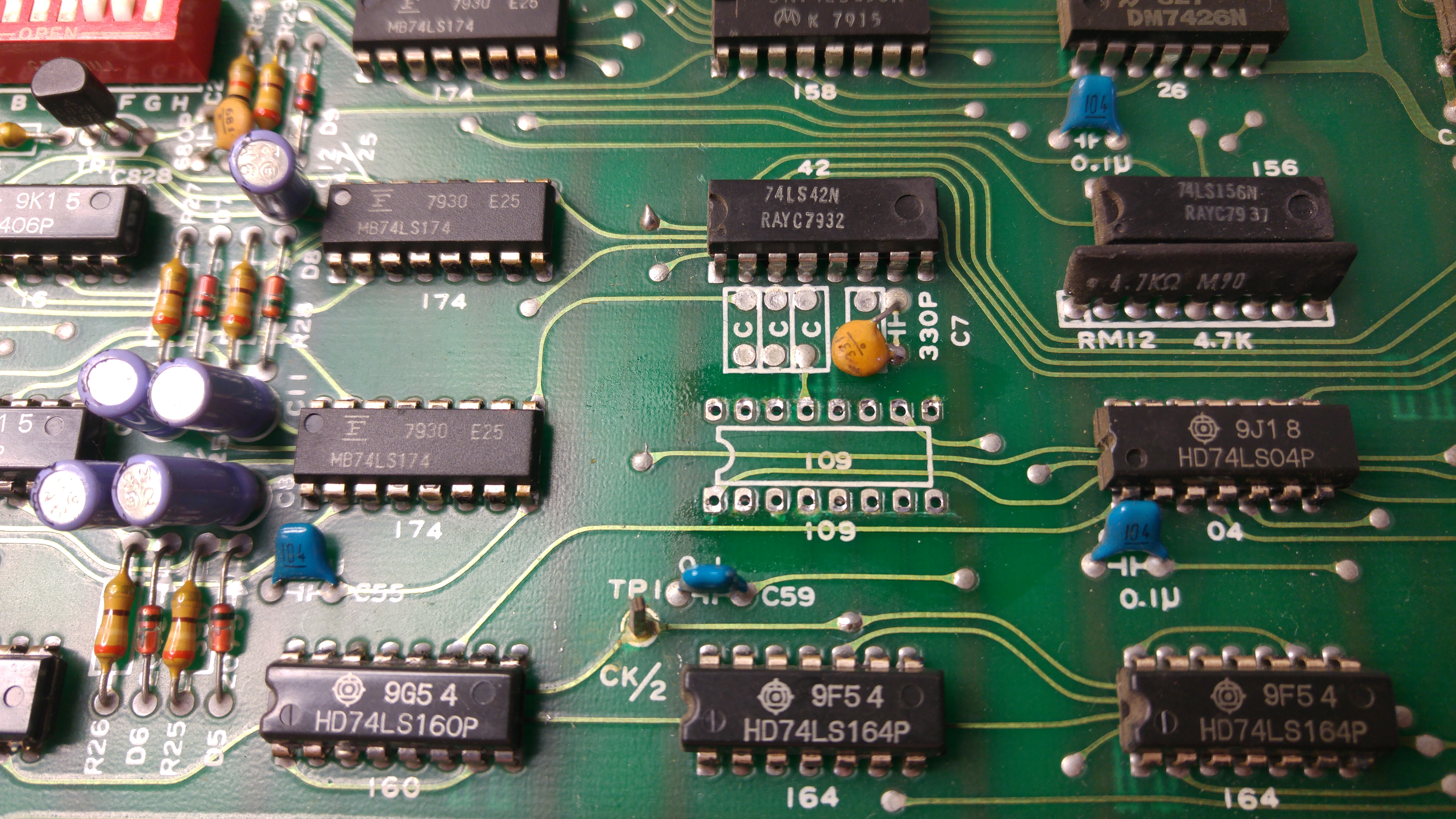
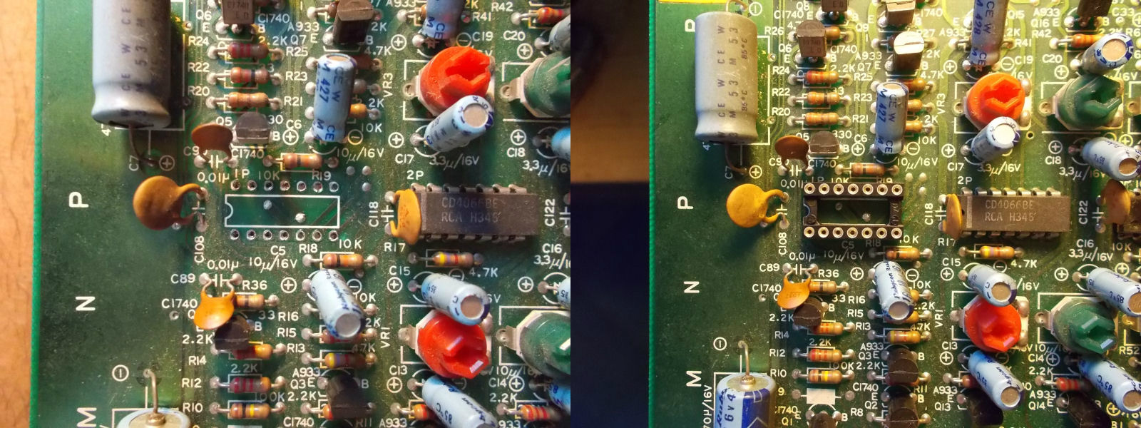
So I decided to pull out the LM324 and add a rounded machine-tooled socket :

LM324@1P_reworking

When tested out-of-circuit, it failed:
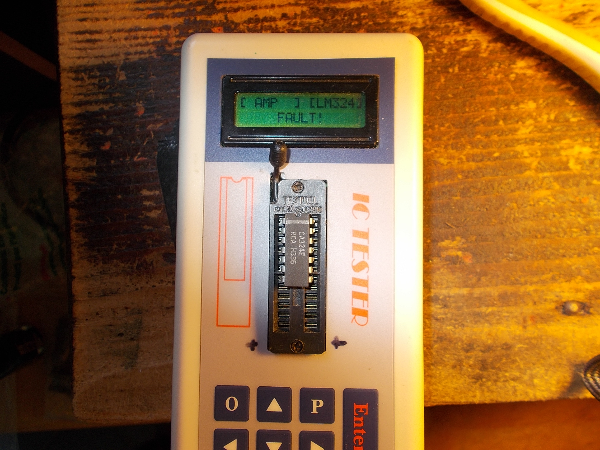
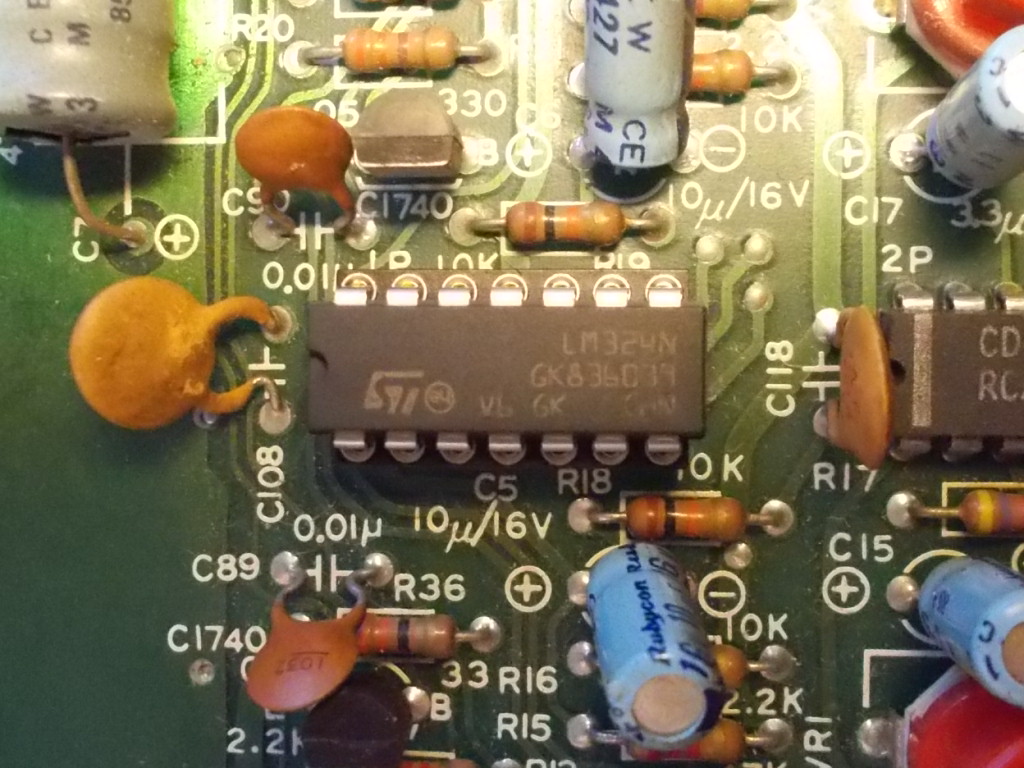
DSCN3635

Fitted a new one:

new_LM324_fitted

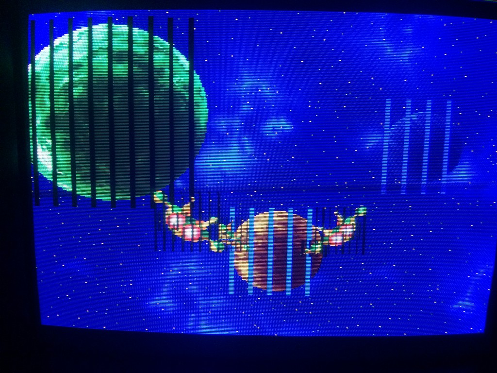
and red color was restored :

fixed

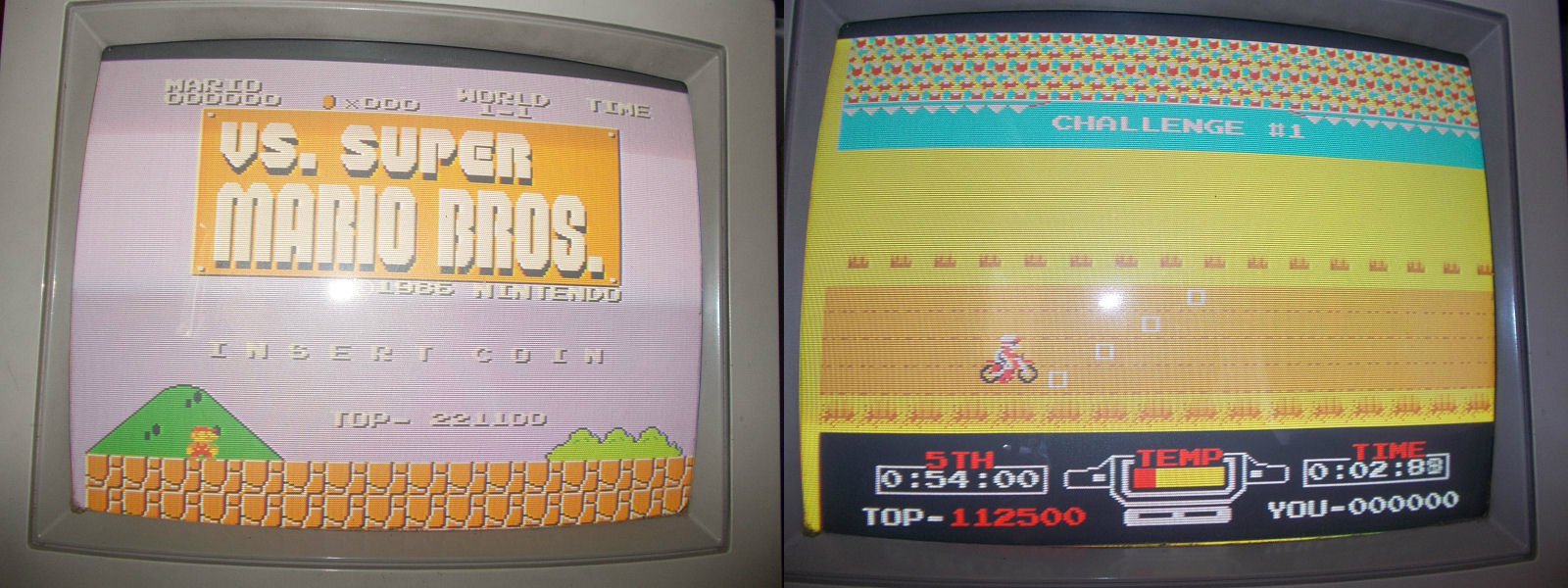
No further issue were found so board 100% working.End of job.

 Posted by at 3:37 pm

Tecmo Knight repair log #2

 PCB Repair Logs  Comments Off on Tecmo Knight repair log #2
Jun 252016
 

Dug this board out today with the view of selling it.
I put it on to test and also fired up MAME for a comparison and noticed that the digital samples weren’t playing at all. It first noticeable on the attract sequence when the lightning strike and you should be able to hear thunder.
This game uses an M6295 chip in order to deal with the samples so it was really easy to make a start trouble shooting. Using the scope I could see all the inputs and outputs were toggling when I would expect and could see one of the enable lines going active when the thunder sample was meant to play but the DAO pin (pin 36) was just dead. I did try to reflow this just in case but it made no difference.
I replaced this with one from a scrap PCB
20160625_190328
20160625_193803

Sounds are all back now

 Posted by at 8:00 pm

Nintendo Helifire repair log

 PCB Repair Logs  Comments Off on Nintendo Helifire repair log
Jun 232016
 

Got Muddymusic’s Helifire (not to be confused with Hellfire by Toaplan) to look at.
He bought the original cocktail cab and on first power up was met with nothing but a “loud noise”.
His initial checks were that his +5v line was reading +2.5v and sent me the PSU to work on.
Now due to the various AC voltages required to actually use the PSU I was unable to do any real testing so instead he sent me the transformer and PCB too.
Now I could start checking the PSU I found that the +5v line was indeed around +2.5v. While I had the PSU powered up I suddenly got a +5v voltage output and it was pretty solid.
I couldn’t check to see if the game was running at this point as I had no way to connect the game to a monitor so I probed the video out pins with the scope and everything appeared to be at least what I expected.
While I had the PCB hooked up to load the PSU I momentarily saw the voltage on the +5v line would drop to +2.5v and then to my horror rose up to +8v!
I immediately powered it down and it has not been back on since.

I opted to hook it up to a switcher but when I did I noticed the video sync output was missing. I guess the PSU took it out. I also noticed the 8080 CPU wasn’t running either and was getting quite hot.
I’ve got access to a thermal camera right now so checking the PCB with that revealed the 8080 in the top right corner was way too hot.
flir_20160609T191950

I had no spare 8080 CPU’s so placed an order for a couple and moved onto the missing SYNC signal.

Working backwards from the SYNC output and using the schematics available I quickly found the 74LS109 at location 3B had stuck outputs despite having good inputs and a healthy clock signal.
helifire-clock
hf_109

20160611_114541

Replacing this chip gave me back my signals.

A week later my 8080 CPU’s arrived and I managed to get the video output hooked up to my Commodore 1084D monitor to test.
At the time I didn’t even realise that the game was black and white and uses a colour overlay so I was initially confused by the colour in the game but Muddymusic soon put me right on that.
IMG-20160622-WA0009

 Posted by at 7:45 pm

Bucky O’ Hare repair log #2

 PCB Repair Logs, Repair Logs  Comments Off on Bucky O’ Hare repair log #2
Jun 182016
 

Got another Konami game with the usual jail bars defect that is so common on these games

bucky3


I ran again the maskrom test and it reported bad maskrom 8B.

After desoldering it and testing as 27c160, the programmer complained about missing contacts on several pins.

bucky

After replacing the markrom with a 27c160, the game was 100% fixed

bucky2


bucky4

Sunset Riders repair log #4

 PCB Repair Logs, Repair Logs  Comments Off on Sunset Riders repair log #4
Jun 182016
 

I got this pcb for a repair.

Gameplay was fine but graphics had black lines and music had a lot of white noise.

ssrider


I ran the maskrom check and it reported two roms as bad, one of which was infact the rom with the sound data.


ssrider2


It doesn’t mean necessarily that the maskroms are bad, can be also that the custom chips have some pins not soldered correctly or the chips themselves being faulty.

The only way is to desolder the maskroms and check on a programmer if it reports pins not connected which means that the chip internally is broken.

After a check with the romset, I decided to dump rom 16k as 27c400 (4mbit eprom with maskrom pinout) and rom 1d as a 27c800 (8mbit 16bit eprom).

Both were reported as having pins non connected properly.

ssrider3

So I replaced maskrom 16k with a 27c400 and the markrom at 1d with a 27c160 eprom (16mbit 16bit eprom) after having doubled the original file in order to prevent the game to access the empty space in case the additional addrr line is not connected to GND or 5V.

This fixed 100% the game

ssrider4

ssrider5