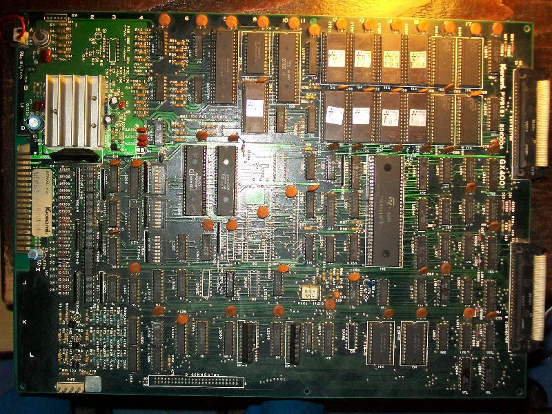
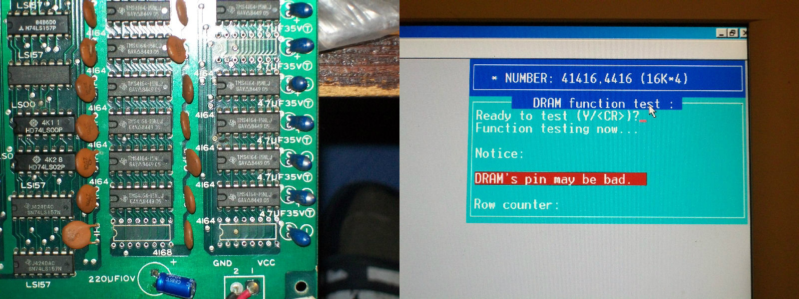
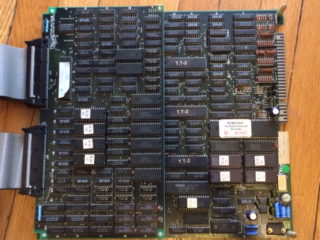
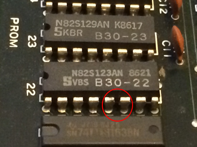
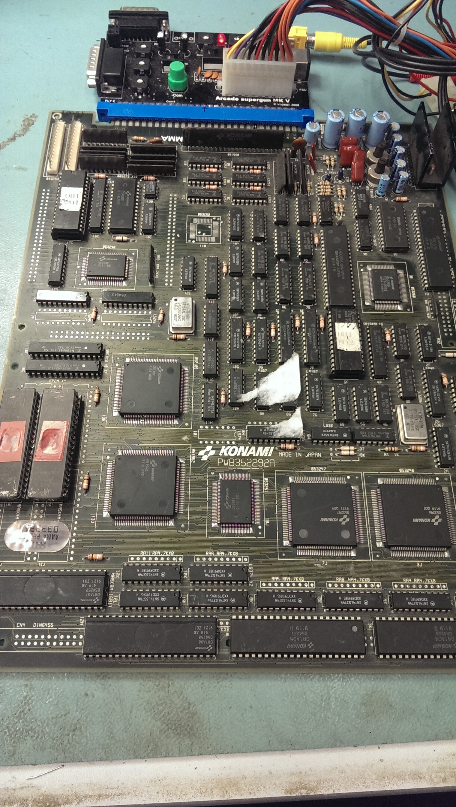
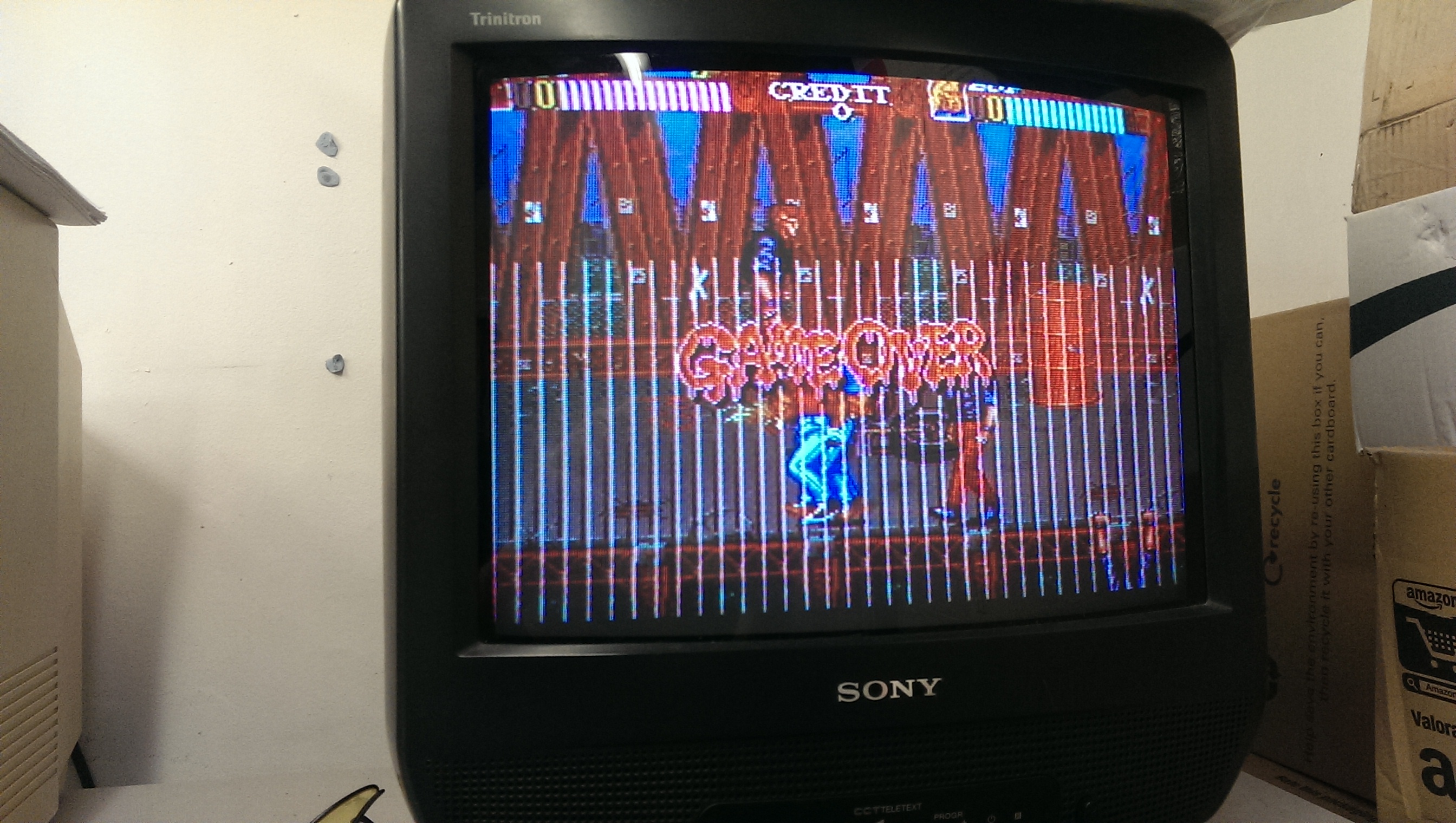
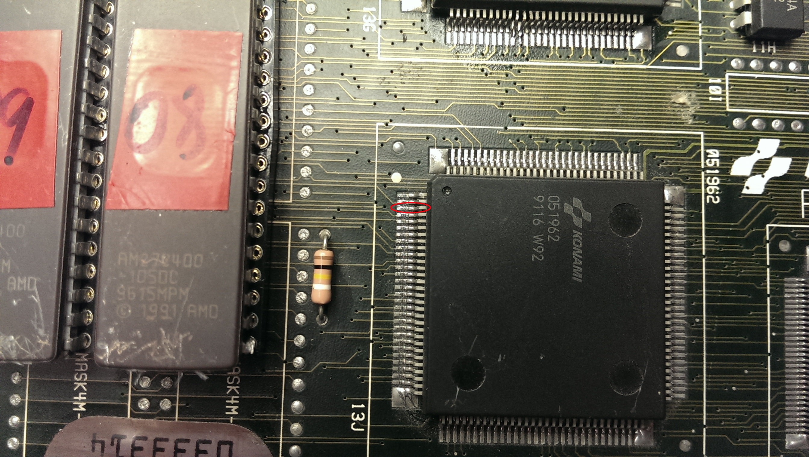
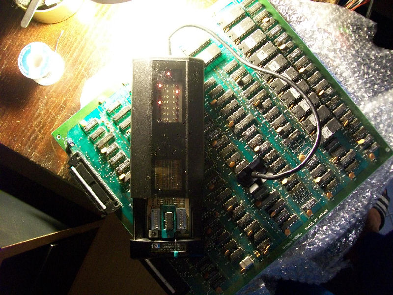
I had this PCB since many years, honestly I couldn’t remember when I got it or where.The only sure thing is that it was faulty.Condition was pretty good for a such ‘aged’ board but it was missing a BPROM @IC101 as you can see:
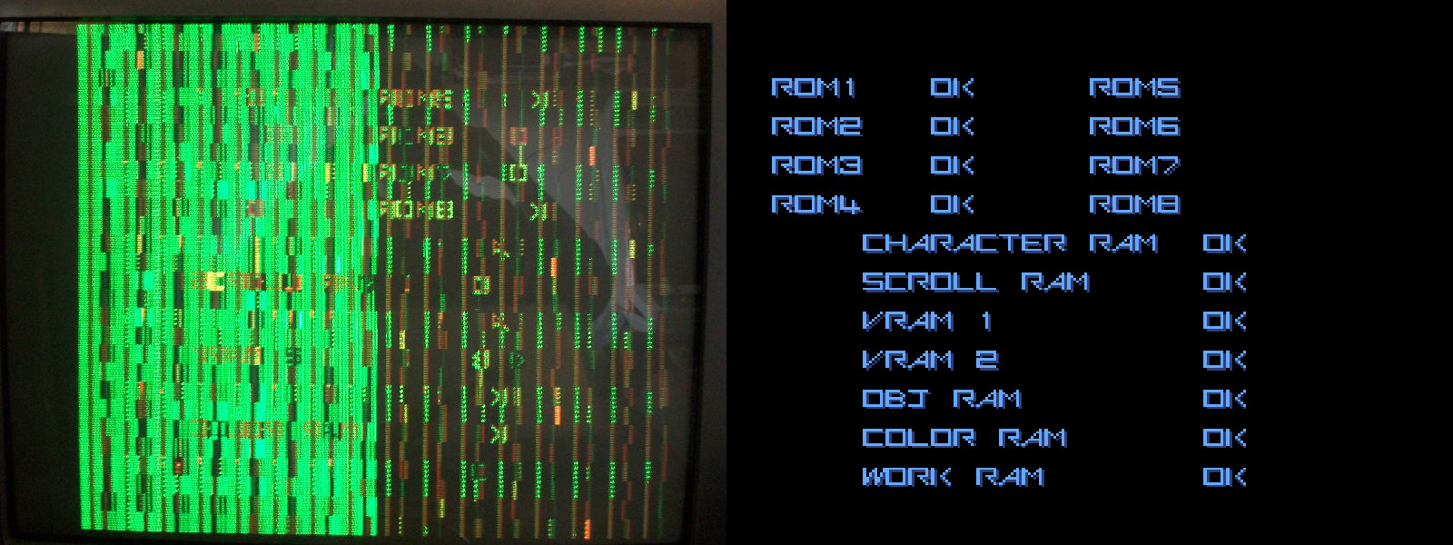
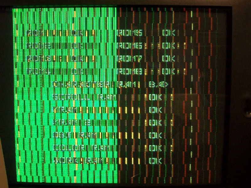
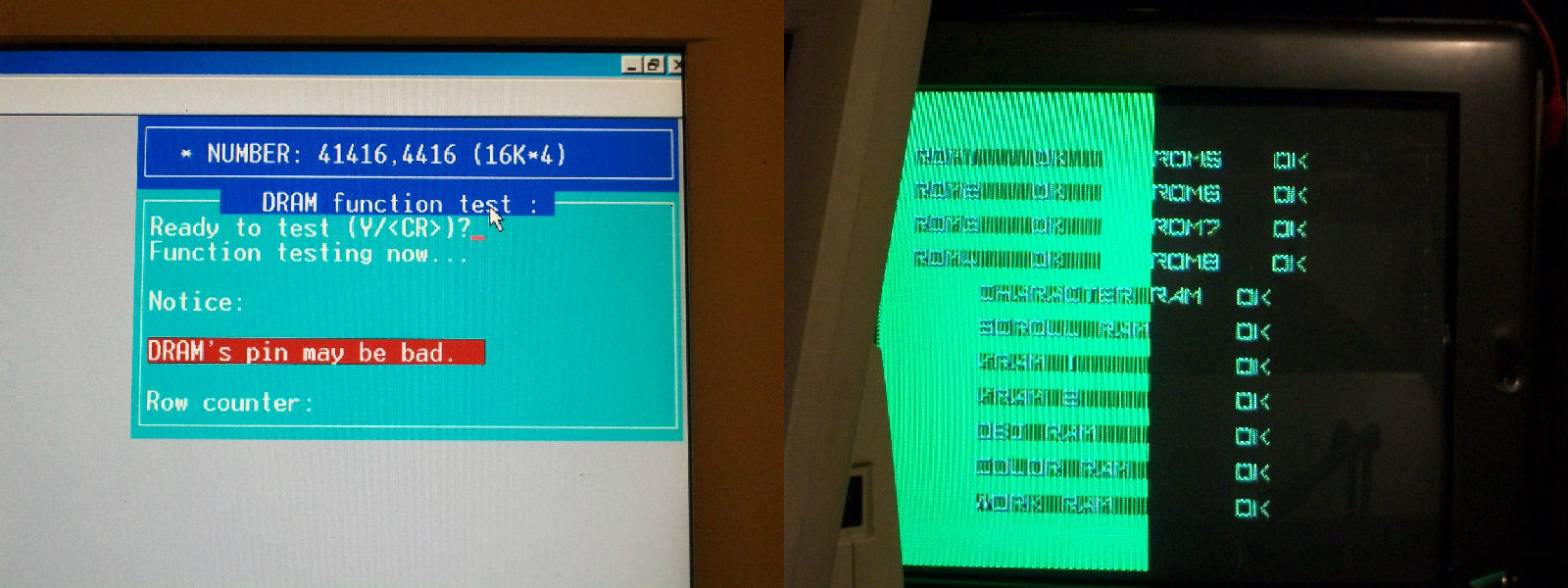
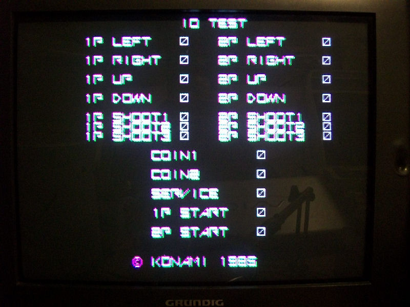
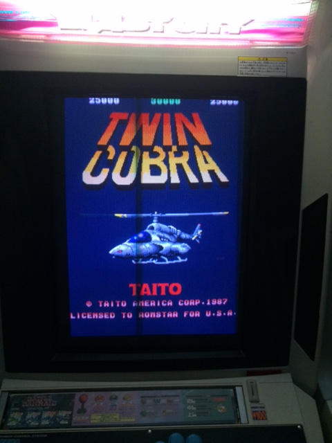
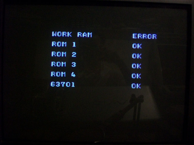
Original part is a Fujitsu MB7114, pretty impossible to find nowadays so I opted for a 82S129 which an equivalent one.After burned the device with the correct file supplied by MAME, I powered on the board and some times it got stuck on RAM/ROM TEST showing error on WORK RAM:
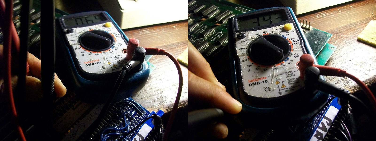
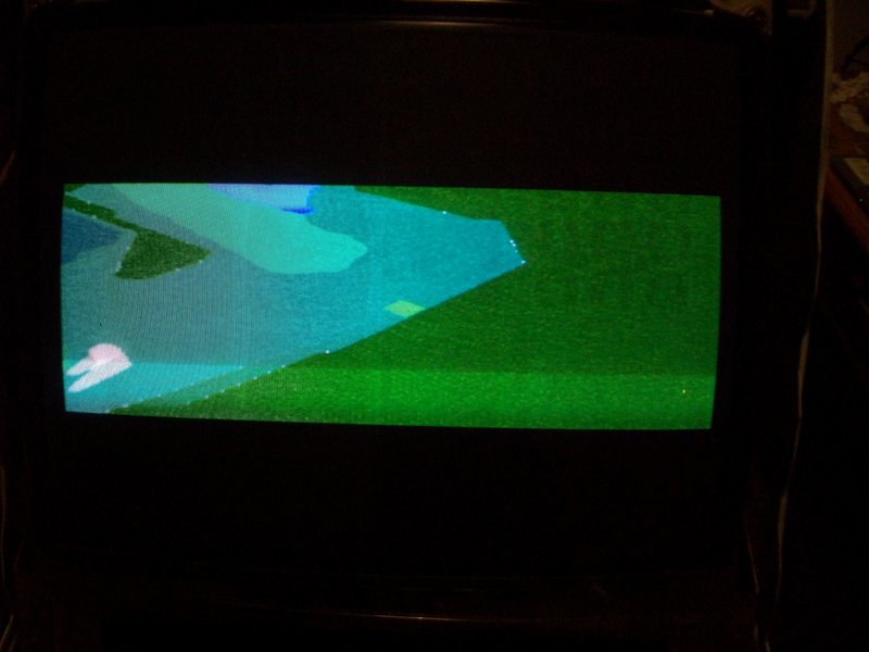
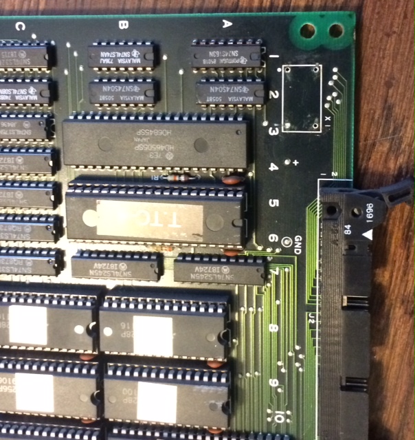
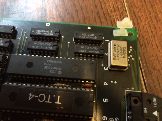
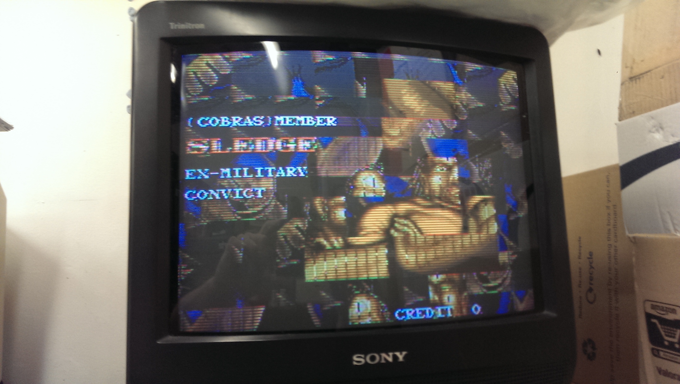
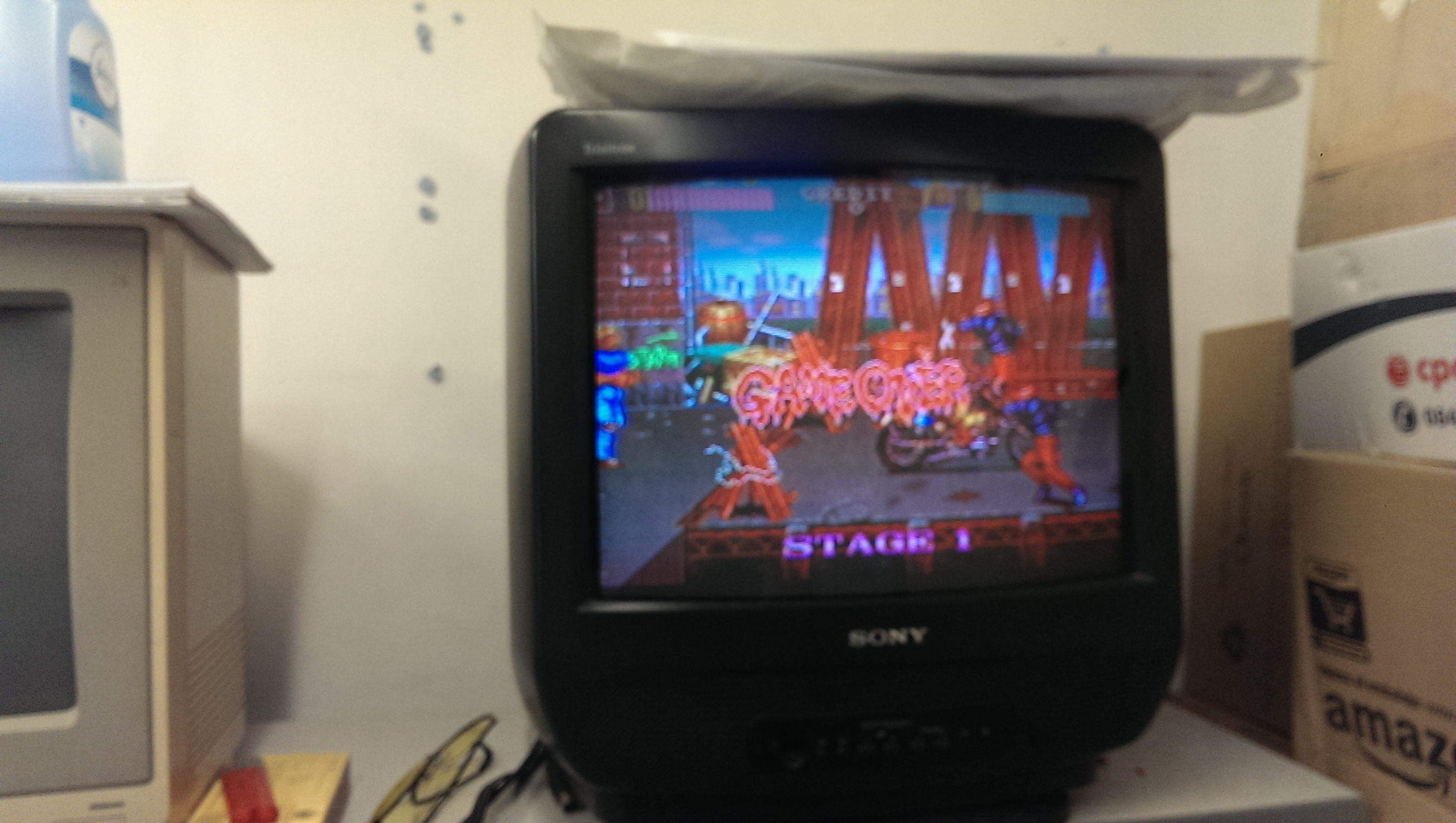
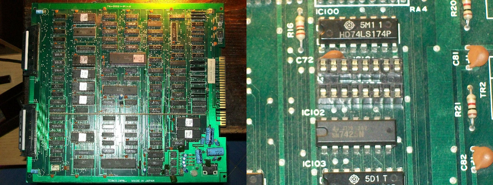
Other times it booted into game but sprites were missing, could not coin up, screen was unstable and speed was kinda accelerated.When I got this strange behaviours, the fist thing I check is the main CPU, in this case an Hitachi HD63C09.Probing it I found that PIN2 and PIN4 were stuck LOW, they are respectively the NMI and FIRQ interrupt lines:
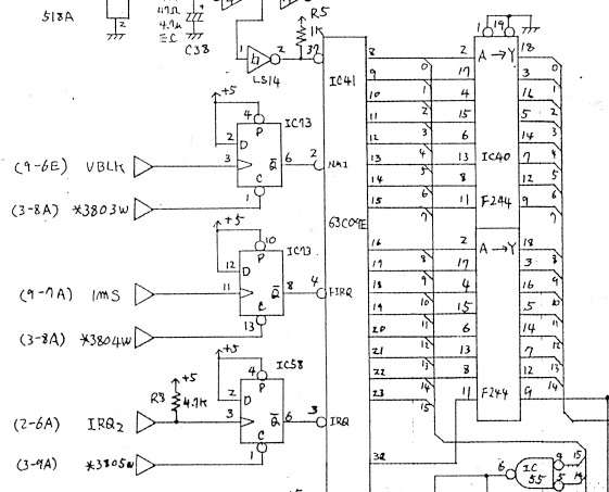
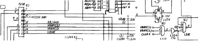
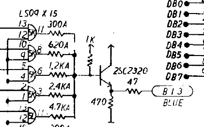
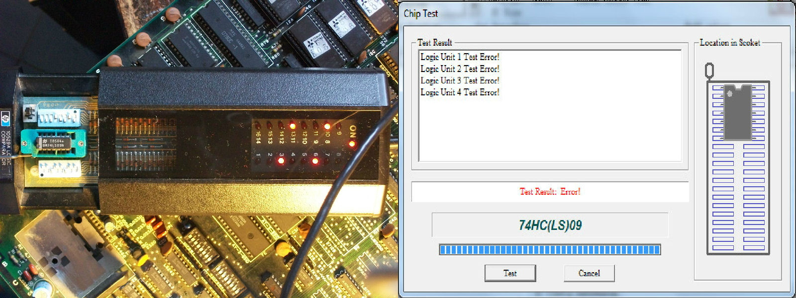
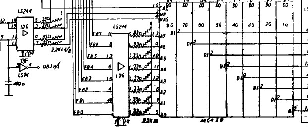
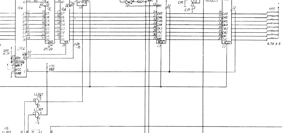
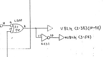
So this meant that CPU was undergoing a request of interrupt from external devices (an interrupt is a signal to the processor emitted by hardware or software indicating an event that needs immediate attention).As you can see from the above schematics these two signals are generated by a 74LS74 @IC73 so for first I went to check it and I found missing CLOCK and CLEAR signals input on PIN3 and PIN13 respectively.In particular CLOCK on PIN3 is the VBLANK signal and this is generated by a NAND gate of a 74LS00@IC70 on VIDEO board :
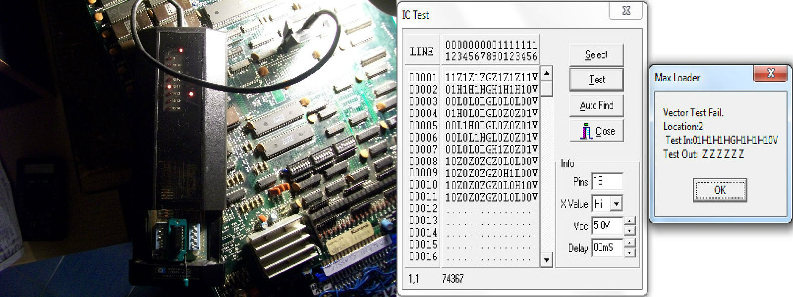
Comparing it in-circuit revealed it was faulty:
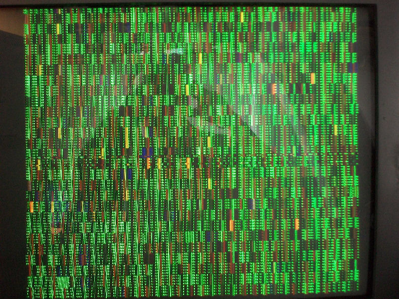
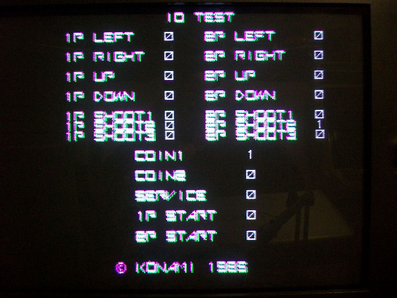
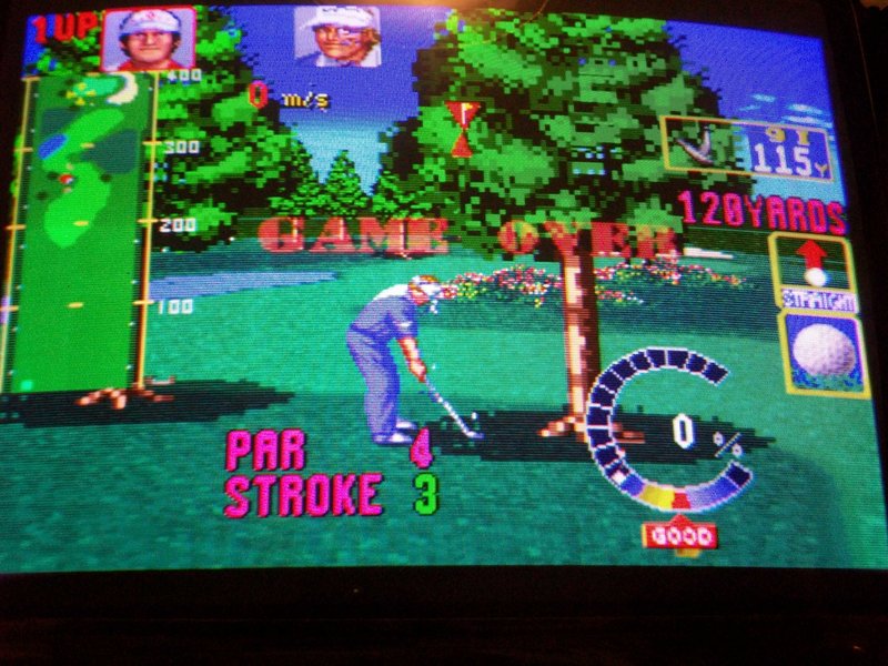
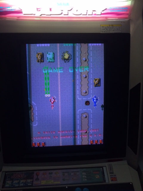
Once replaced it I got no more WORK RAM error and strange behaviours, game was playable but all sprites were missing:
![]()
This a common fault on all Double Dragon PCBs since object generation circuit is wide and made of many components (it occupies five sheets of the .PDF schematics).
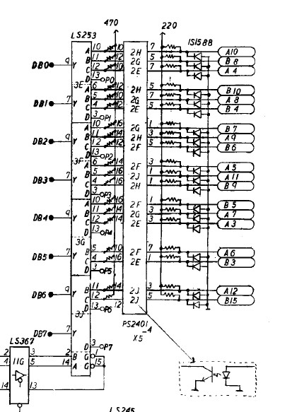
So, following the schematics I checked this part of circuit and all was fine until I came across to this section:
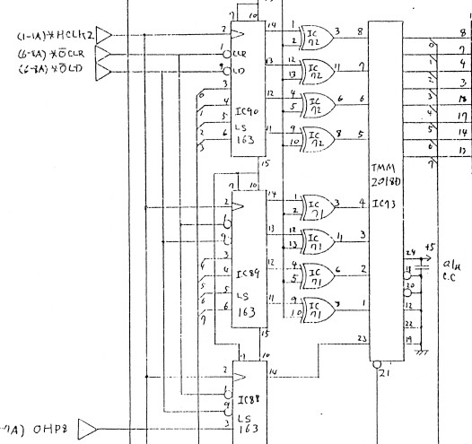
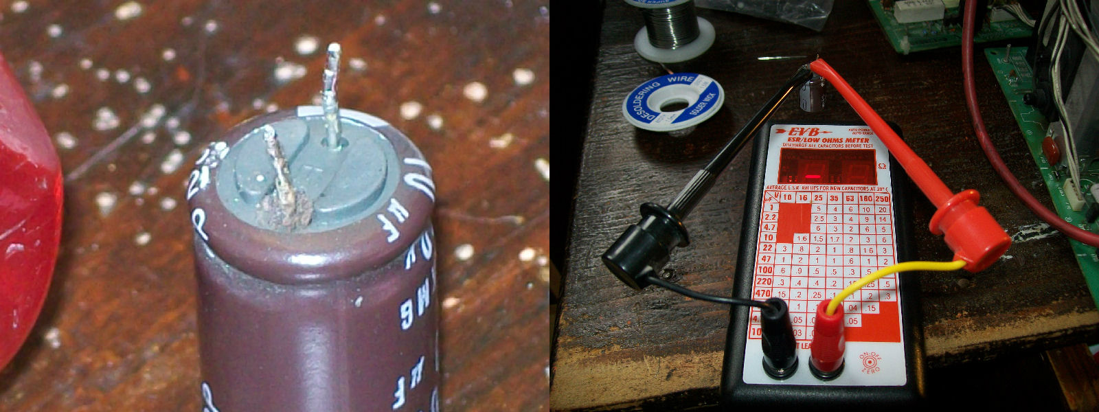
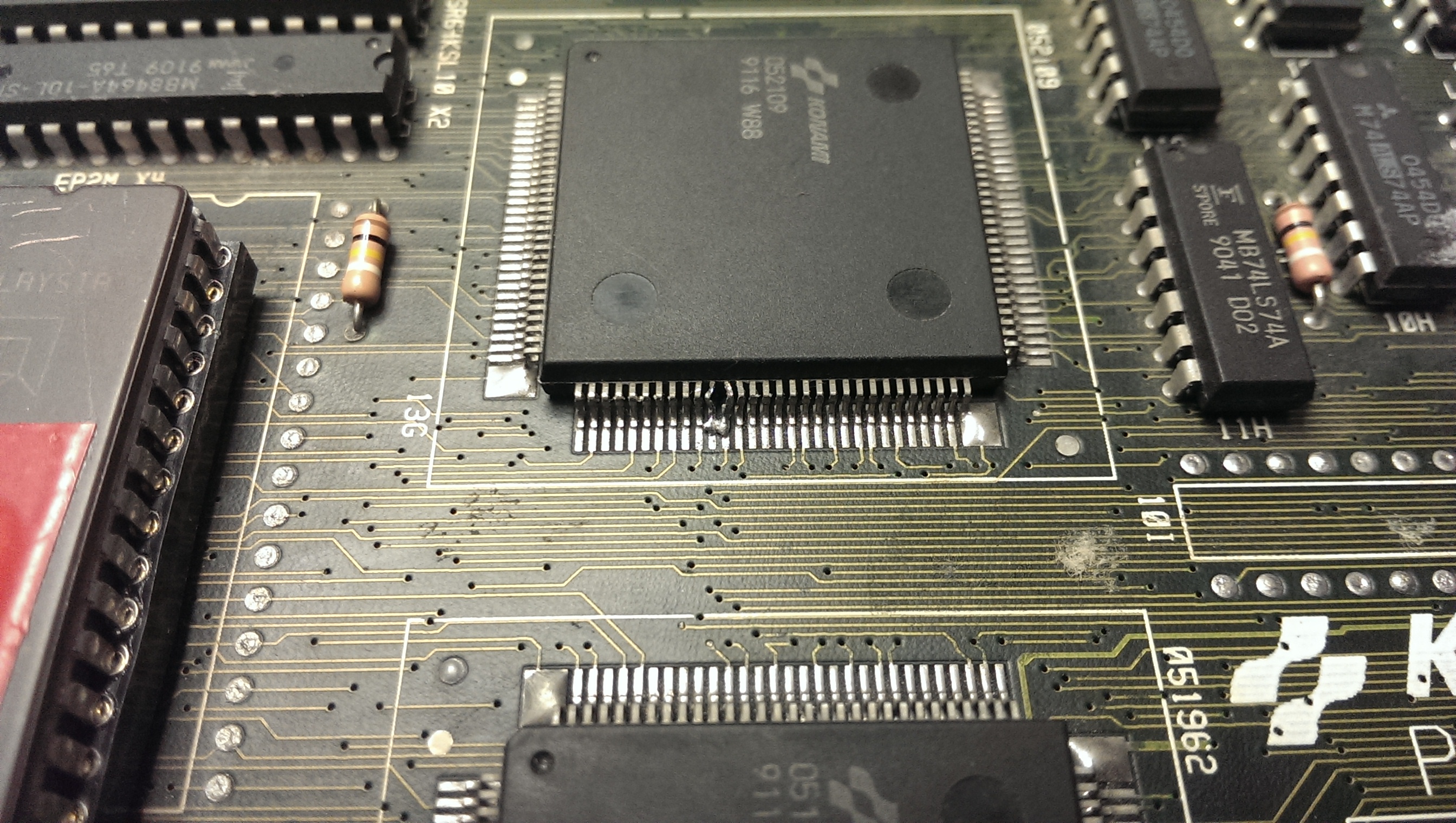
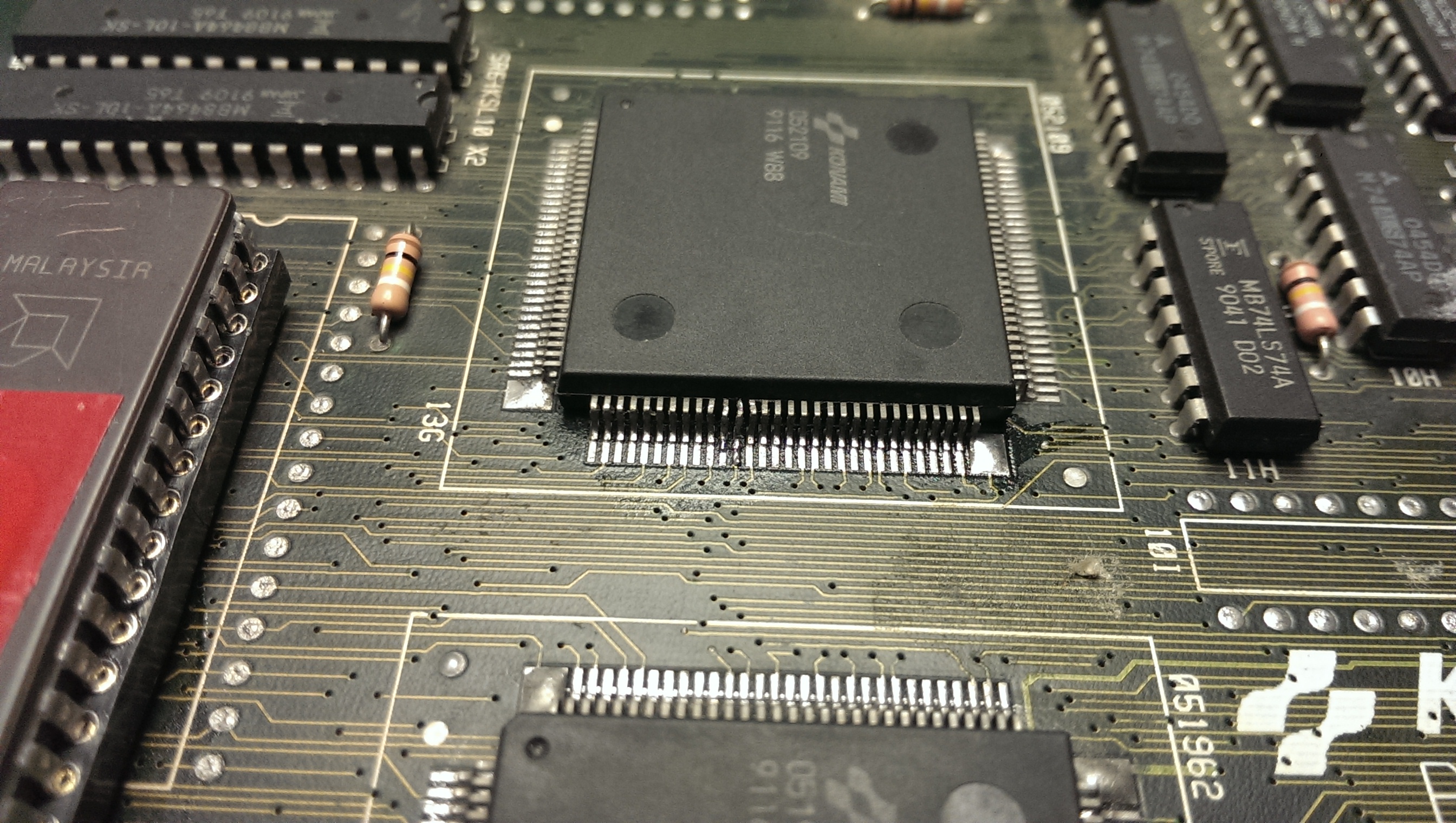
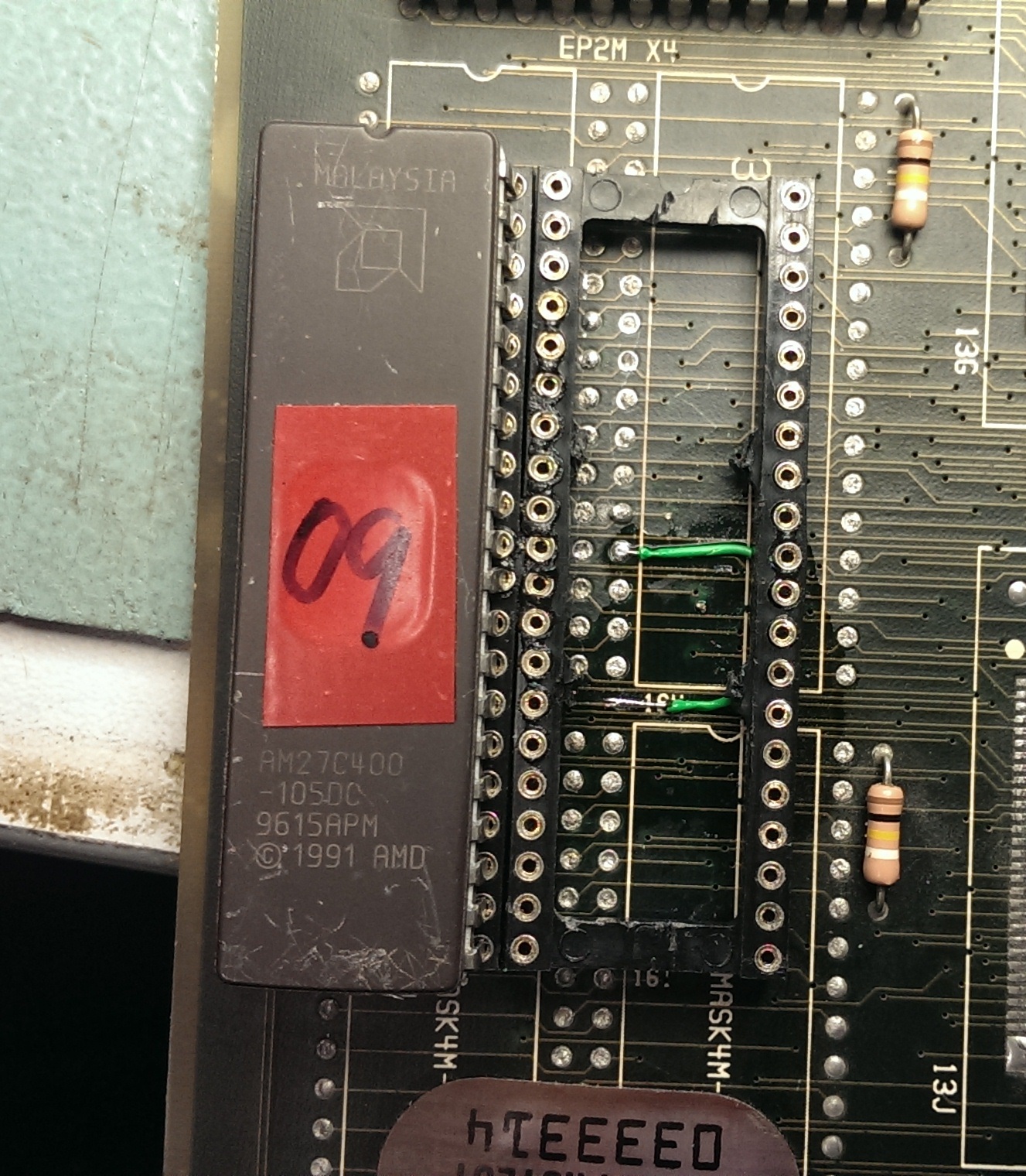
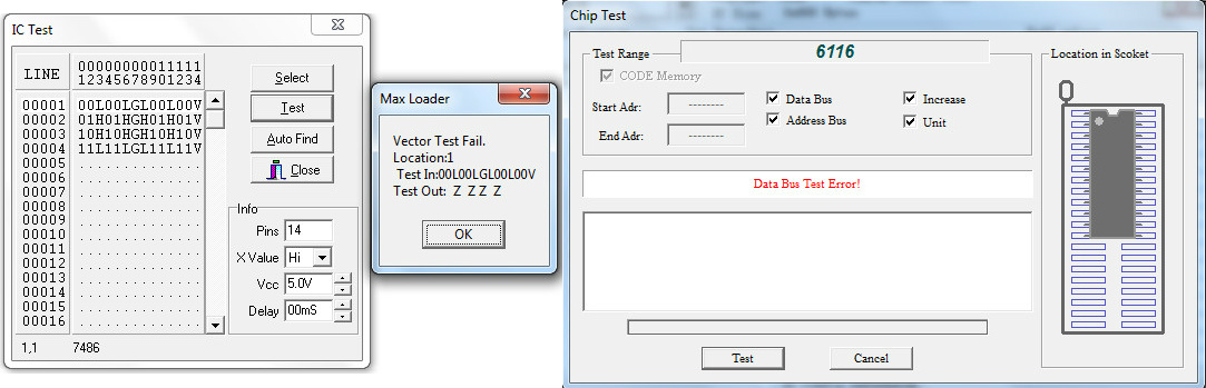
The 74LS86 @IC72 had stuck outputs and these are tied to some ADDRESS lines of a TMM2018 SRAM which had some silent DATA lines, too.So I prontly desoldered them and they failed once tested out-of-circuit:
I thought my job was done but I was wrong since this improved the sprites but not fully restored as they still missed some lines symptom of missing DATA:
![]()
So I kept to check the OBJECT circuitry until I come across the TMM2018 SRAM @IC20 which had four silent DATA lines (PIN14-PIN17).I piggybacked it and magically all sprites were restored:
![]()
PCB 100% fixed and another one preserved!
Just a note for future reference : there are five TMM2018 (6116 equivalent) sprites RAMs and they are @IC73, @IC81, @IC84, @IC120 and @IC7 on VIDEO board.