Atari Asteroids Deluxe repair log

 PCB Repair Logs  Comments Off on Atari Asteroids Deluxe repair log
Feb 202016
 

Sometimes lightning does strike twice.

I was recently sent an Asteroids Deluxe PCB which was exhibiting corrupted vectors.

When I got the PCB, I put it on my test rig and was presented with the following in TEST mode;

IMG_20160215_160220667

GAME mode;

IMG_20160215_160158687

The symptoms were pretty much identical to the last Asteroids repair log I posted.  Note however this is an Asteroids Deluxe, however it is pretty much identical hardware to Asteroids except that Asteroids Deluxe has a pure digital sound circuit via a Pokey chip (Asteroids is analogue and no Pokey).

I immediately probed the 74LS42 decoder at E6, which had two outputs stuck HI.

IMG_20160215_160124793

So I desoldered it;

IMG_20160215_161027015

Tested it in my IC tester;

IMG_20160215_181037047

Socketed and replaced it with a fresh decoder;

IMG_20160215_161344449

Fire her up again;

IMG_20160215_160348150

Now working, except that the PCB would sometimes crash or refuse to boot.  I was able to determine that three of the six ROM sockets were worn.  So I replaced all of them for reliability;

IMG_20160215_162641553

IMG_20160215_165025775

IMG_20160215_162807350

Now working 100%.

Poker Ladies repair log #1

 PCB Repair Logs  Comments Off on Poker Ladies repair log #1
Feb 202016
 

I recently received some faulty Capcom pre-CPS PCBs.As most of you know, these board are well known to commit suicide.As you can read from the Dead Battey Society site, “the way suicide work is that the batteries on board supply power to a bit of RAM that holds a decryption table. This table is the key to decrypting the encrypted program stored in the board’s ROMs. When the battery dies, this table goes away and the program code can no longer be decrypted. The CPU no longer has valid code to execute. The board stops working”.

In particular Capcom pre-CPS boards all use a single 3.6V battery and a custom Z80 marked “Kabuki”.The Kabuki has the RAM with the decryption table built right into it.

My Poker Ladies PCB committed suicided and all I got was a static blue screen:

Poker_Ladies_suicided

After reviving it with the use of patched ROMs available from the Dead Battery Society site and doing some modification on PCB (thanks to Corrado for providing me info), the board successfully booted but showed sprites issue:

sprites_issues

EPROMs containing this part of graphics were reafd fine so my first suspicions were on the custom sprites generator marked “86S105” (84 pin PLCC package) which addresses the devices :

86S105_sprite_generator

I played the card of its replacement taking a spare from a shorted Block Block PCB:

86S105_removed

and I won since sprites were fully restored:

sprites_restored

 Posted by at 9:38 pm

Bubble Bobble (bootleg) repair log

 PCB Repair Logs  Comments Off on Bubble Bobble (bootleg) repair log
Feb 202016
 

I never had a Bubble Bobble PCB in my collection so recently I bought this bootleg board (original one is too expensive for my taste) called Super Bobble Bobble :

Bubble_Bobble_bootleg

When I powered it up, at first glance it seemed to play fine except for the lack of sound which I promptly fixed reseating and cleaning the sound CPU ROM.But playing some games I noticed that screen was yellowish :

color_issue

Shorting some data/address lines of various RAM I could identify the ones related to palette circuitry, two TMM2015 (6116 compatible)

palette_RAMsha

Probing the lower one with a logic analyzer revealed that some address lines were stuck low:

TMM2015_DATA_bus

This lead me to remove and testing the chip out of circuit where it failed:

TMM2015_palette_failed

TMM2015_recplacing

With a good RAM chip correct colors were restored:

correct_colors

End of job.

 Posted by at 4:51 pm
Feb 162016
 

Got the second board fixed up today.
This one had a lot more wrong with it and all caused by a previous repair attempt.
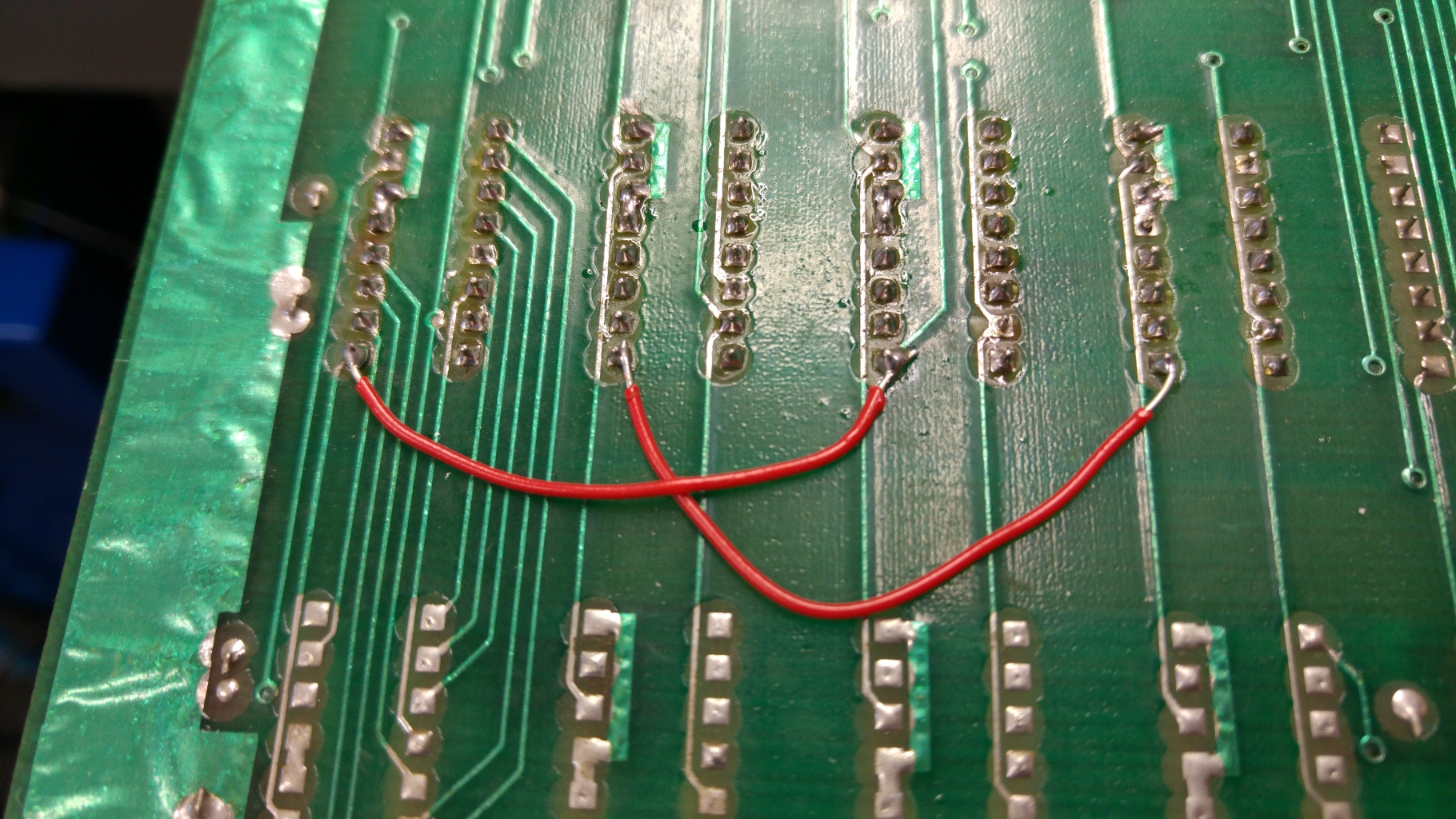
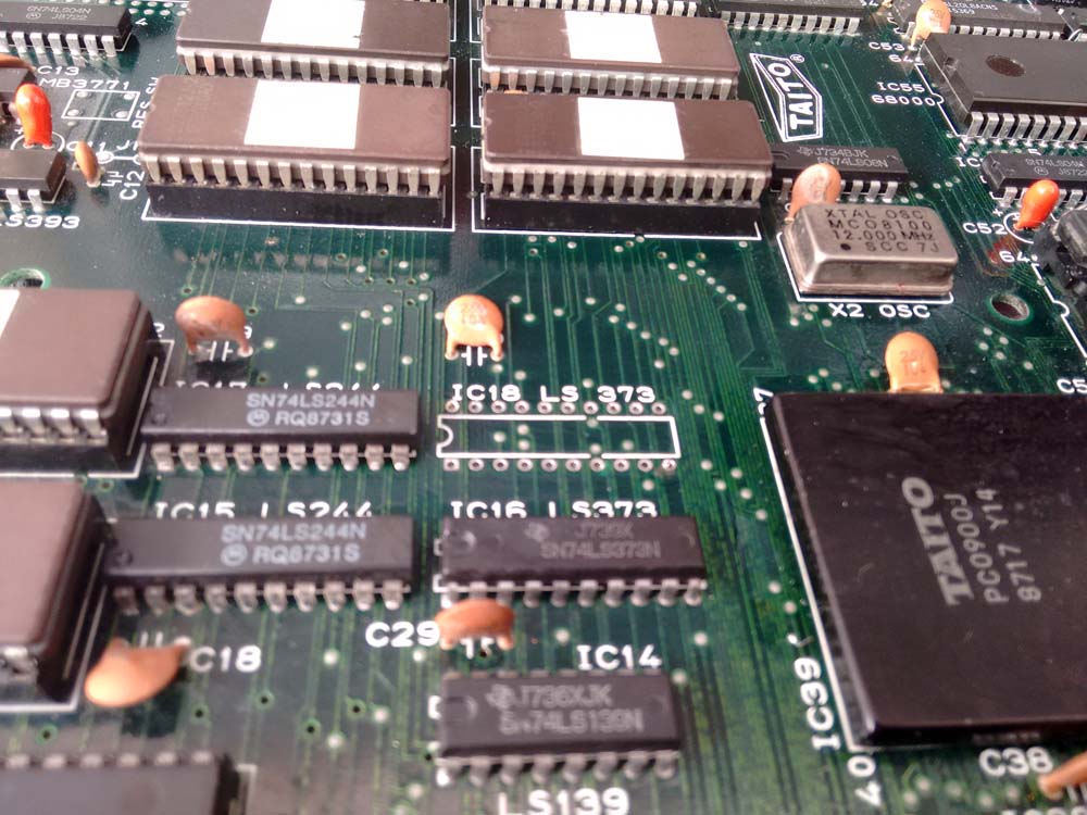
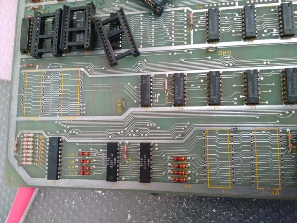
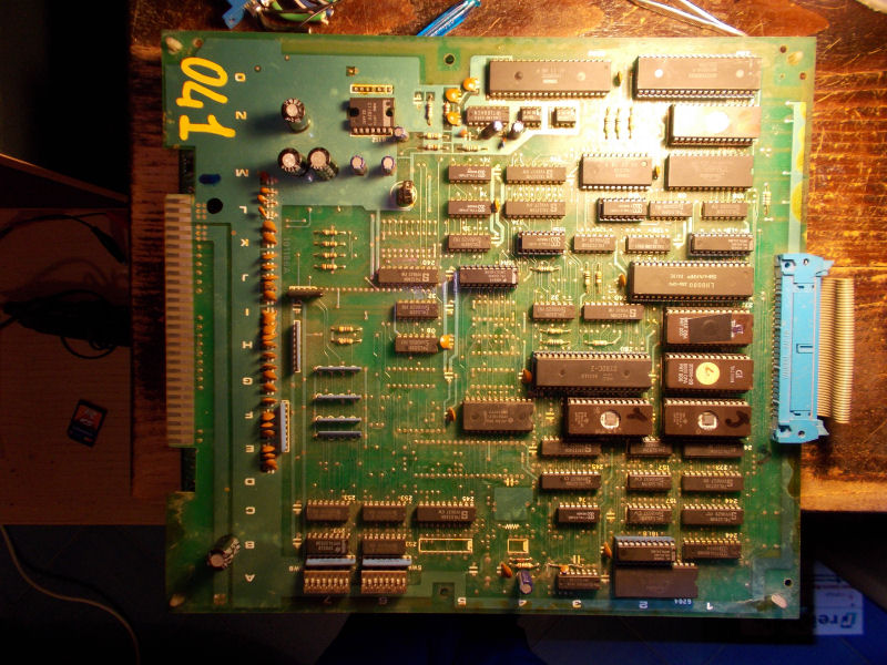
Visual inspection immediately revealed this.
20160207_133009

I confirmed these wires were going where they should be and neatened them up a bit.

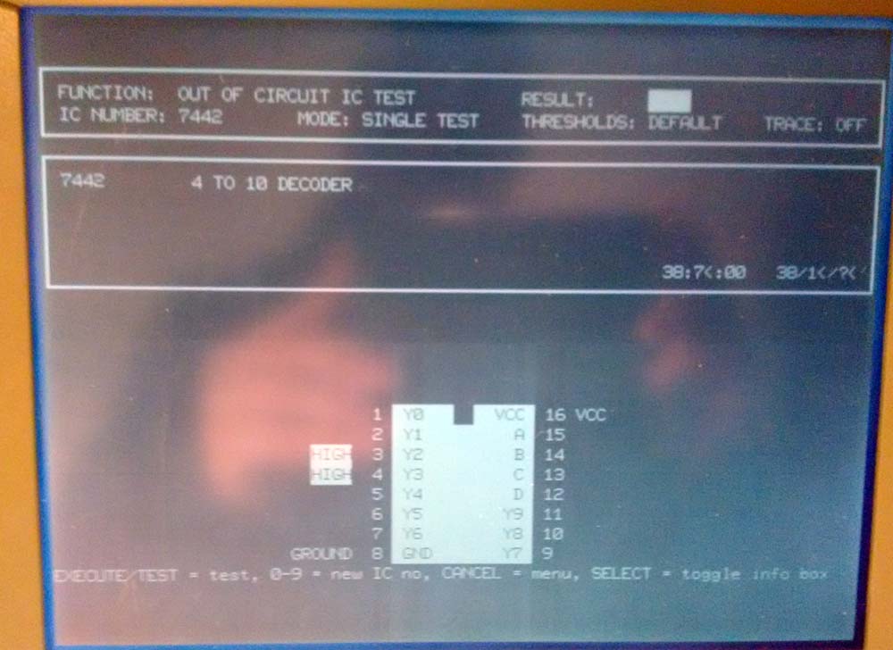
As with the first board all I got was a blank screen with the board not playing blind. At this point I had my smaller custom replacements verified so could do away with stacking the TTL riser and could just plug the Fluke straight in.
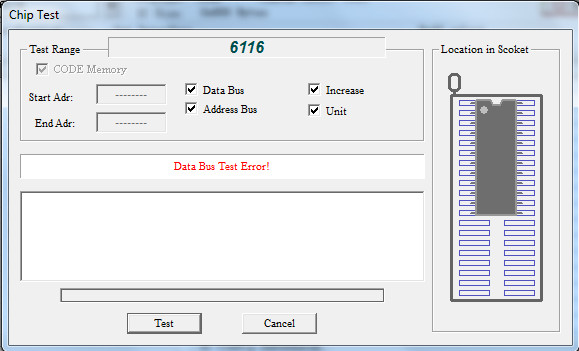
ROM checks were all good but the RAM checks failed straight away.

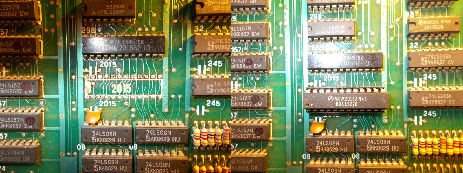
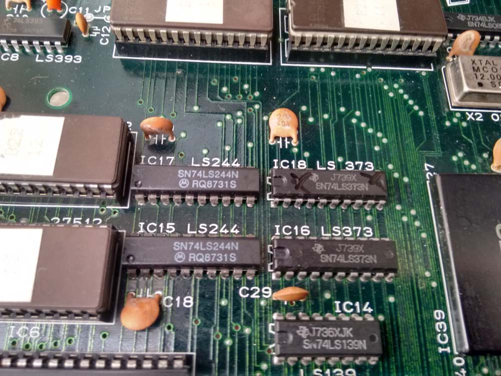
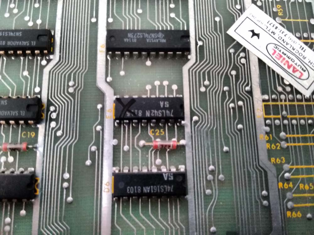
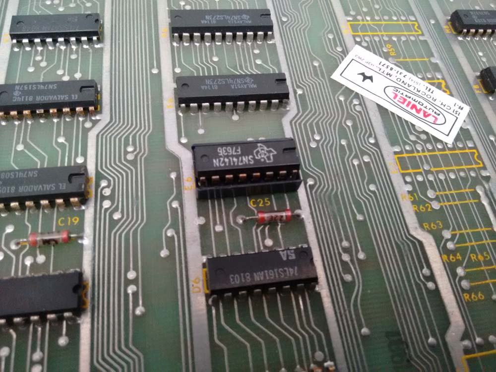
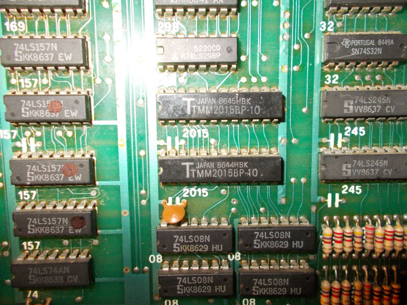
With the previous repair still fresh in my mind I knew where to look. the 74LS245 at 4H. This had a turned pin socket fitted and a 74HC245 chip inserted. The HC variation means its CMOS logic levels and typically aren’t an ideal replacement for LS parts. If you are going to swap them out you can use the HCT variety which are TTL compatible.
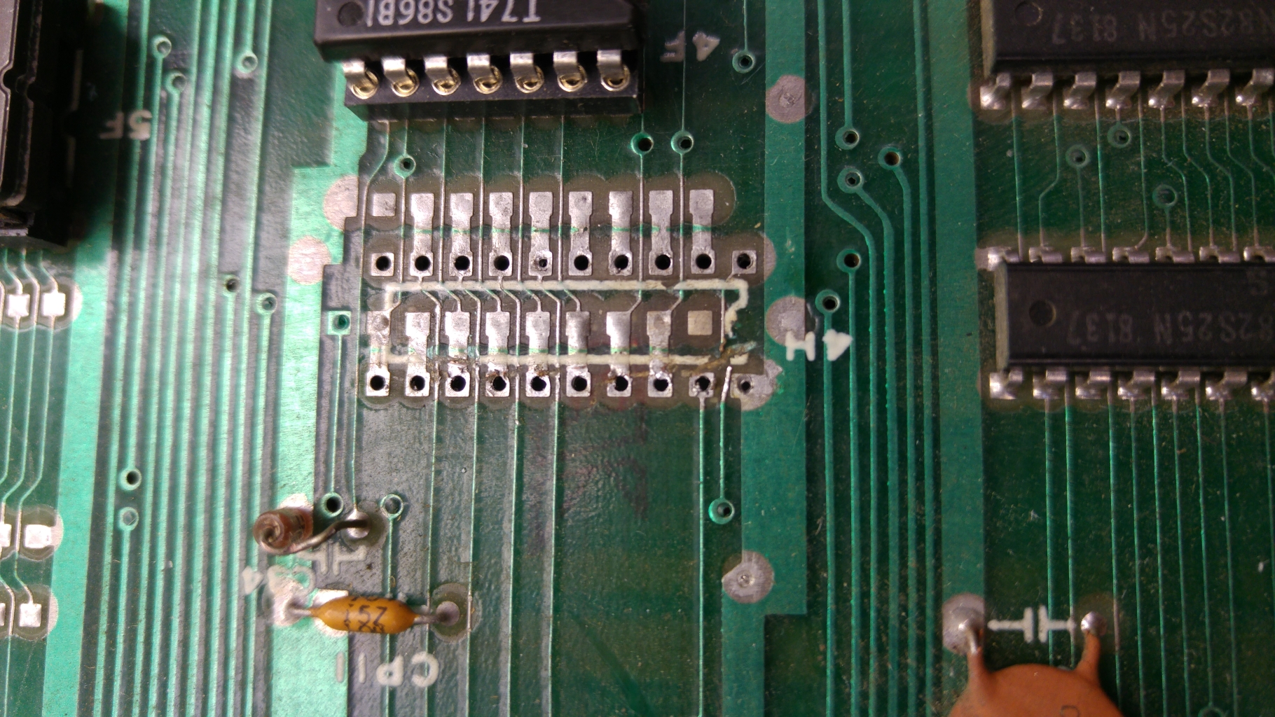
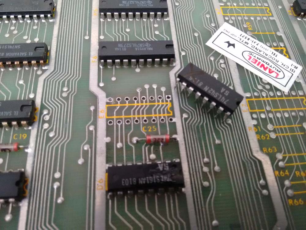
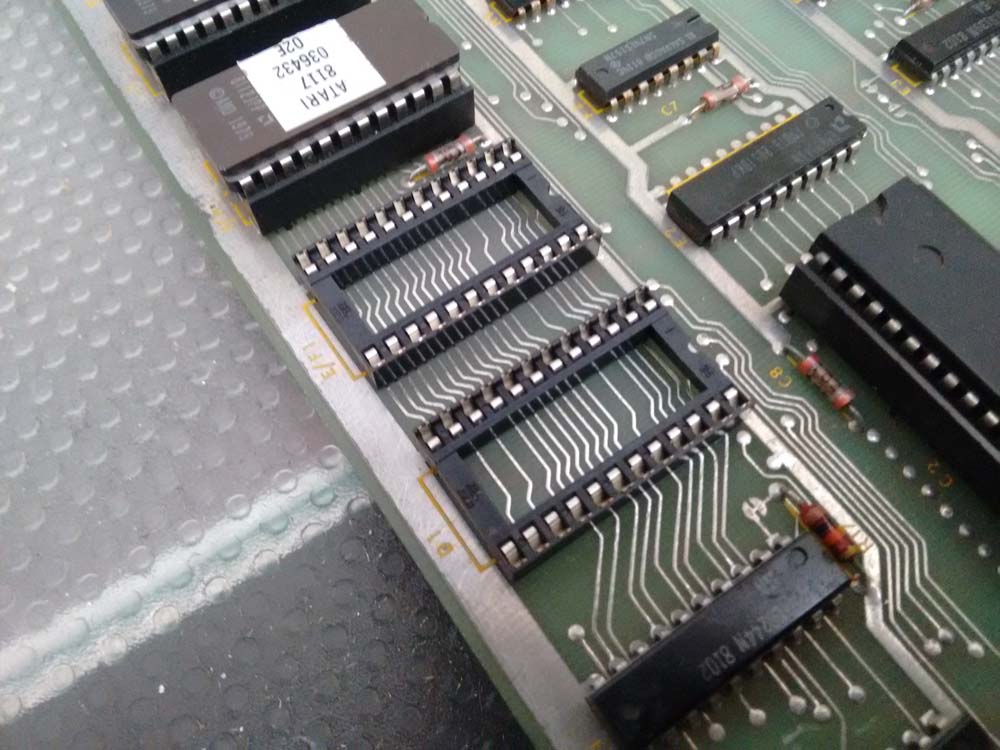
I replace this chip with a 74LS245 but it did not fix my issue. Checking the outputs of the 245 to the RAM led me to suspect a poor desoldering job of the previous chip as several pins weren’t connected to the RAM. I desoldered the socket and found this mess.
20160207_133720

You can clearly see a the traces that have been ripped through. I patched these, fitted a new socket and continued my checks.
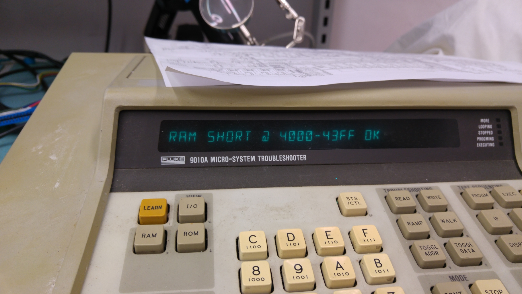
The Fluke now reported this.
20160215_203212

Knowing the chip was good and the connections to the RAM were good I focused my attention on the CPU side of this chip.
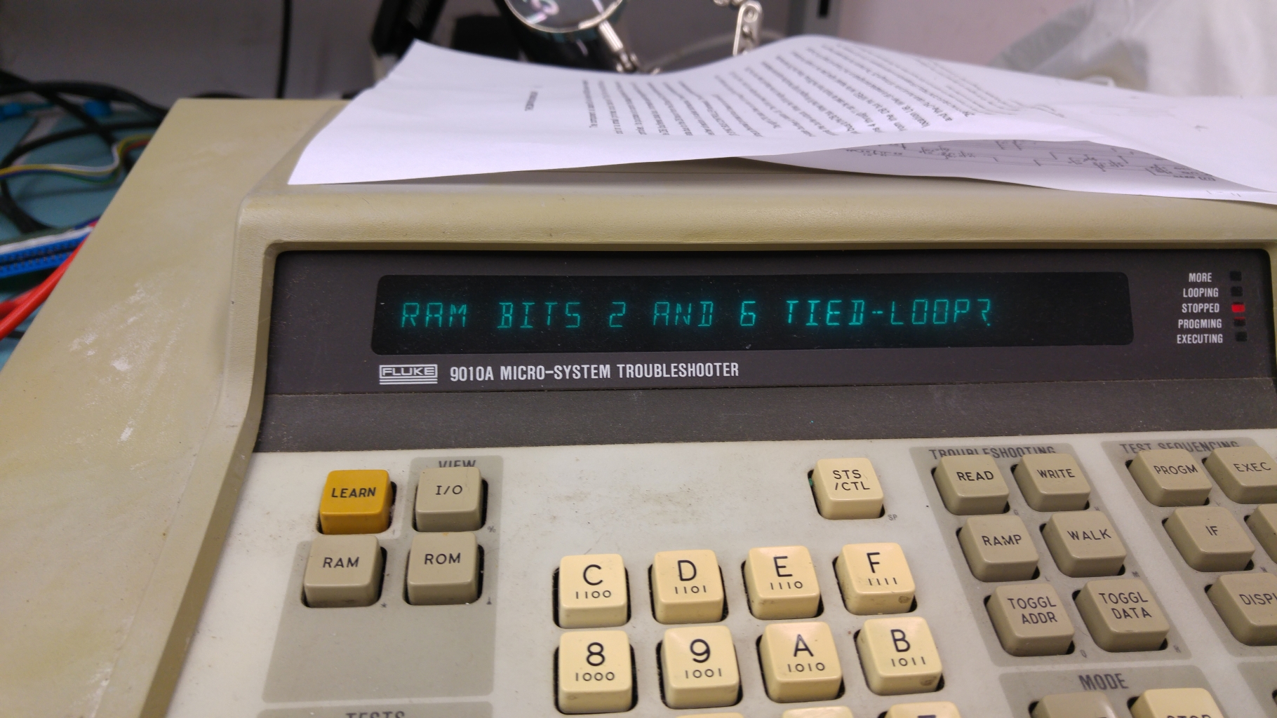
I knew my custom chips were good and I could correctly read the ROM’s so new the CPU socket was good. This didn’t leave me with many places left to look. I could almost certainly rule out some places as data bits 2 and 6 were across two different chips and the chances of both of the chips shorting together was a bit low. This left me with an 74LS273 at 4D and also to the dreaded crusty flux issue. Cleaning the flux cleared my short.
20160215_205328

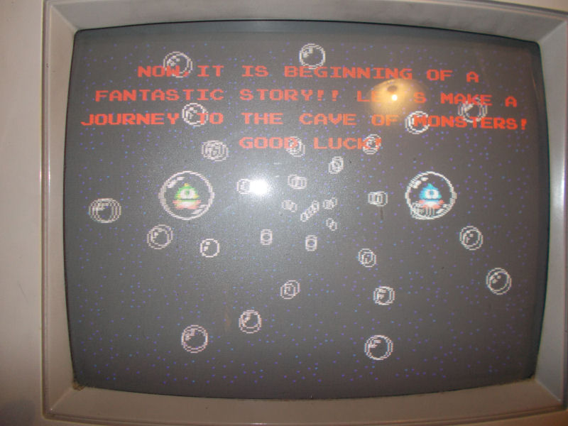
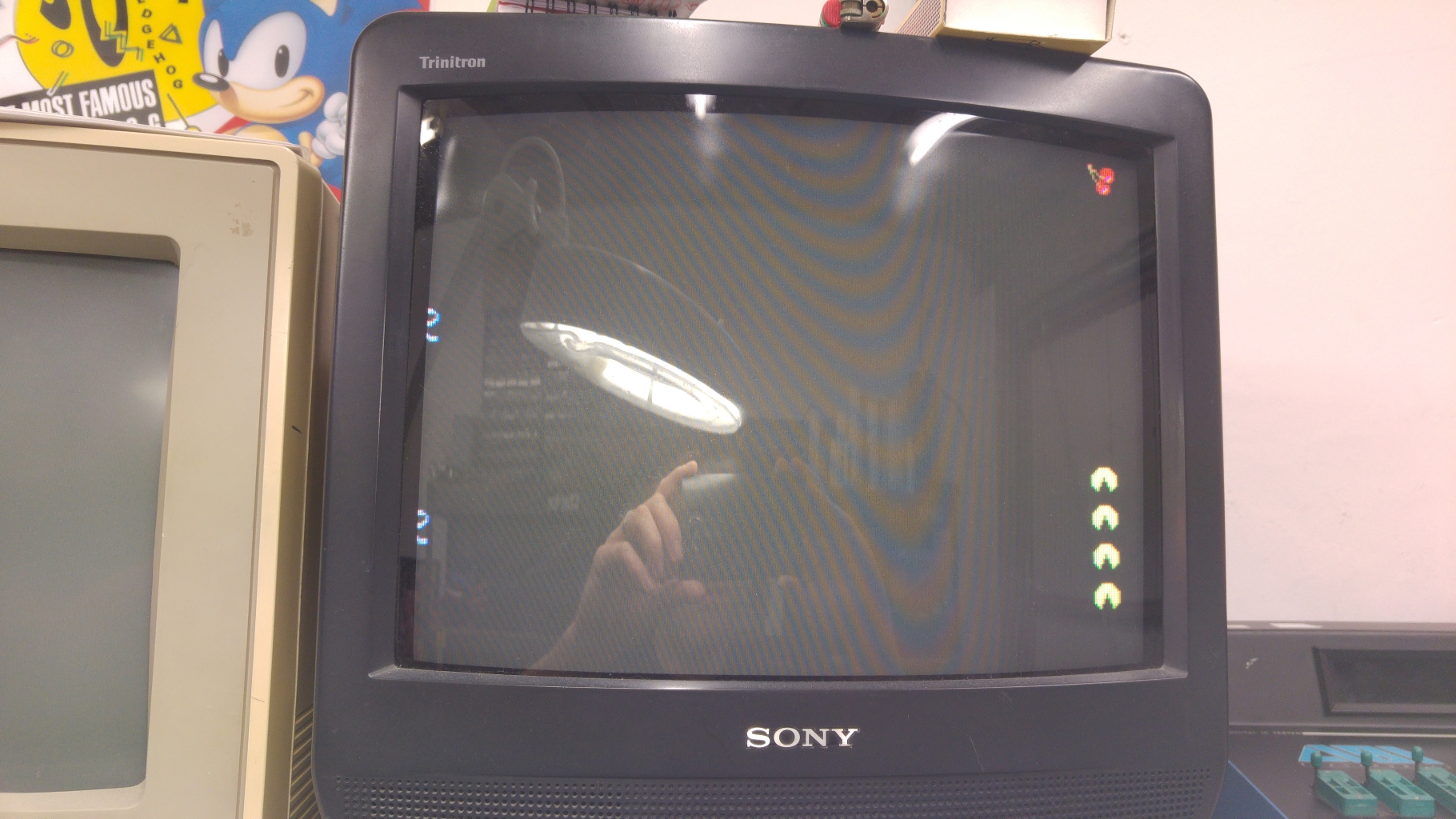
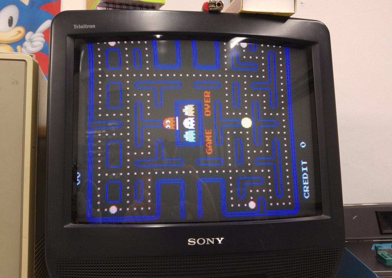
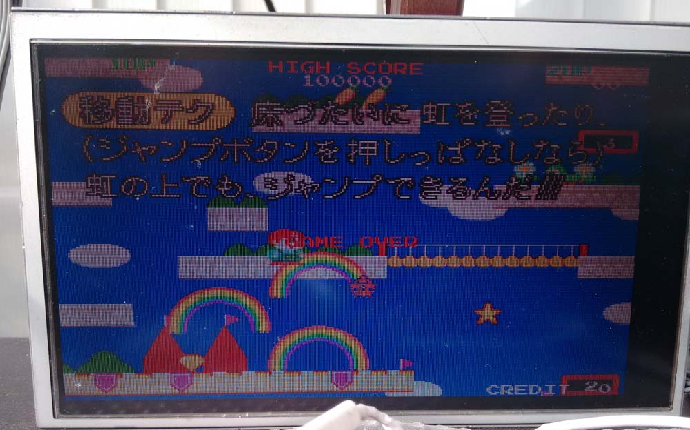
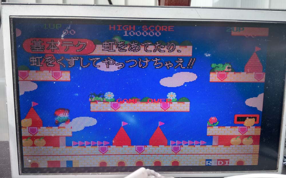
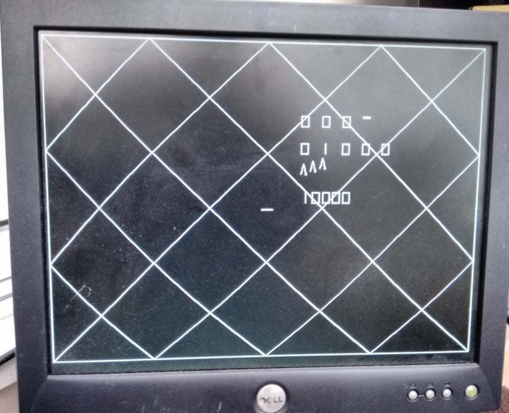
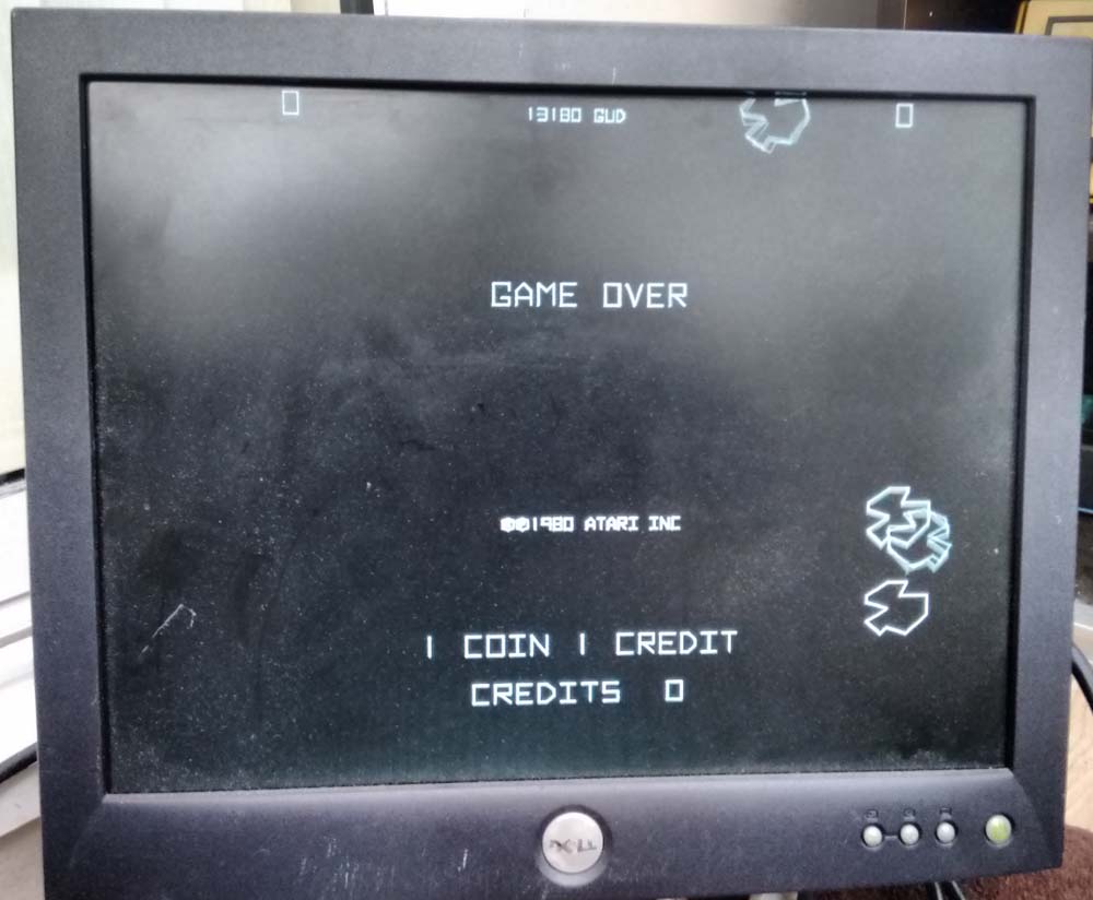
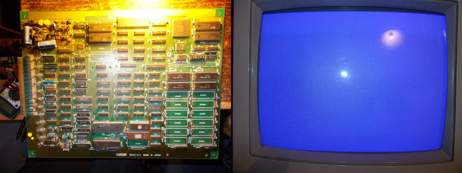
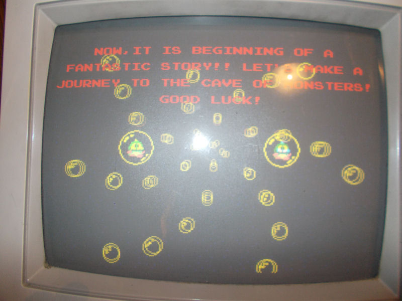
Now the game would boot but I get this
20160215_205526
Only the score and credits were showing. If I started a game the lives were also showing at the bottom.

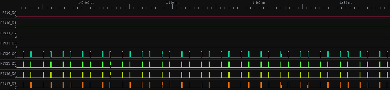
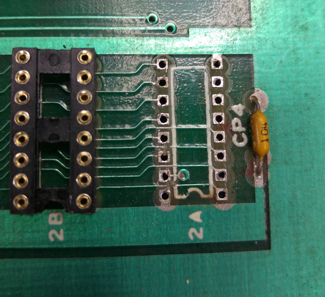
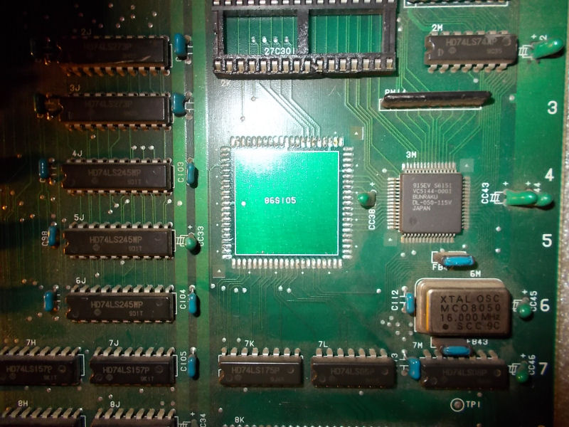
My attention immediately went to the 4 x 1bit RAM chips at 2A-2D and found there wasn’t a great deal of activity and some missing signals.
My heart sank right away as I could see turned pin sockets had also been fitted for all of these which most likely meant the same person had replaced them.
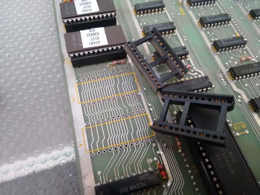
Sure enough there were several traces cut. I did remove one of the sockets just to see what I was up against.
20160216_193306
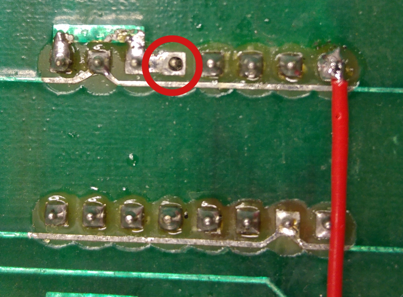
Some severed traces here and doing a continuity test revealed more and more. I also found one pin not soldered.
20160216_194329

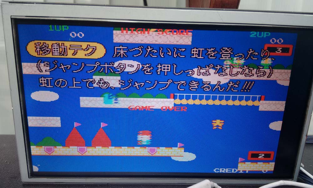
A bit of time later after patching and verifying my work I fired it up and was all ready to feel pleased with myself on a job well done but the same fault was still present.
Confident the fault was still in the area I was already working I set back to work checking continuity and found the ‘Data In’ pin (pin 15) of a RAM at 2A was shorted to pin 1 of the RAM at 2B. Looking back at the picture I had taken I noticed a bit of stray solder bridging the trace that ran adjacent to pin 15 that I had missed earlier. I managed to remove it with a pin and a bit of patience.
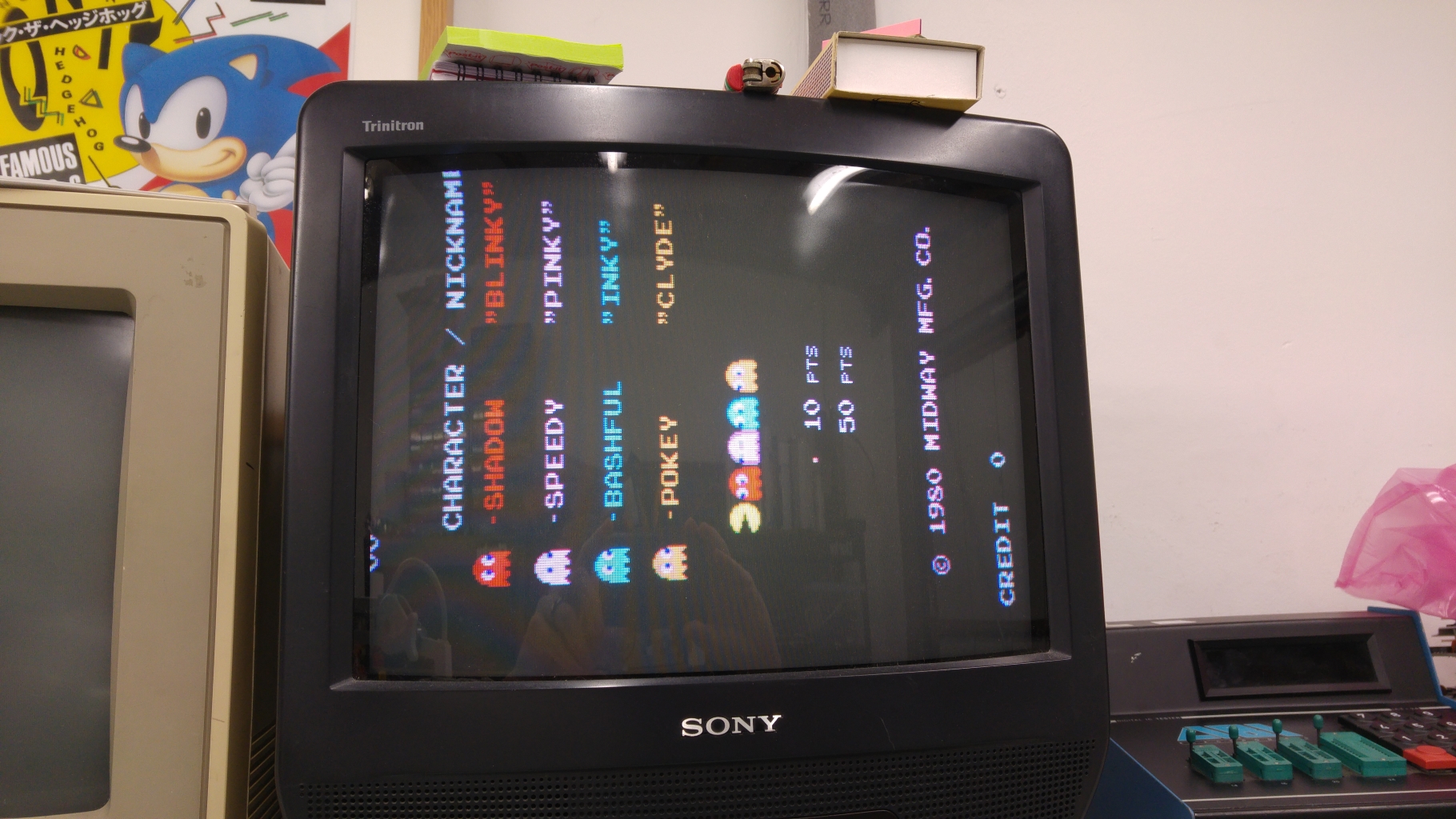
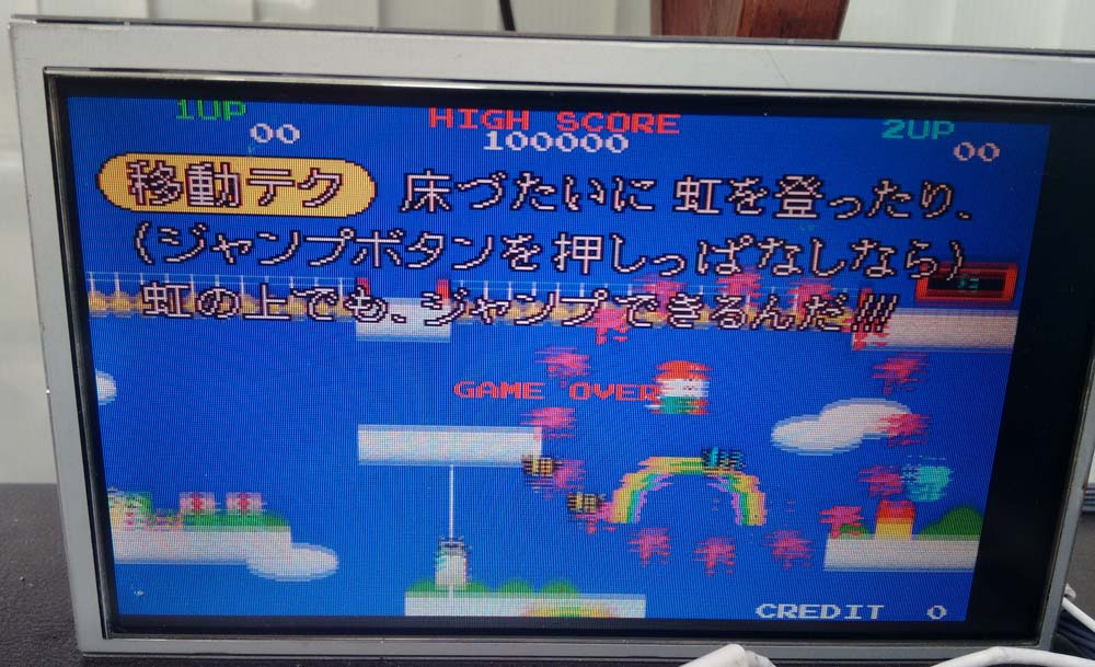
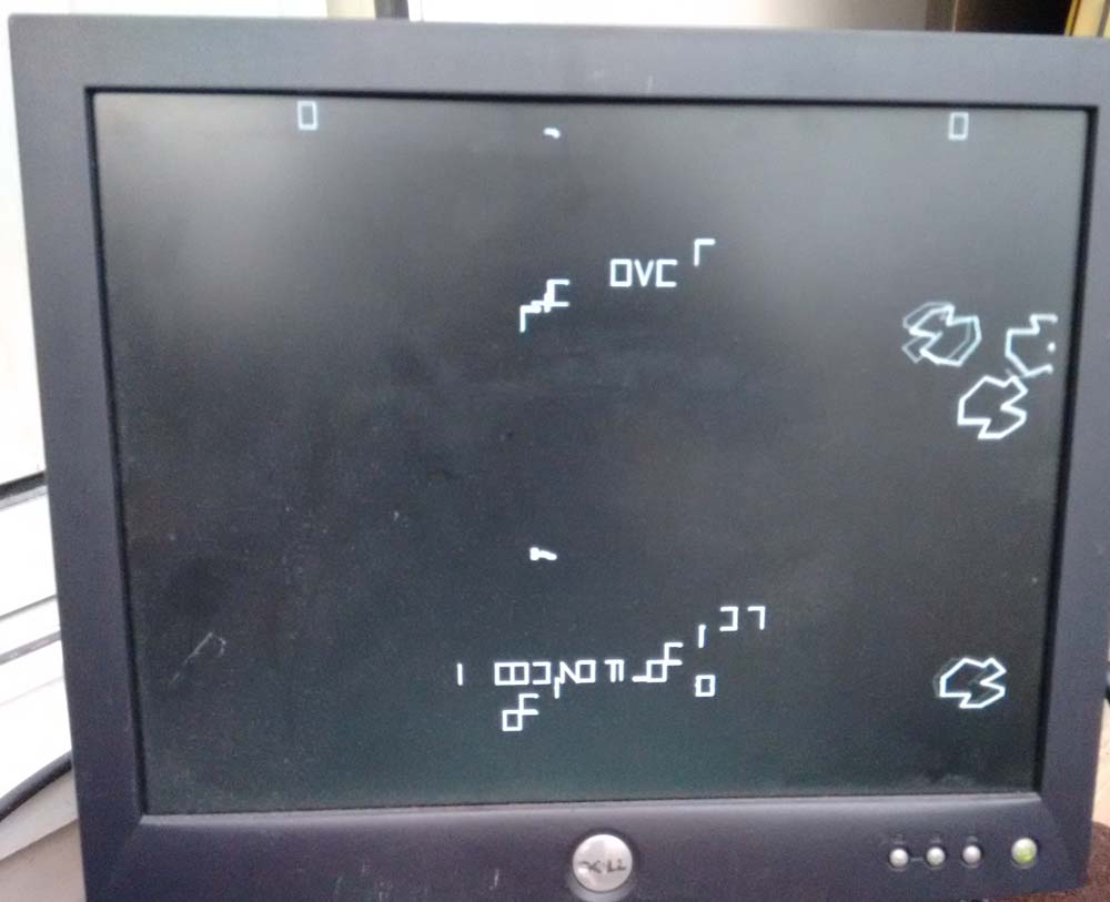
After that the board fired right up and plays fine.
20160216_201142

20160216_201150

 Posted by at 9:21 pm

Pac-Man repair log #2

 PCB Repair Logs, Repair Logs  Comments Off on Pac-Man repair log #2
Feb 142016
 

I recently asked on UKVAC if anyone had a Pac-Man PCB I could borrow in order to test the recreations of the two custom chips I made for the CPLD replacement device.
JonHughes replied and a few days later I had not one but two PCB’s to play around with.
One was pretty much stripped of parts but the other was complete and even had the TTL versions of the two customs.
I already have a JAMMA adapter for this that I made for my first Pac-Man repair so I was all ready to go.
Visual inspection revealed nothing to be concerned about so I went ahead and fired the game up.
I got nothing. The game was absolutely dead. I checked for activity on the CPU address and data bus but they were static.
Checking the clock pin also showed up no activity. Probing around the clock section suggested that the crystal had died so I went ahead and replaced it but this didn’t help.
There was a small build up of old flux around capacitor C4 so I went ahead and cleaned this up. The clock signal came back!

So now I had this my clock back and activity on the address and data bus lines but I still had a blank screen and it wasn’t making any noise. I also confirmed the board was not watchdogging.
Since the Z80 CPU is already socketed I decided to use the Fluke 9010 to check the ROMs/RAMs. Here is where a little problem came as the TTL custom replacement covers over the Z80 so I fitted a few header to the pins to raise it up enough to fit the Fluke pod.
20160206_195844
With the Fluke connected I quickly verified the ROM’s and RAM’s were fine. It also verified that the connections between these chips and the Z80 were good.

Next step was to work backwards from the RGBS pins at the edge connector.
There was obviously no video output.
I found there was no activity coming out of the 74LS157 at 3A but some activity going in and to/from the connecting chips.
pacman_strobe

Checking the strobe pin (pin 15) of this chip I found the signal was stuck HIGH which basically means the chip was disabled.
Checking the 74LS00 at 4C showed I had activity on pin 12 but pin 13 was stuck HIGH. This being the /VBLANK it was clear that this was not correct.

The /VBLANK signal is given out by a 74LS74 chip at 5M.
Checking the signals on this chip I found the clock signal was stuck LOW.
pacman_vblank

This clock signal is 16V signal that is generated by a couple of 74LS161 4 bit binary counters.
pacman_counter

According to my logic probes there was no activity on pins 11 and 12 of the 74LS161 at 2R (the one that generates the 16V and 8V signals) but seeing as though this chip was already in a socket and it tested good in my chip tester I didnt believe what the probe was telling me so I fired up the scope to take a look at those pins.
20160214_165521

This is a good clear example of signal contention. You can see that the signal is trying to rise up but only getting to about half a volt. Knowing that the chip is actually good out of circuit confirms that there is another signal driving it low.
I found that pins 11 and 12 were shorted together.
I couldn’t see anything really wrong physically on the board where these two signals went so once again I opted to clean off the small bit of old flux I could see and once again this fixed my problem.
Although I’ve read about old flux causing issues I’ve never actually seen it myself until now so this has been a lesson learned for me.

Now I got this.
20160214_171848

The game is actually running here but there is garbage on the screen. If I left it running all the sprites came on the screen and were complete.
Before moving on I decided to test out my CPLD implementation of the syncbus controller custom. This gave me the same output so was confident it was OK. Now I though I’d try out the VRAM addresser replacement too and I got this.
20160214_183515
20160214_183521

All fully working with sound too.
The actual cause of the earlier fault was created by me as I had bent 2 pins on the VRAM module during one of the many remove/replace cycles I had done. I since confirmed this works fine too.

That’s this board fully working and the two replacements confirmed working too.

Thanks to JonHughes for providing me with these boards.

 Posted by at 8:36 pm