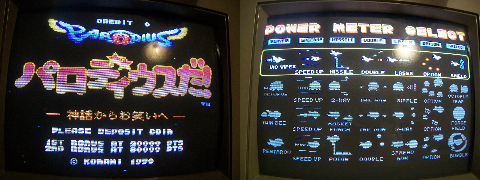
Received this faulty Parodius DA! PCB for a repair:
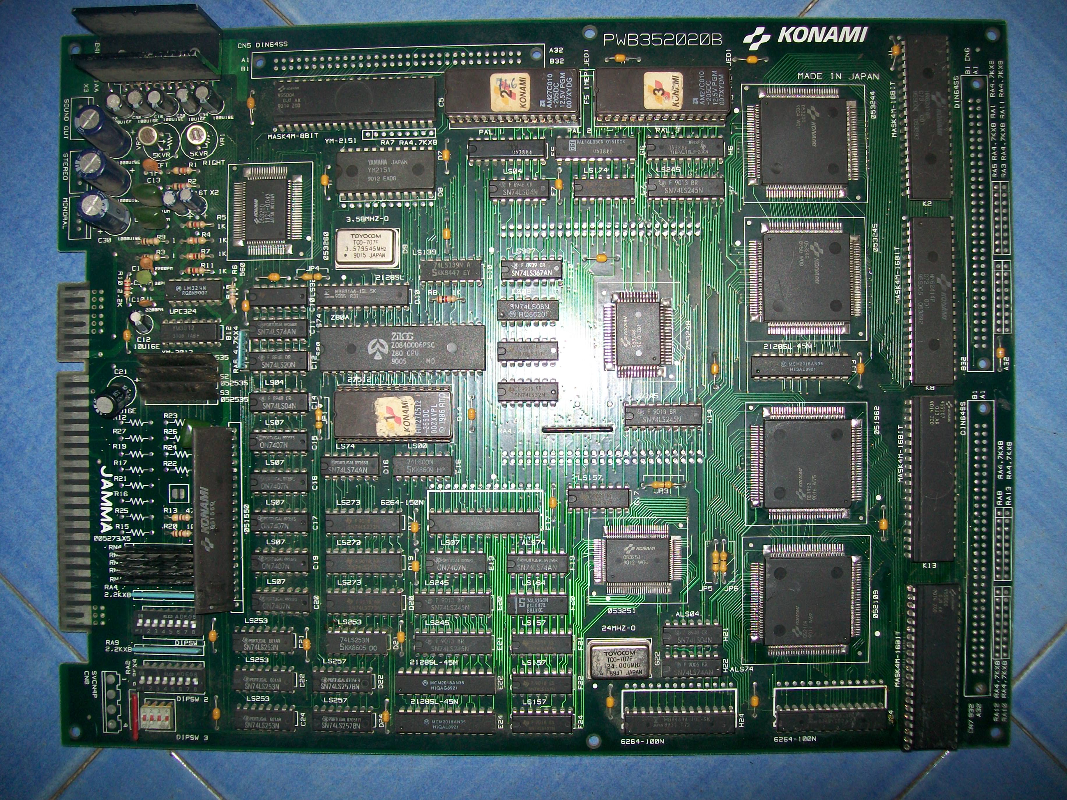
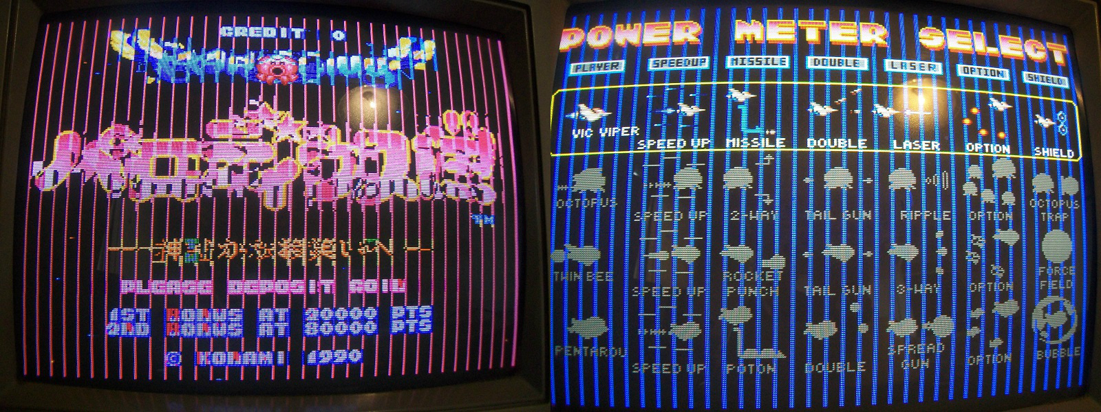
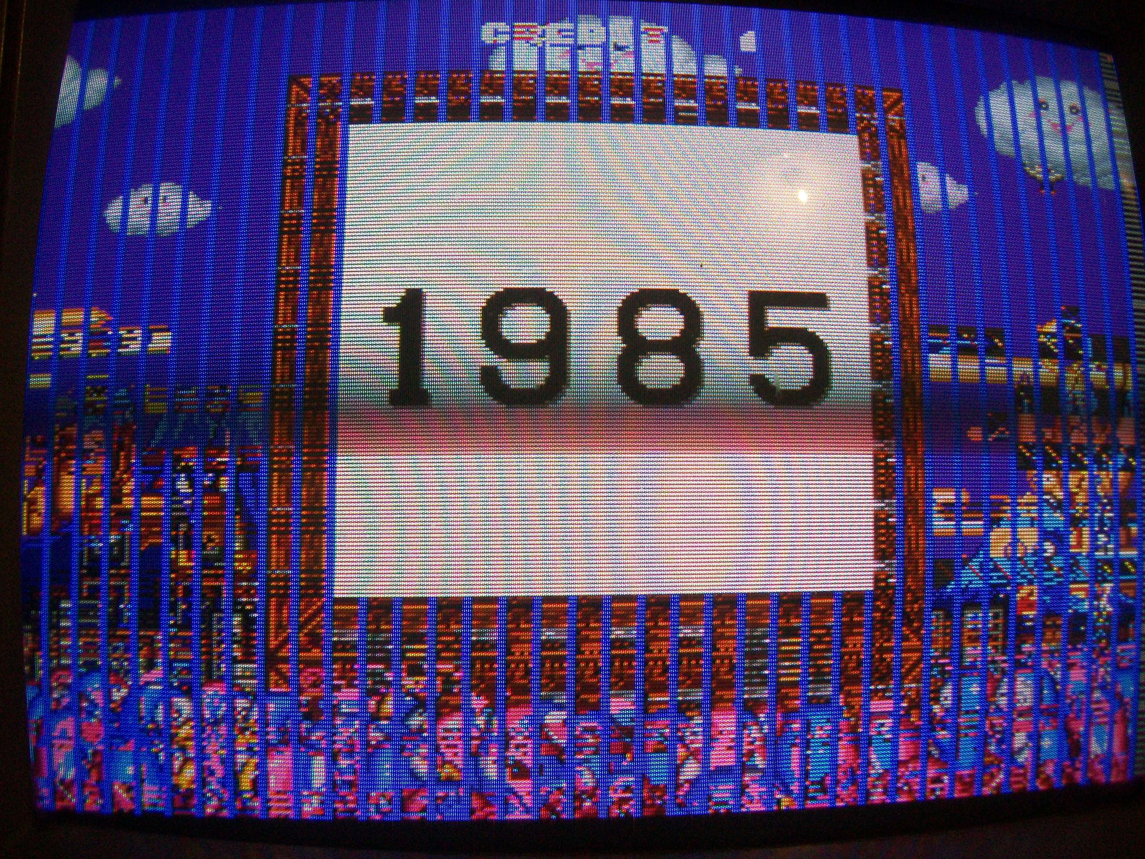
The fault concerned the graphics, there were jailbars all over the screen :
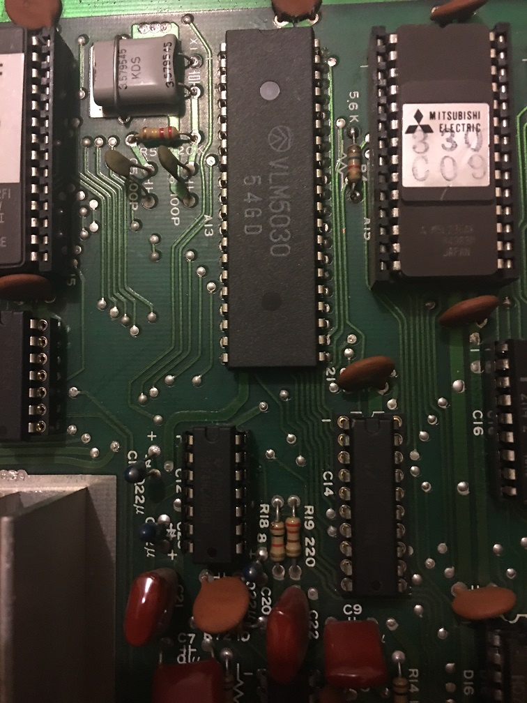
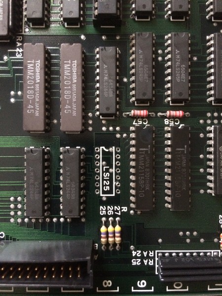
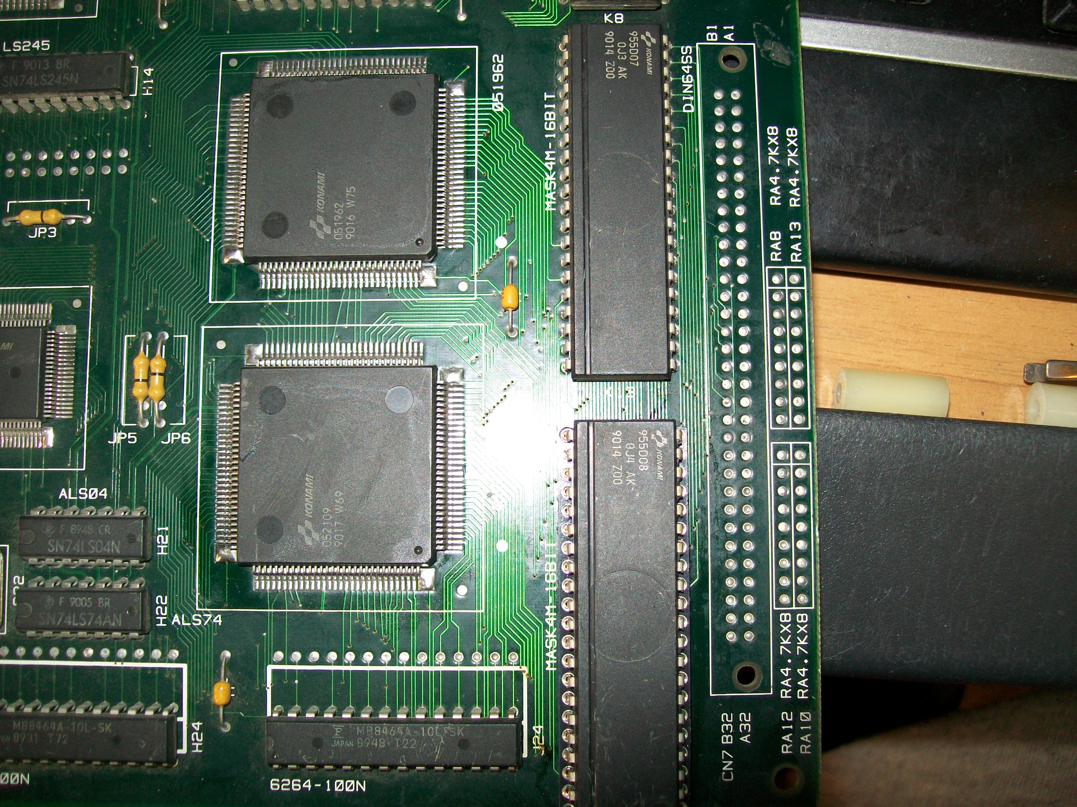
Clearly the tilemap generation circuitry was involved, this is made of two 4Mbit MASK ROMs and two ASICs that work in parallel : the ‘052019’ generates the address lines and the ‘051962’ receives the data from the MASK ROMs and process them :
The MASK ROMs check reported the two devices @K13 and K19 (containin tiles data) as bad:
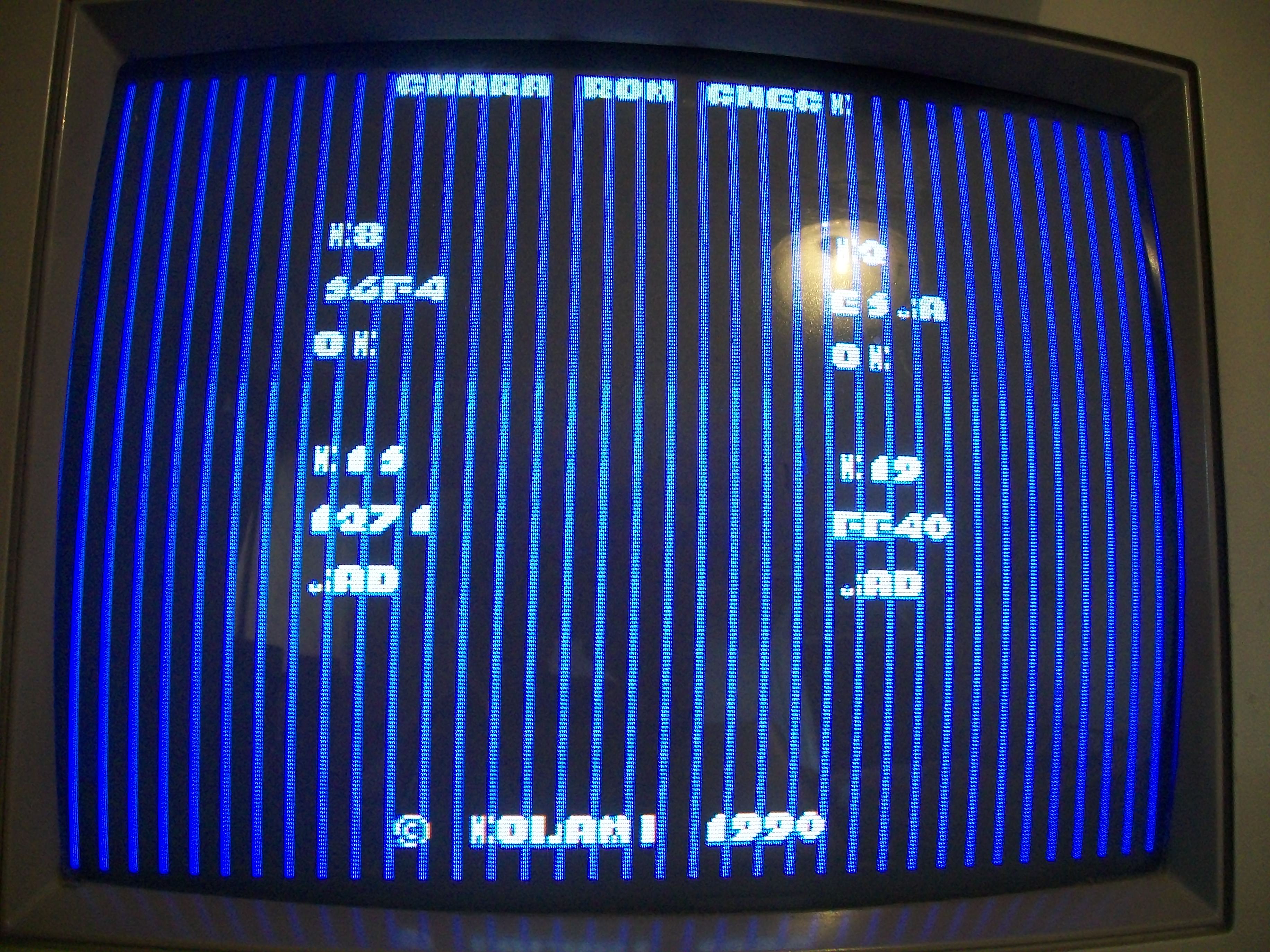
The MASK ROMs @K19 was already removed and socketed.I dumped the device and my programmer warned about a poor contact of pin 13 (data line D0)

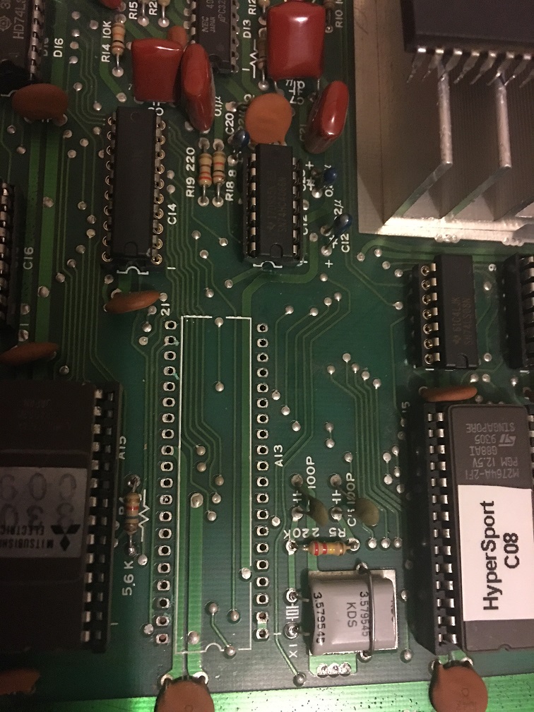
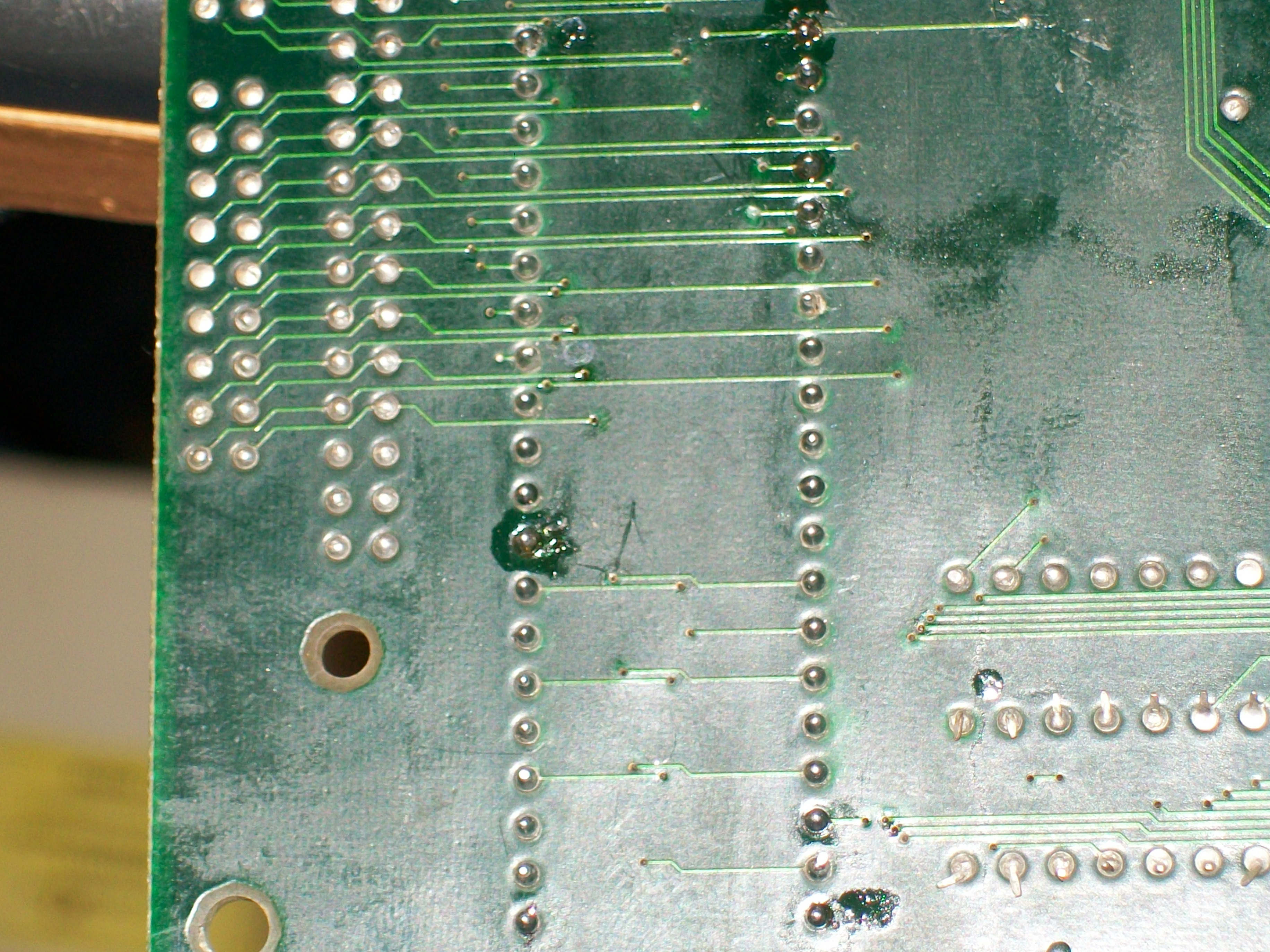
Replacing it with a 27C400 produced very little improvements, the test still reported the two bad MASK ROMs.This meant the main CPU could not reach the two devices (thru the ‘052019’ ASIC) so I went to do a continuity check.All the address lines should be daisy-chained between the two 4Mbit MASK ROM and the ASIC but I found some broken/bad contacts from the one @K19, whoever replaced the device managed to break some connections.Here the solderside overview:
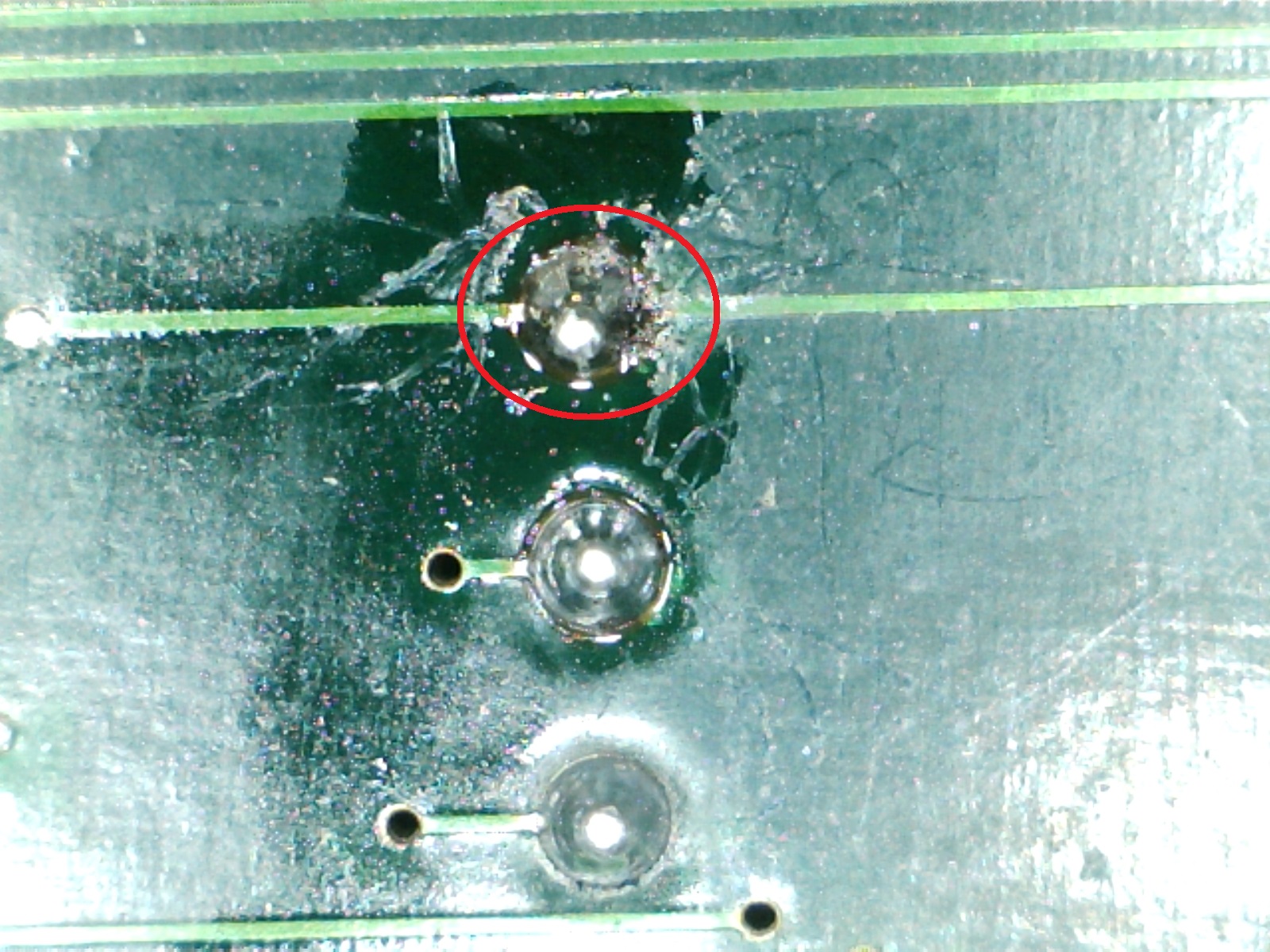
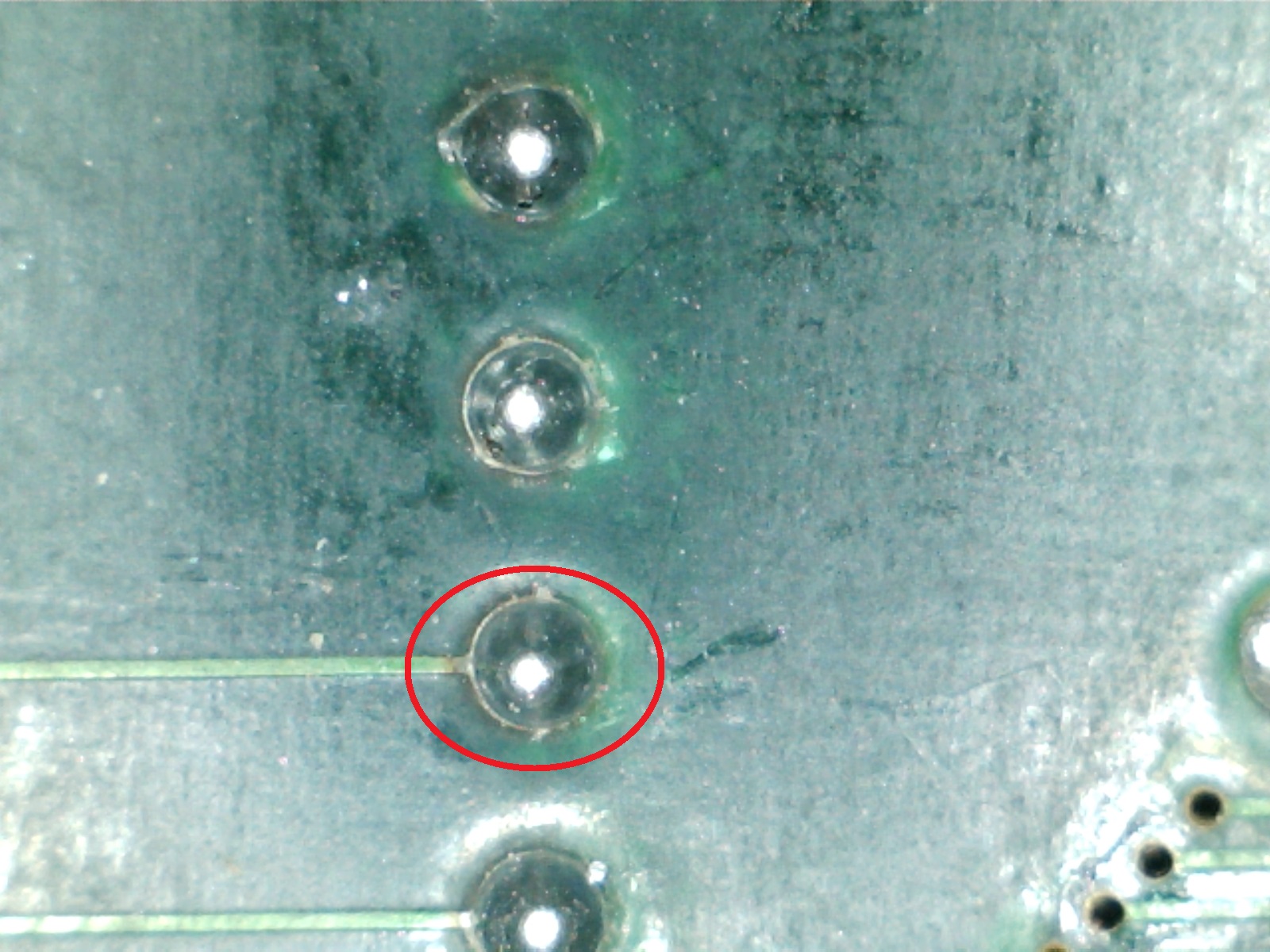
Here are some close-up (taken with a microscope) of the invoved pins (pin 1-5-13)

I restored the connections but still got jailbars:
Chcking the data bus of the tiles MASK ROMs I found a bad via which should have tied pin 29 (data line D19) 0f the device @K19 to the near ‘051962’ ASIC (which processes the tilemap data)
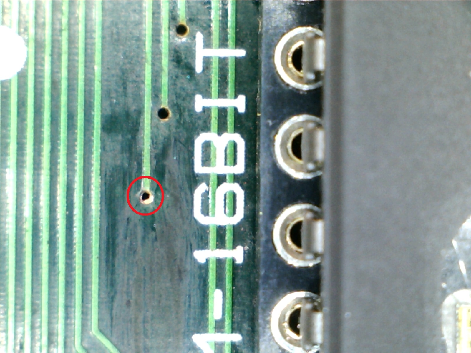
Patching it restored completely the graphics.Job done.