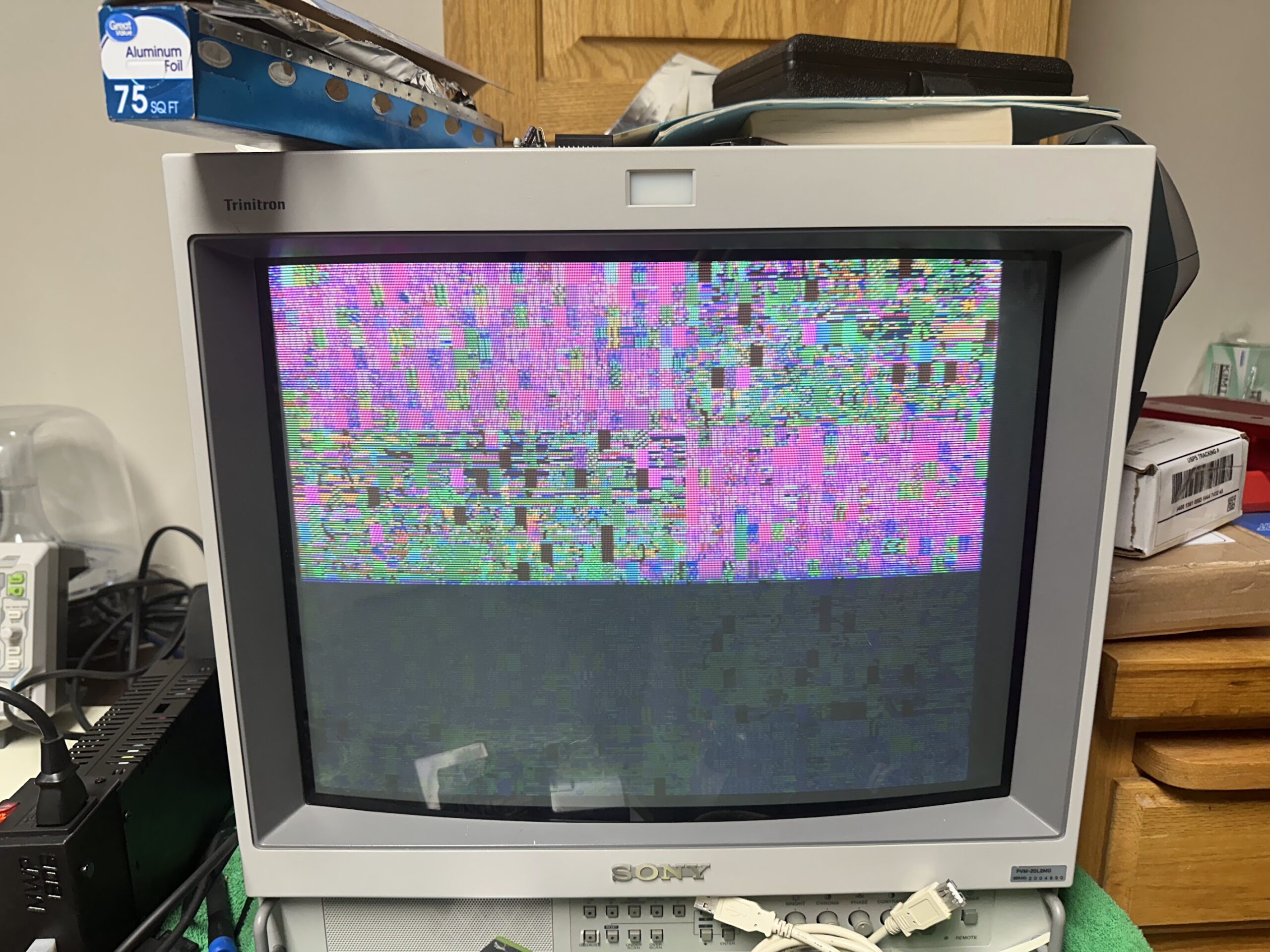
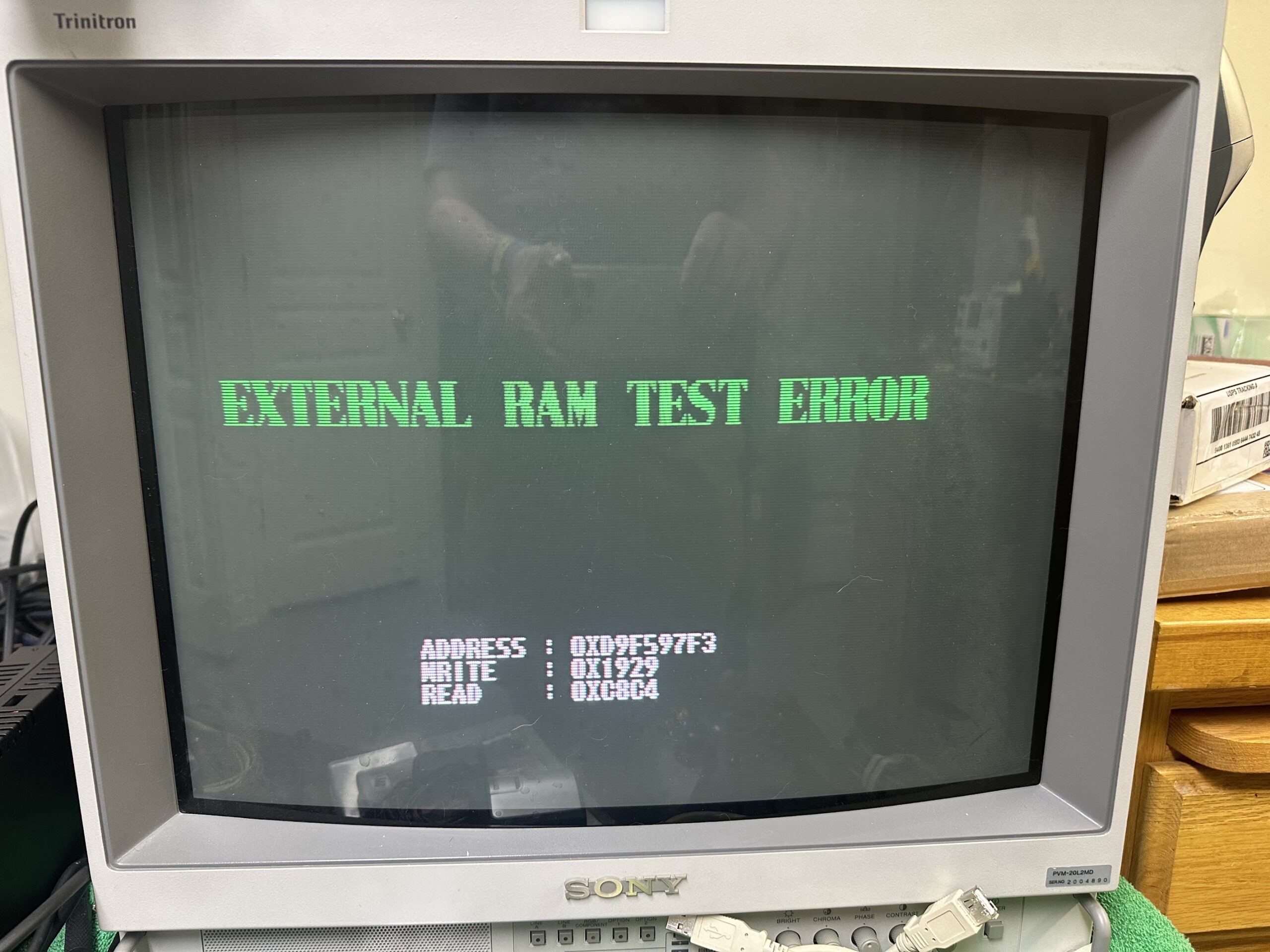
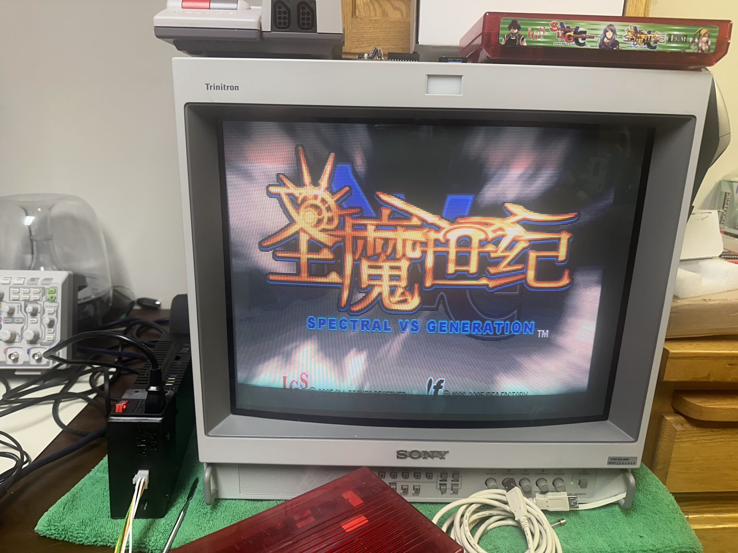
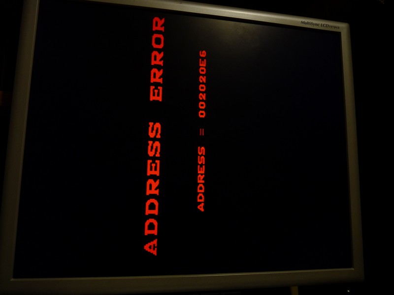
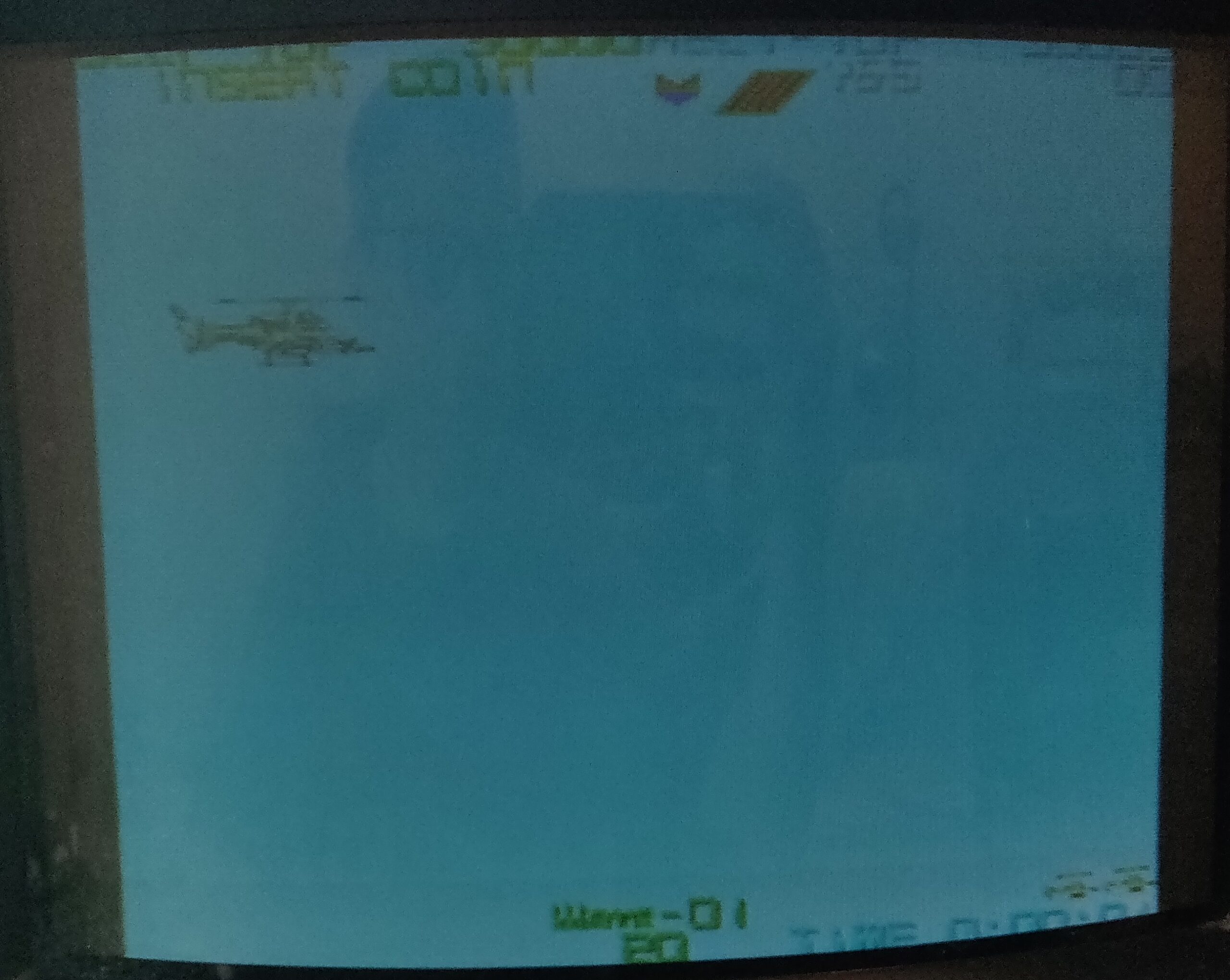
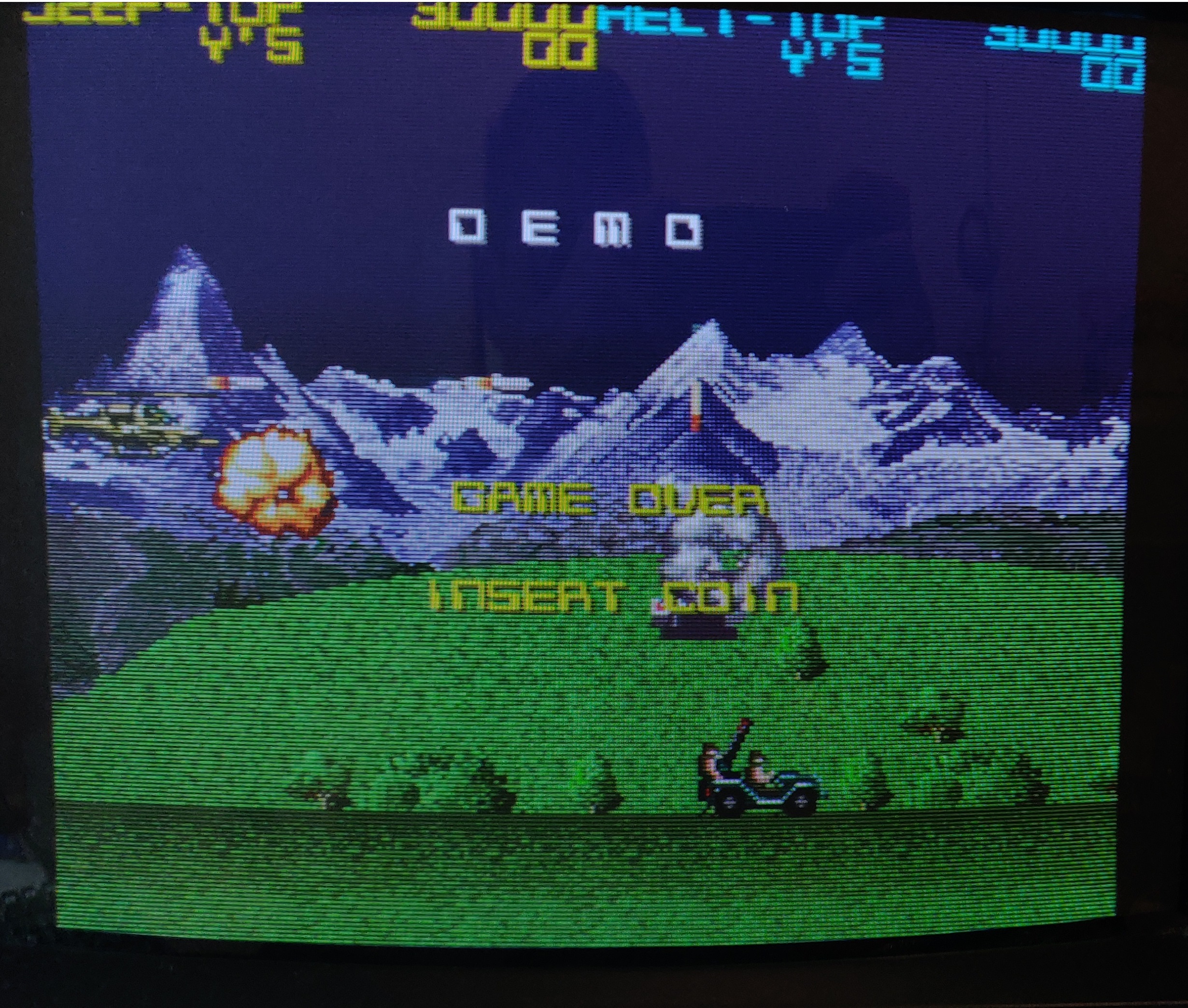
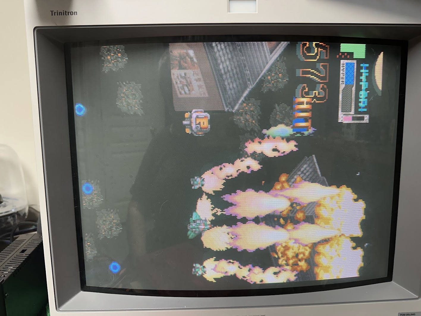
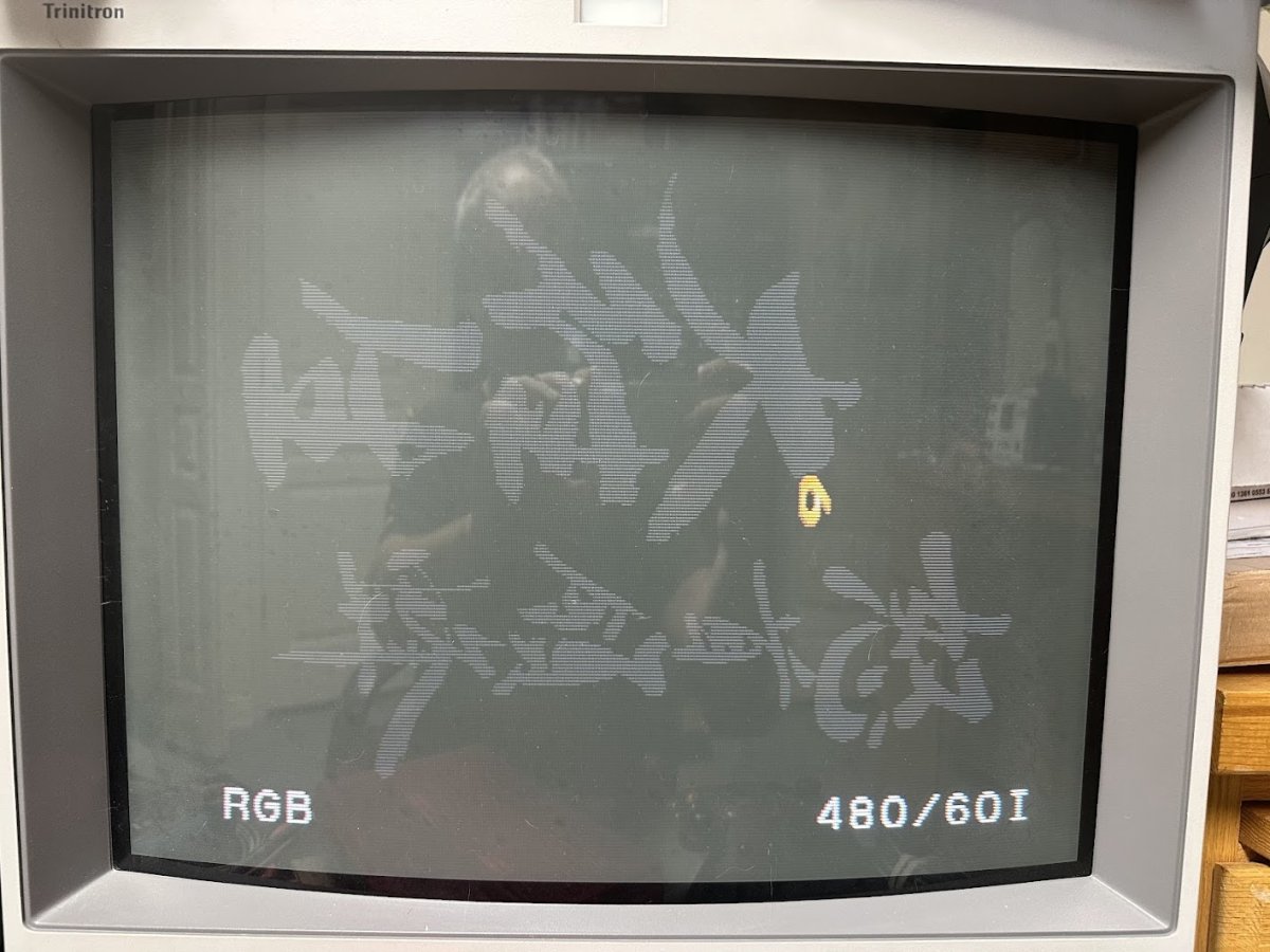
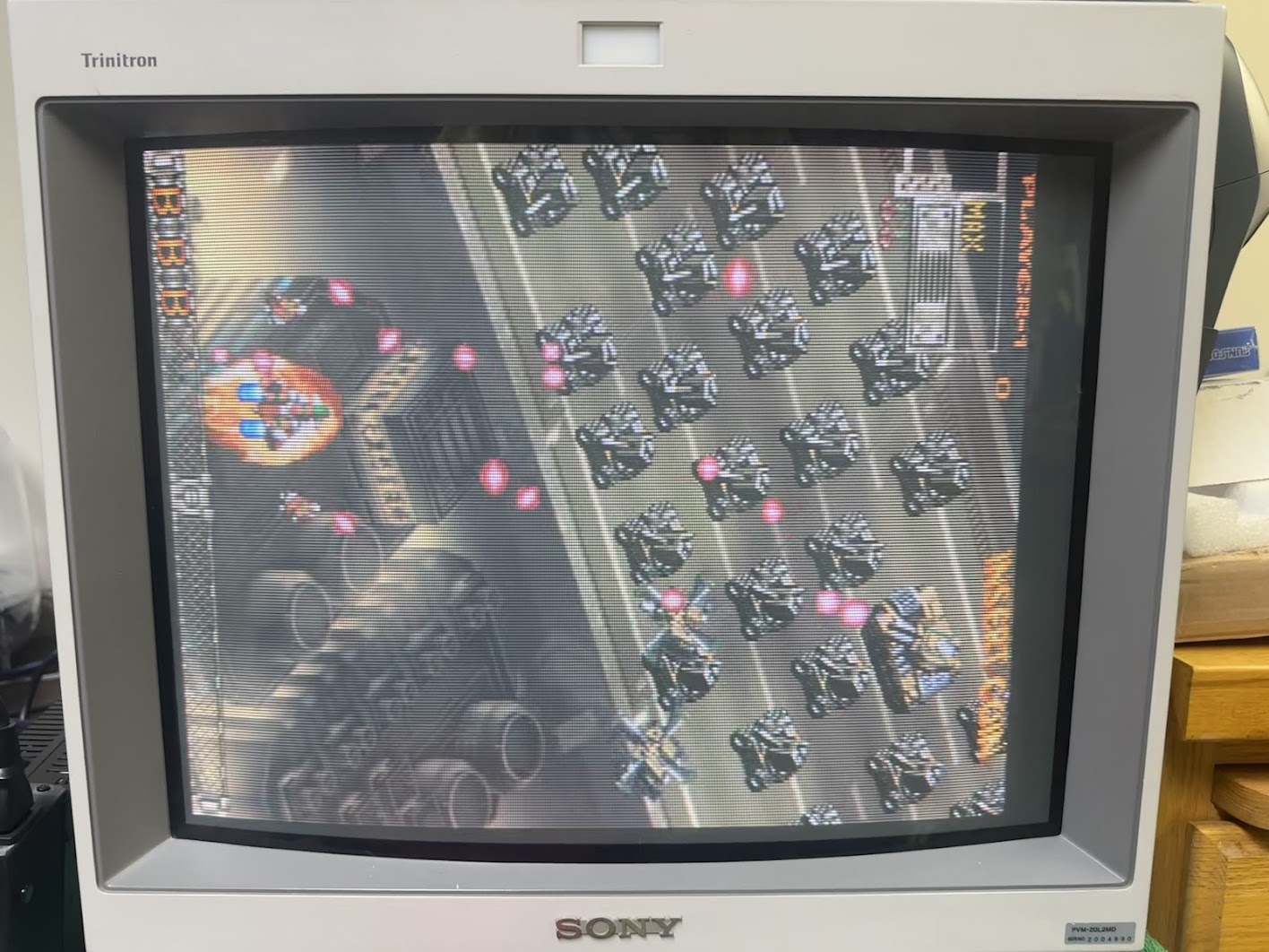
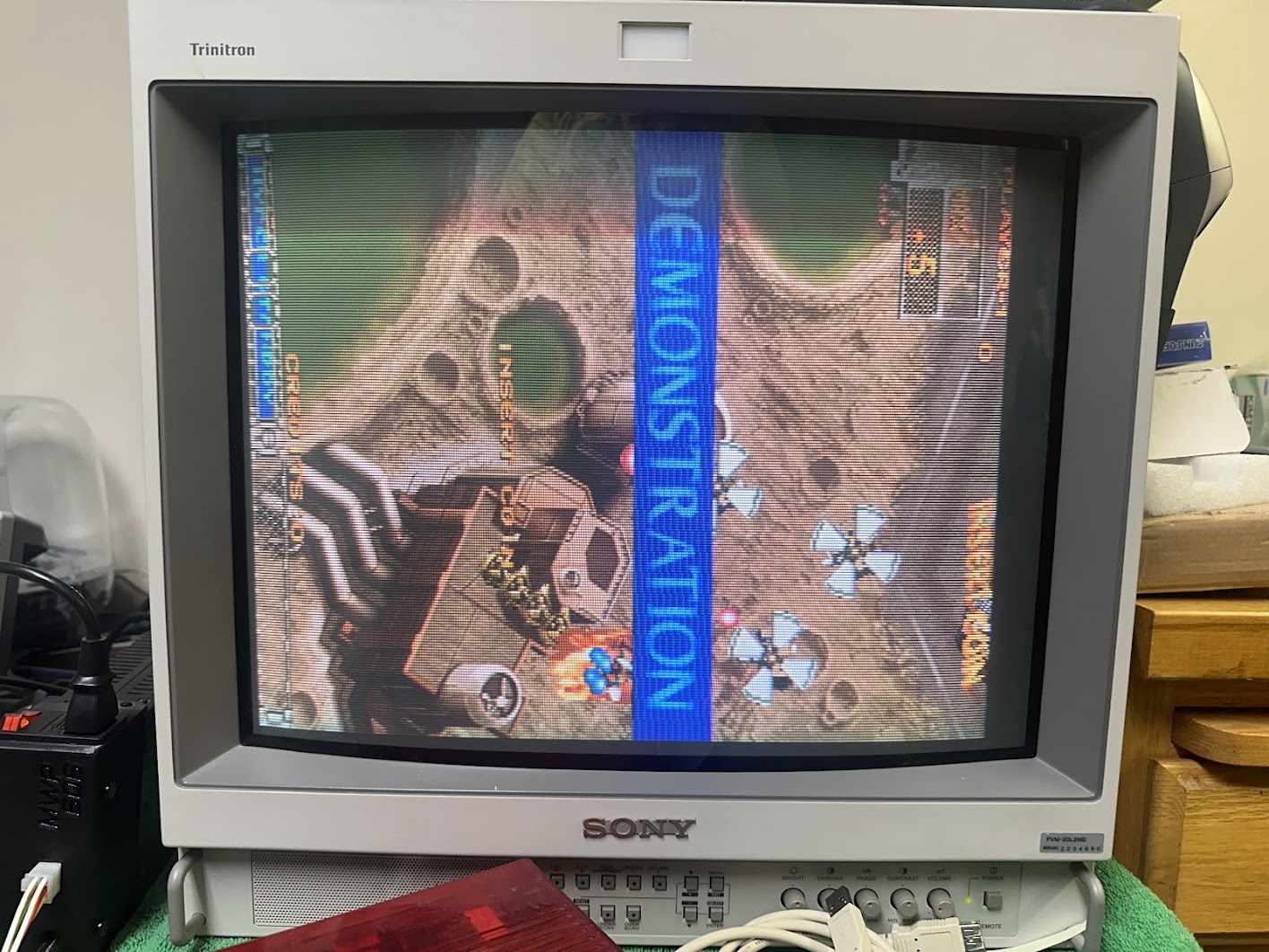
In for repair is a DoDonPachi Dai-Ou-Jou (DDP DOJ) arcade board by Cave. It boots up fine but the backgrounds and most of the text are missing.
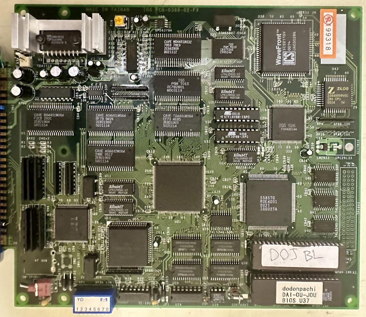
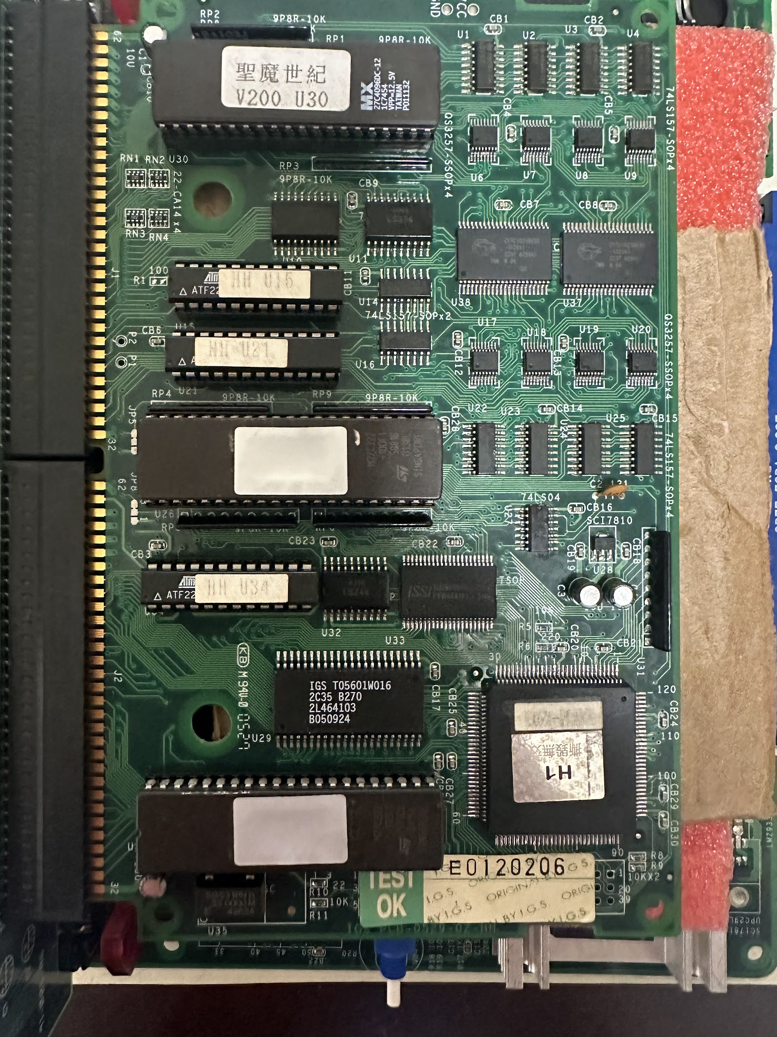
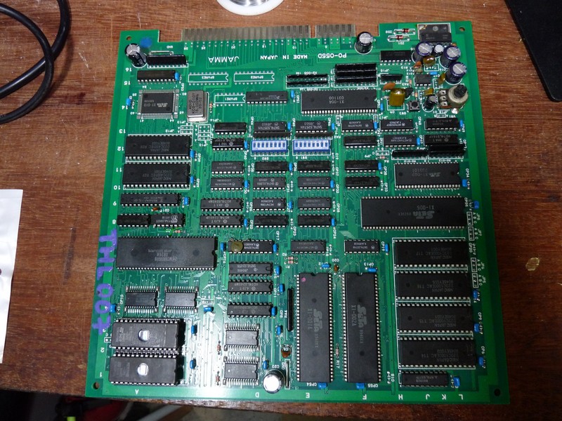
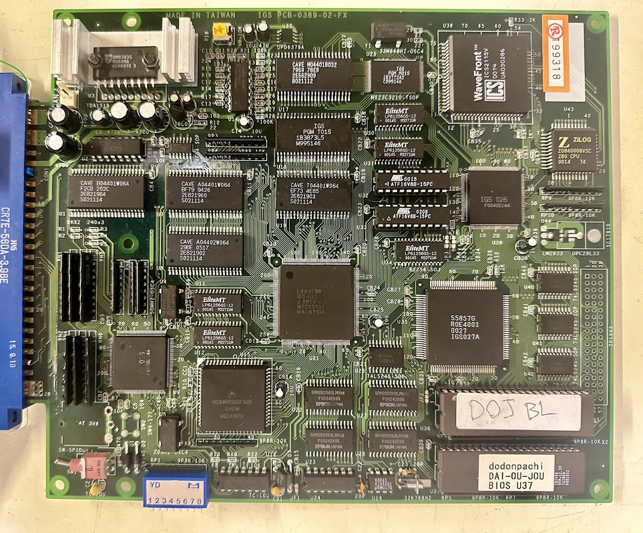
DDP DOJ runs on the IGS Poly Game Master (PGM) hardware. Although DDP DOJ was never officially released as a PGM cartridge, the game was easily dumped from the original stand-alone boards and can then be loaded onto a PGM cartridge.
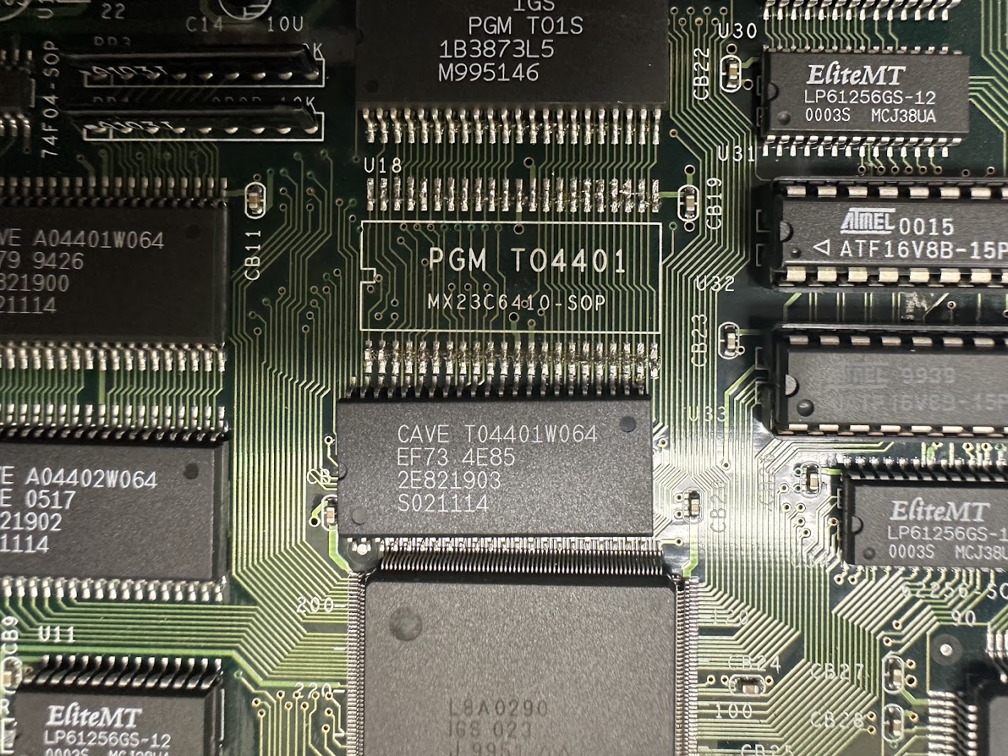
According to the MAME driver for the PGM, two ROMs are involved in drawing the backgrounds – a BIOS ROM and an asset ROM.

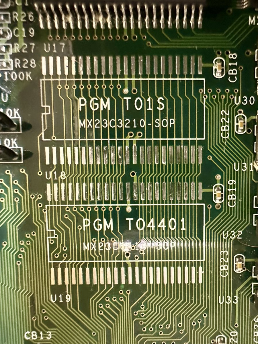
In MAME, I overwrote the “pgm_t01s.rom” BIOS ROM file with all “FF” but the game still booted up and played fine. Overwriting the “cave_t04401w064.u19” file with all “FF” replicated the real board’s behavior in MAME.


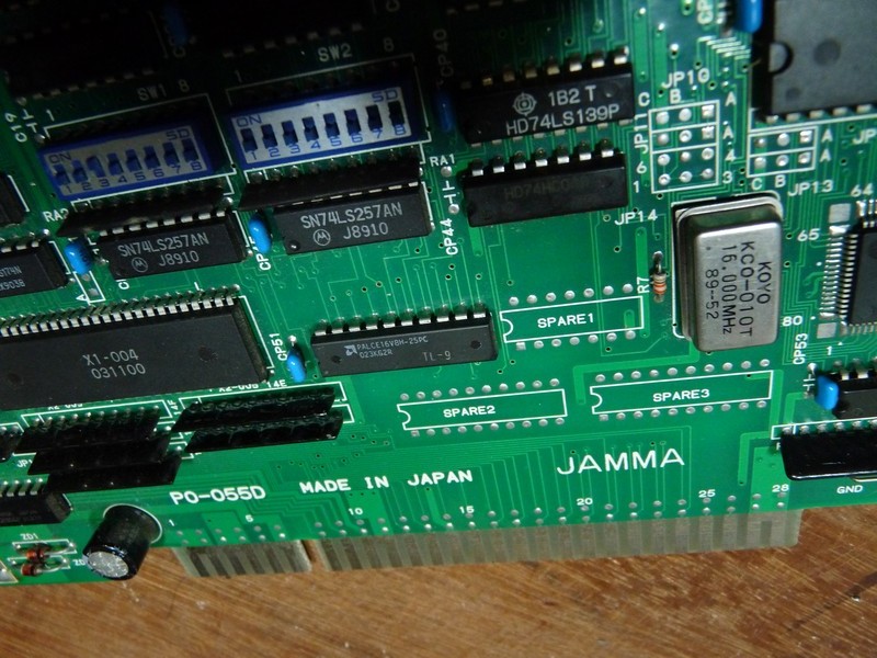
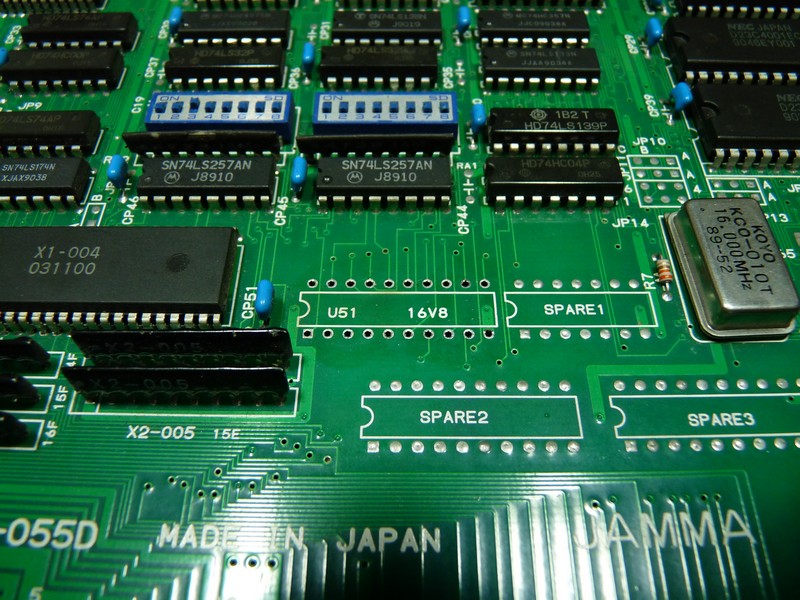
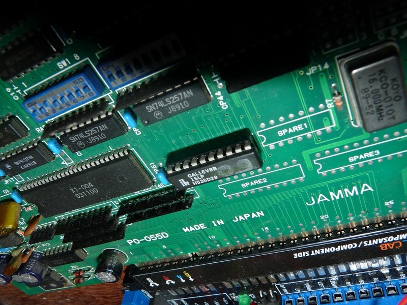
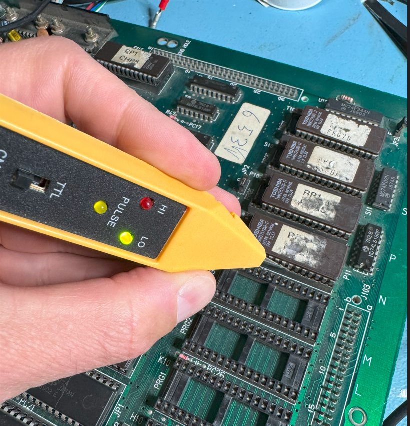
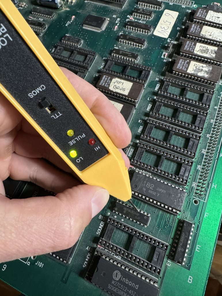
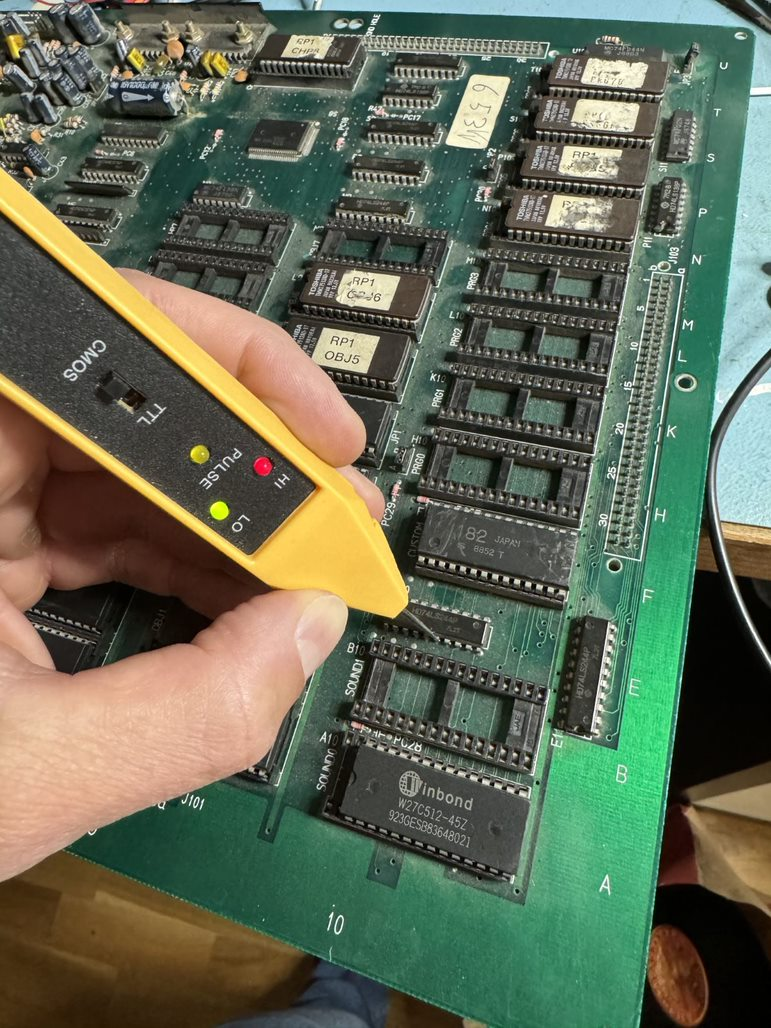
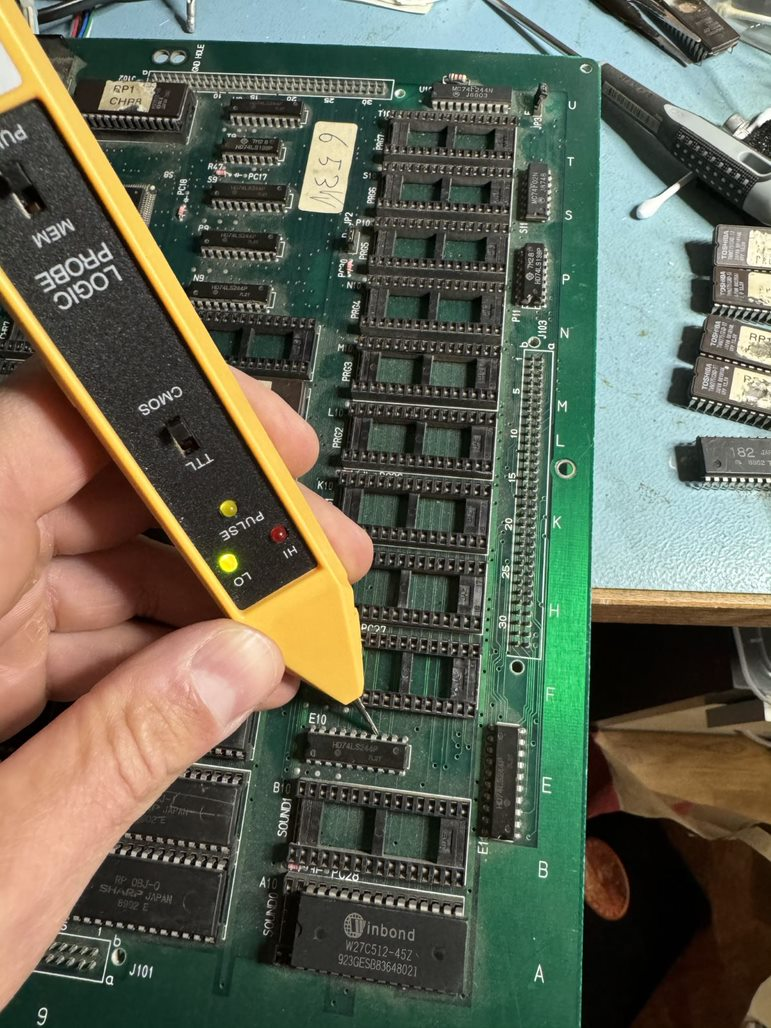
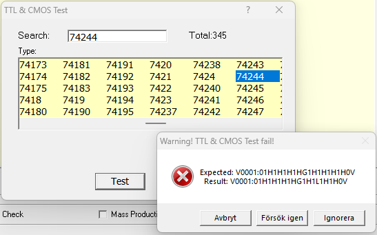
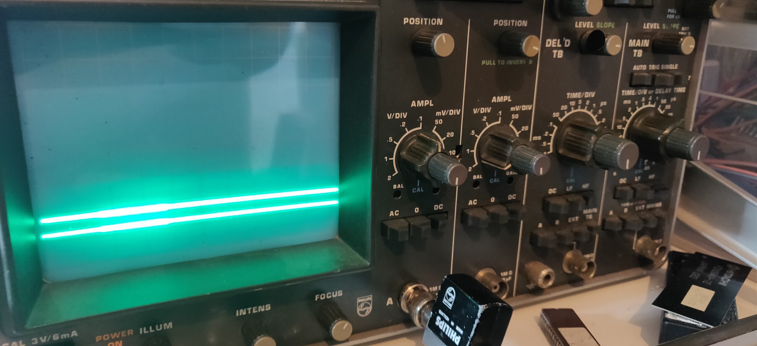
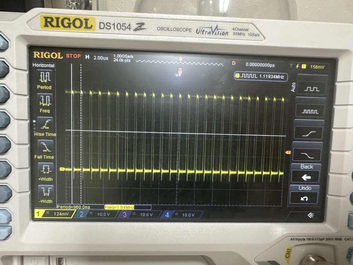
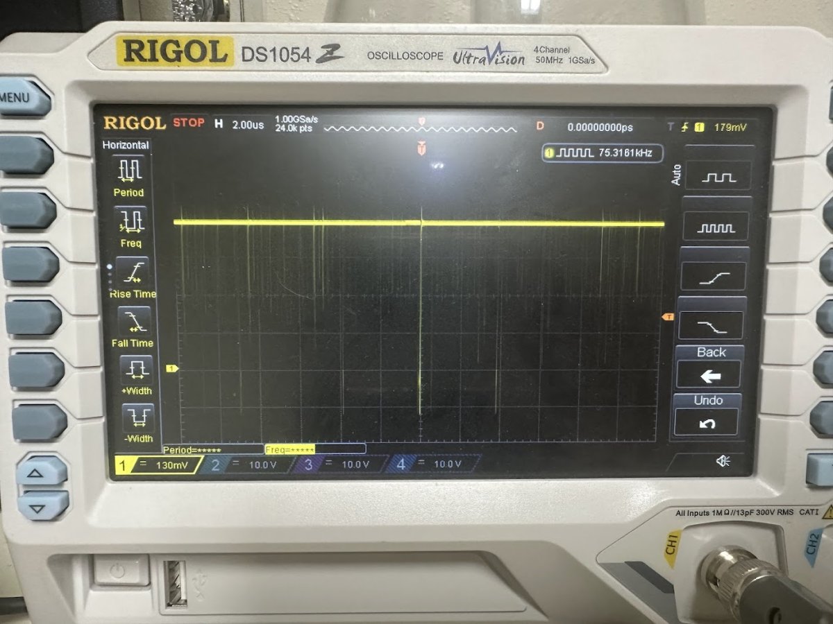
This implied that the mask ROM located at U19 was only reading out “FF”. Probing the address and data lines of that mask ROM on the running board confirmed it – the Address lines would signal properly but the Data lines pretty much always read High.
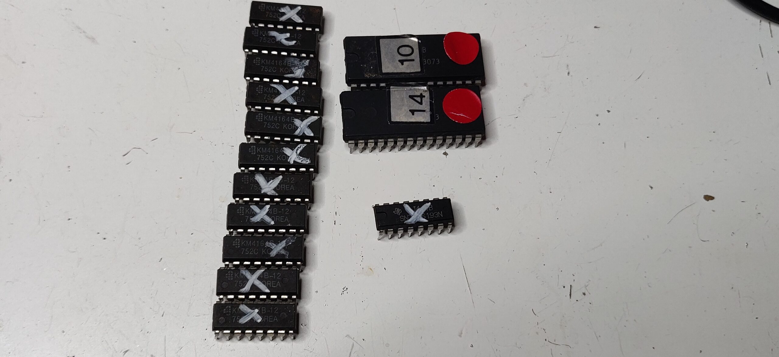
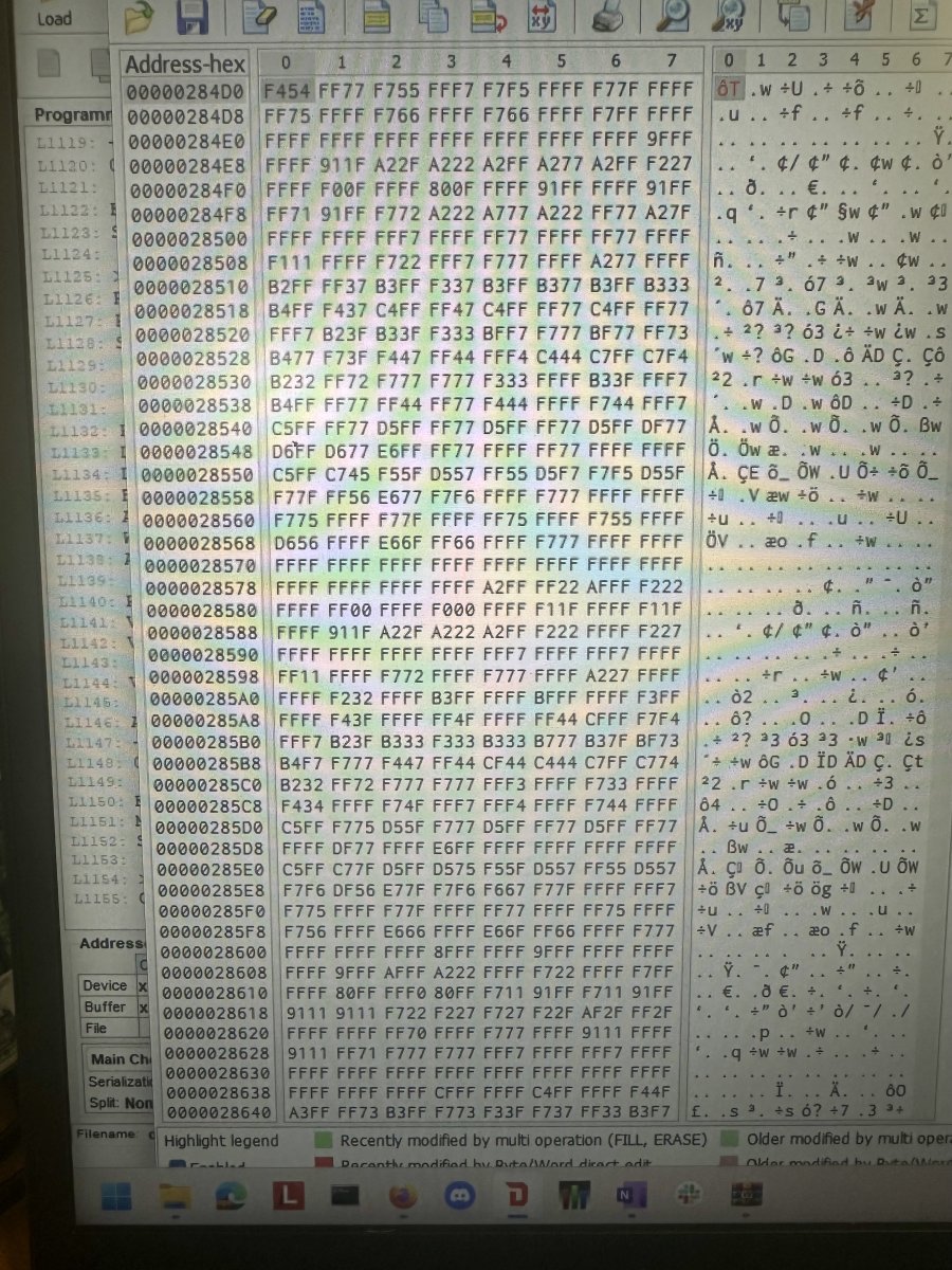
I desoldered both the U18 BIOS ROM and U19 asset ROM chip and attempted to dump them both as a 29F1610 flash chip since that part has the same pinout. The 29F1610 is a 16 Mbit part that matches the 16 Mbit BIOS but is only one-quarter of the 64 Mbit total stored in the background asset ROM. But even with only one-quarter of the background ROM dumped I’d be able to see if data is reading out of the ROM properly.
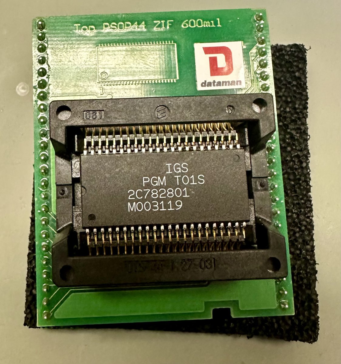
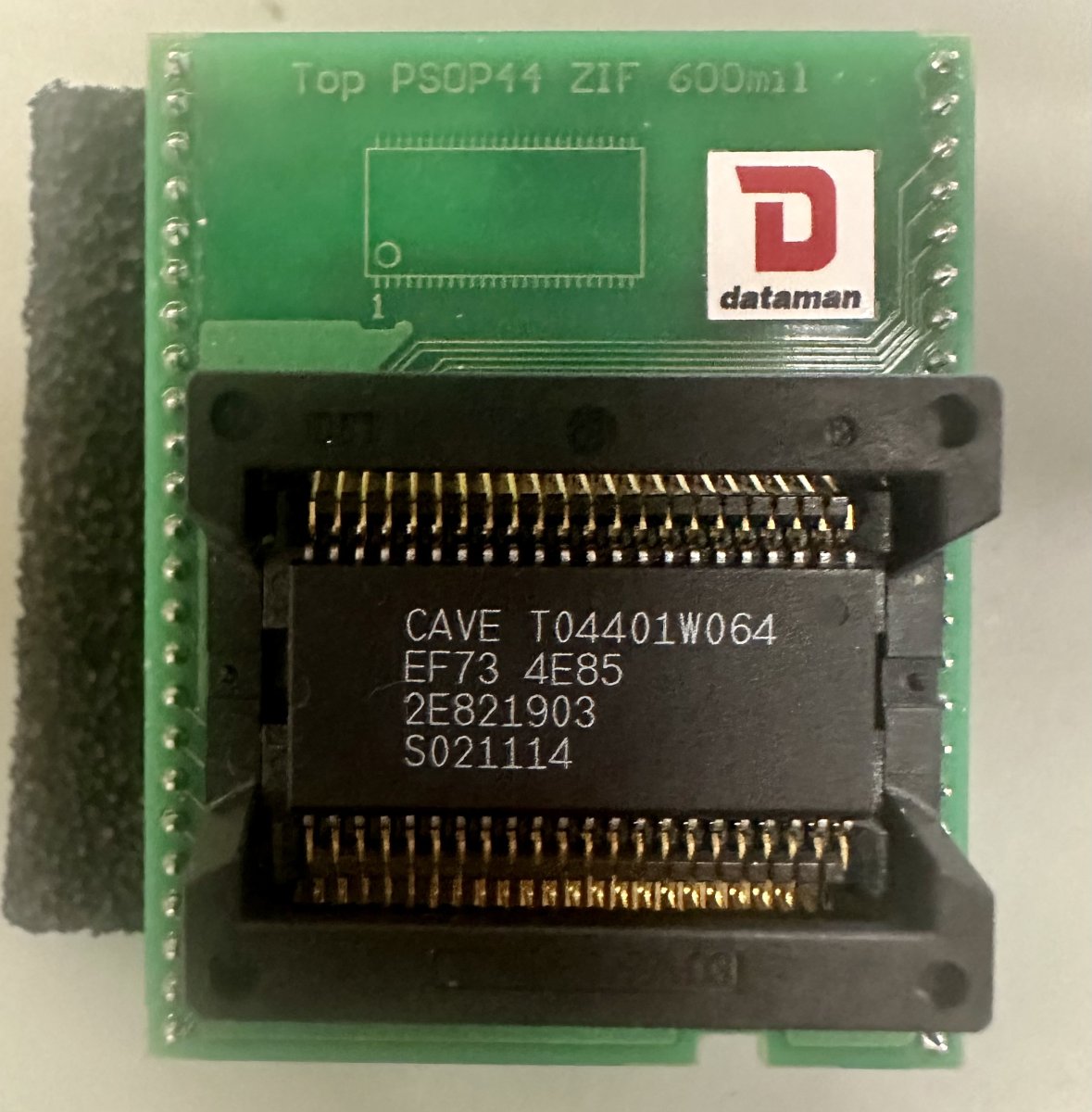
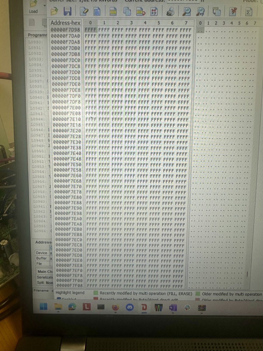
The BIOS ROM successfully reads out data but the background asset ROM only reads out FF – looks like the background ROM is toast.
Now for a dilemma – what to do about replacing a dead DDP DOJ background asset mask ROM? The original part is a MX23C3210 mask ROM. There is not a programmable off-the-shelf part with 64 Mbit capacity and the same 5V voltage that the PGM hardware uses that also matches the pinout and footprint of the original mask ROM.
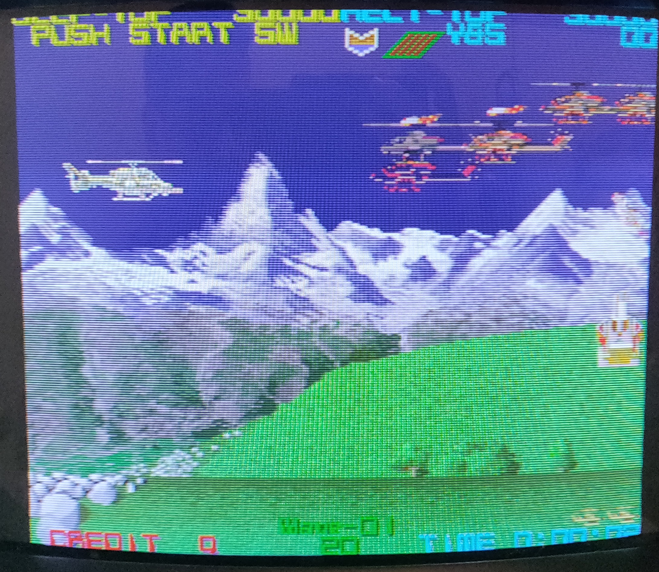
I did prototype a solution that I will describe at the end of this post, but for now I’ll skip to the end of the repair and say that the owner of this board sourced a dead donor PCB of the same game. I was able to successfully transplant the BIOS and art asset mask ROMs from the donor to this PCB and it worked correctly afterwards – a successful repair.
Stepping back to earlier though, while the owner searched for a parts donor, I reached out to colleagues on both the Arcade Projects forums and on Discord for advice for replacing the dead 64 Mbit asset mask ROM. One consideration was to use four 29F1610 16 Mbit flash chips with a 74LS08 TTL chip to drive the Chip Enable lines. A second consideration was to use two 27C322 32Mbit EPROMs – that’s what the PGM cartridge conversions of DDP DOJ use. The drawback to both of these approaches is that the substitute chips would take up a lot more physical space than the original mask ROM so attaching them to the board would be challenging.
A third consideration that I proceeded to prototype with was to adapt an Intel DA28F640 flash chip. The DA28F640 is 64 MBit capacity, 5.0V compatible and programmable but it has a completely different pinout and footprint. I’d never created my own circuit board before, and this seemed like a great opportunity to learn KiCad. Over a few evenings, I referenced data sheets, took measurements, and produced an adapter board.

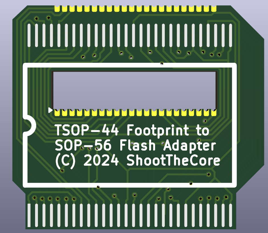
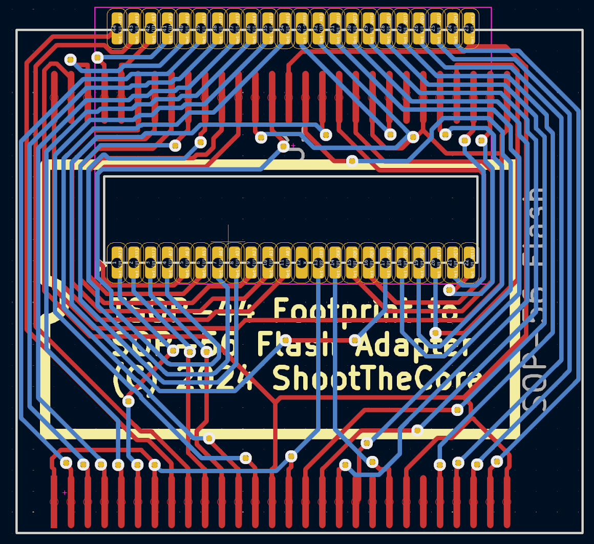
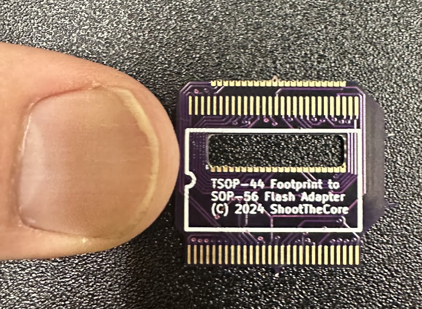
By the time the production adapter boards arrived, the game had already been fixed with the mask ROM from a donor PCB so my adapter is untested for now. Hopefully I’ll get a chance to try it with a different repair.
Here are the data sheets of the parts involved in this repair, along with the KiCad project files for the flash adapter PCB. If you use this adapter for a repair, please let me know if it works for you!
MX23C3210 mask ROM datasheet
Intel 28F640 pin assignments datasheet
Intel physical footprint datasheet
Flash Footprint Adapter KiCad files (Currently Untested)