I grabbed this little fella from eBay not too long ago for very nice price although it was sold as having vertical collapse on the screen.
As it happens this was a complete lie but it is eBay so I should have known better.
On powering up I was greeted with nothing. No ‘Vectrex buzz’, no noises of any sort, nothing!
Getting the easy stuff out the way first I checked the plug fuse. All OK in there.
Time to open it up and see what we can see.
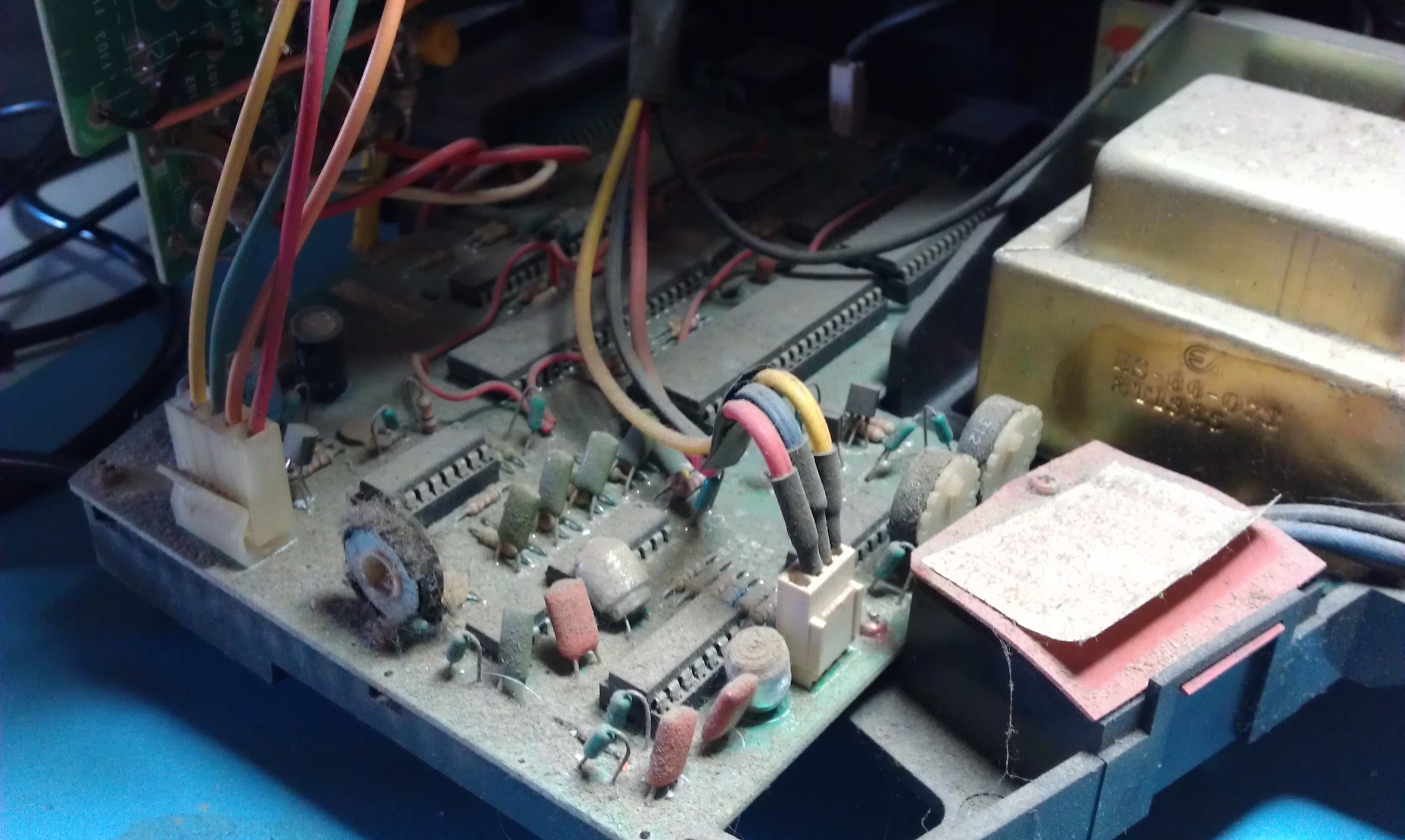
I saw dust, and lots of it.

Let me take a moment to explain a little something about the Vectrex. The picture above shows the logic board in its housing. In the Vectrex it is not just a matter of removing a couple of screws and taking out the board. Everything is connected to everything and sometimes not by means of plugs either, they are soldered in there so removing the logic board took a long time and a lot of pictures were taken of various wire locations and a lot of tiny screws were removed.
I checked voltages at the transformer and got 240v. I checked the output of the transformer and got nothing. Problem #1 found.
The transformer is a standard 9-0-9 VAC type and I bought a replacement from Maplin (thanks to Mesmeric_G from UKVAC for pointing me in the right direction).
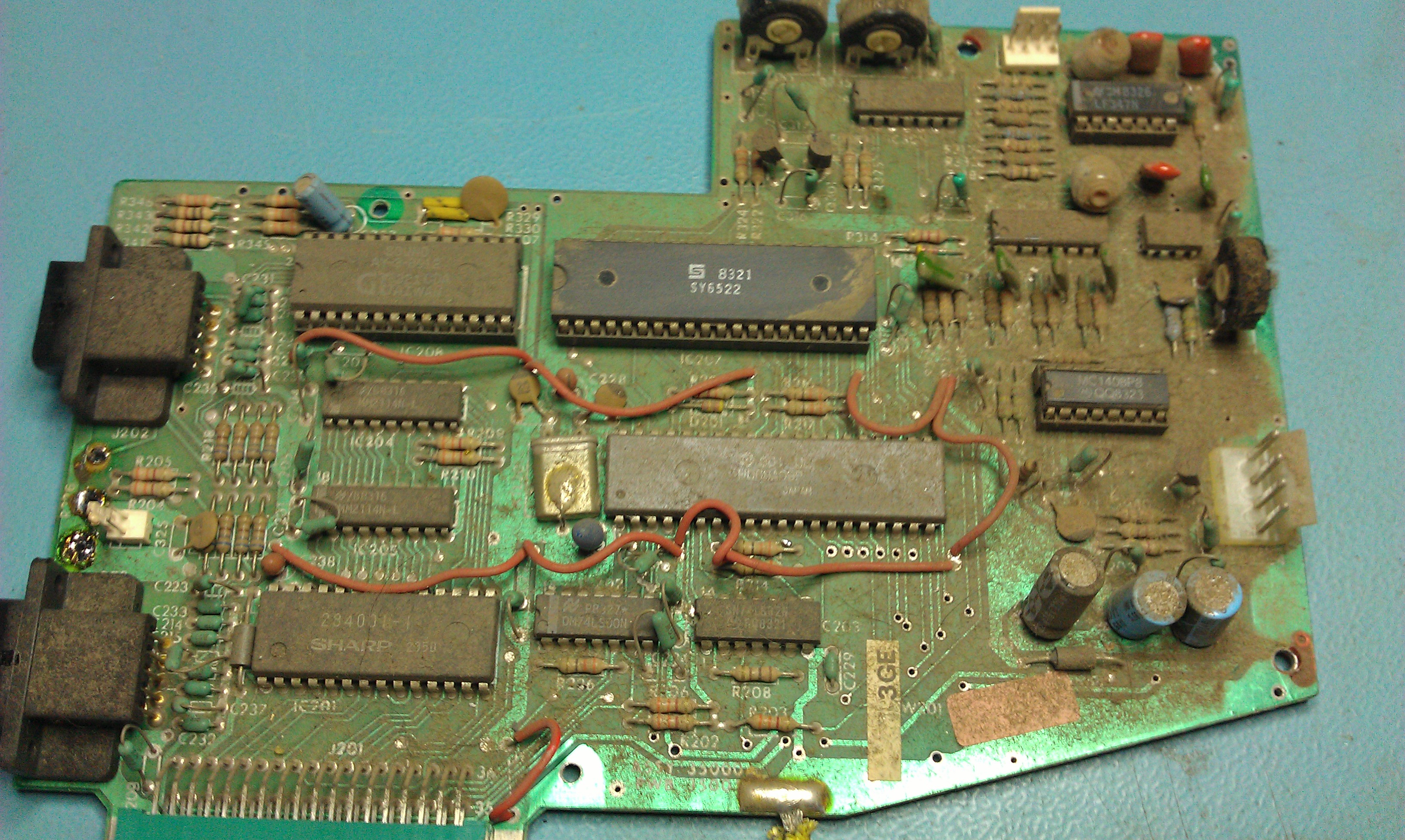
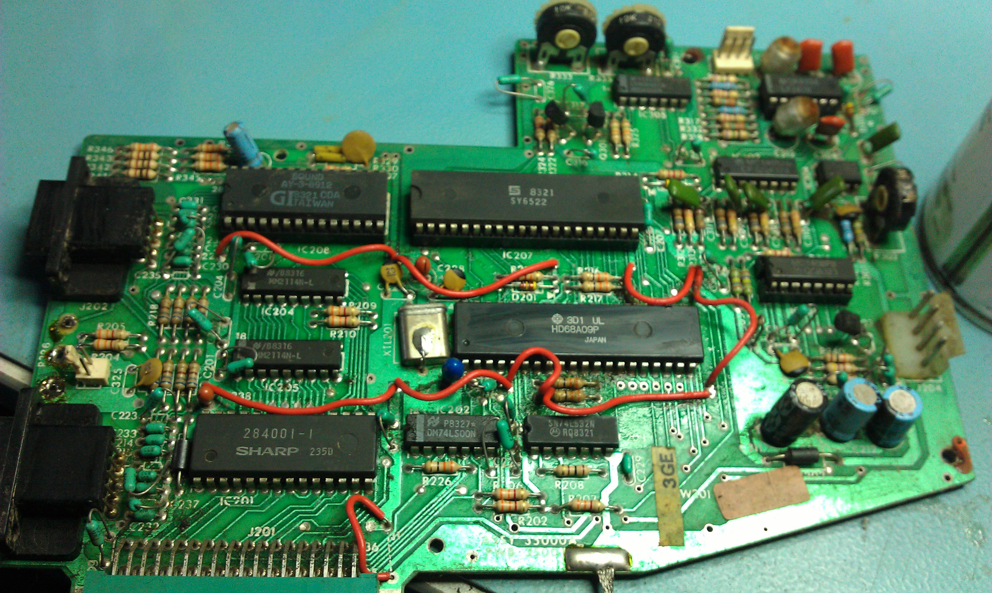
In the mean time I set about cleaning this logic board down.
Whilst the board was out I tested the on/off/volume pot, this checked out OK (but more on that later).
So a few days later the transformer arrived and I went about fitting it. Once everything was in position to test I fired it up and…….nothing!
Turns out my on/off/volume pot is a little temperamental on one of the power lines and will occasionally give a poor connection causing the voltage to drop to around 4v. As a temporary fix Ive hardwired the line in the ON position and am using the plug as a means of turning it on and off. As Im unable to find a suitable replacement for this switch I will probably add a DTSP switch at some point in the future to control the ON/OFF function.
So now Ive got a booting Vectrex with sound.
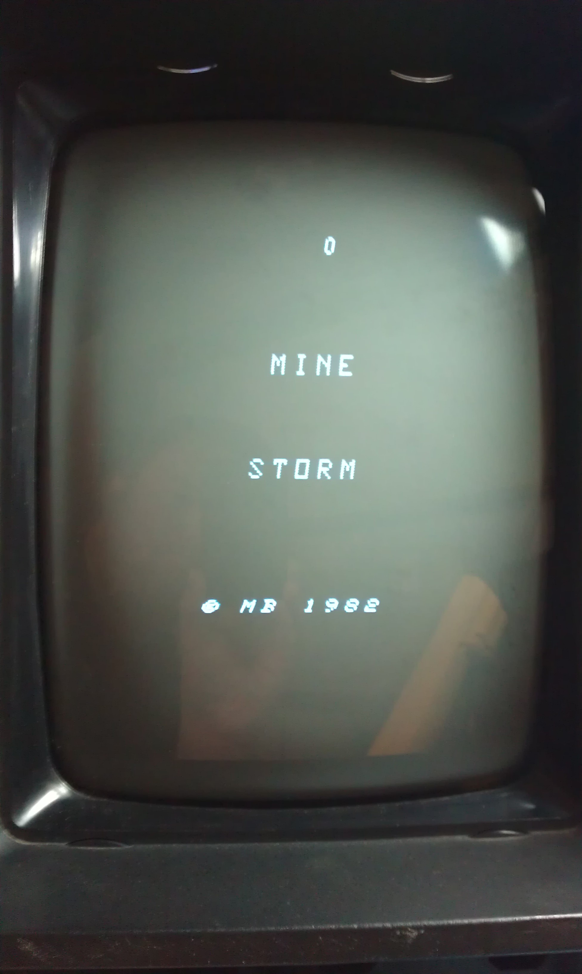
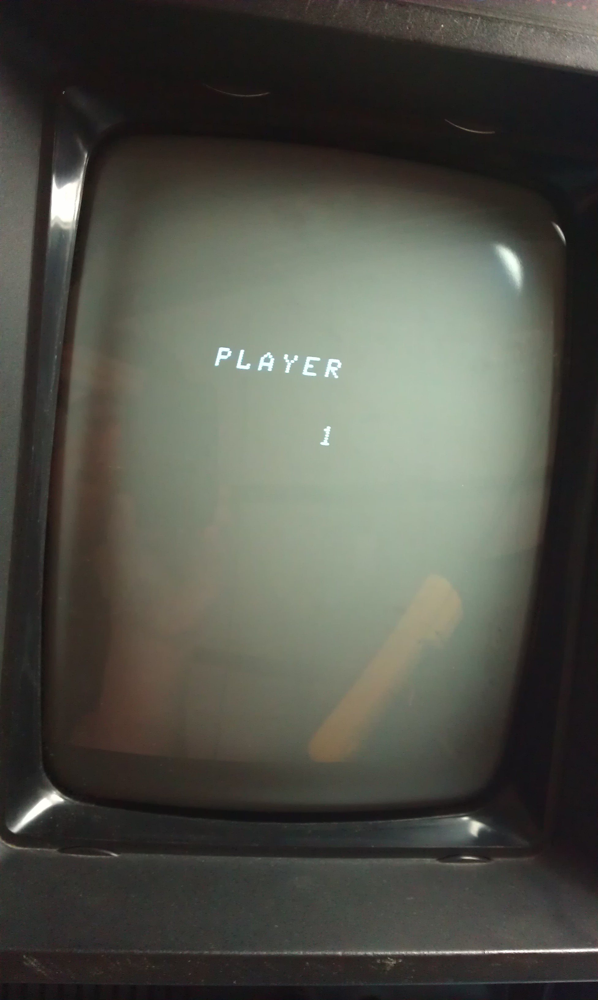
Another problem now. It boots straight into the Mine Storm game that’s built in.
I know for a fact that there is a Vectrex boot screen that should appear first. The game also doesn’t respond to any of the controls and it locks up when it displays “PLAYER 1”
Looking at the schematics that are floating around it looked like the sound chip is also responsible for dealing with the controls.
The chip in question is an AY-3-8912. This chip is socketed so removed it and fired it up.
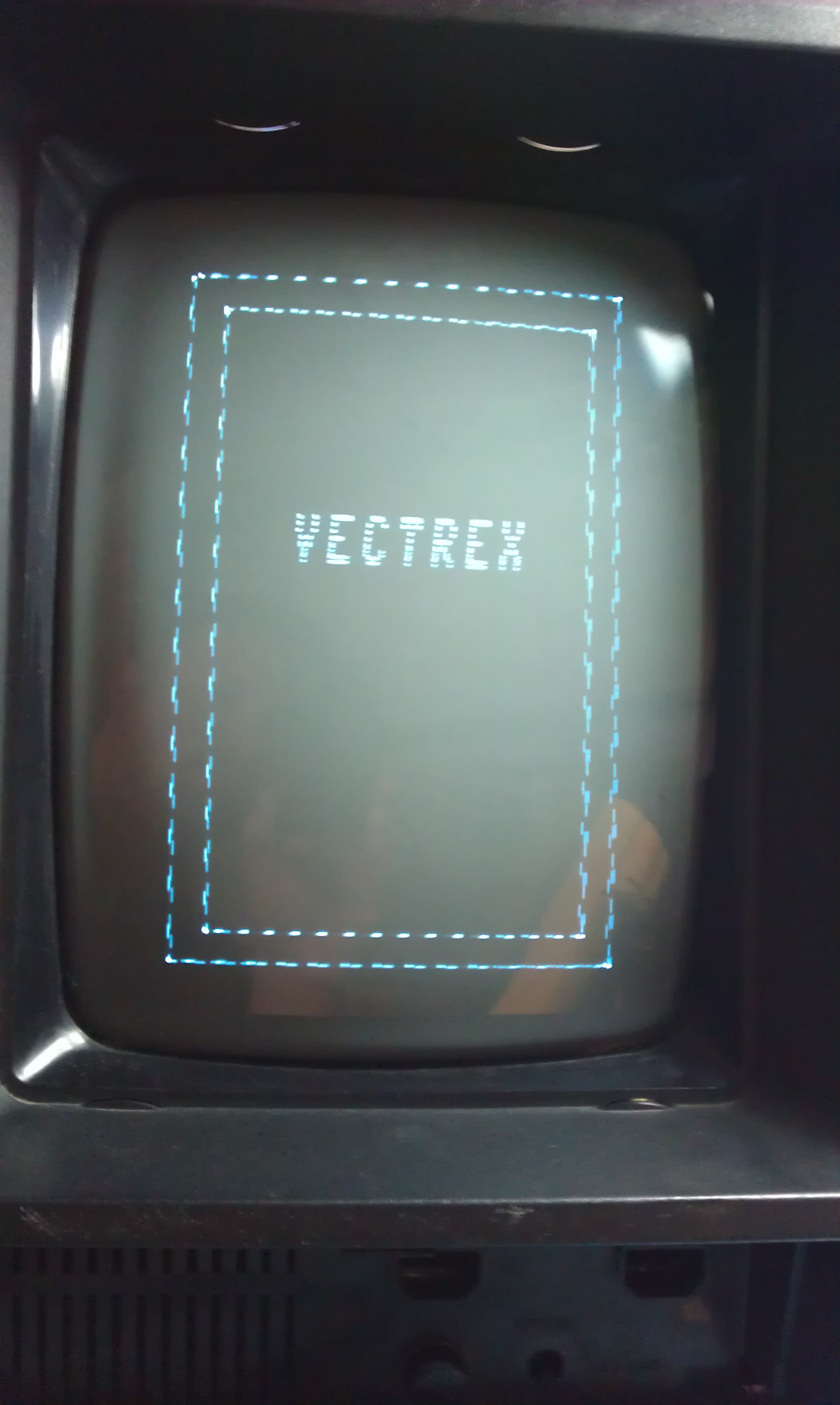
The Vectrex logo is back but I have no replacement chip to use in this yet so that’s where this log will end for now.
I’m positive that’s the only problem left now so will try find a replacement chip somewhere.
Thanks to Phu from the RetroComputerMuseum for his advice. His knowledge on the Vectrex is unsurpassed.