Welcome to my first repair log!
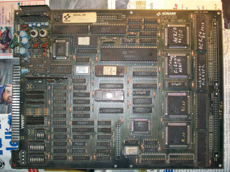
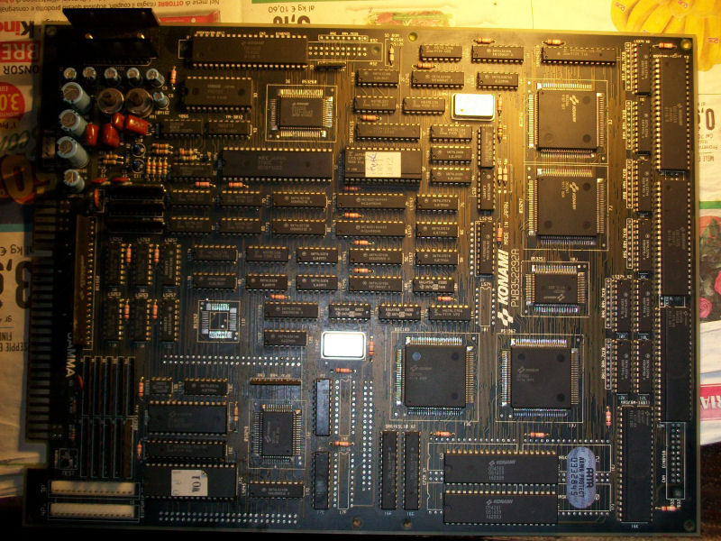
I bought this (very) expensive pcb from ebay in October 2014.
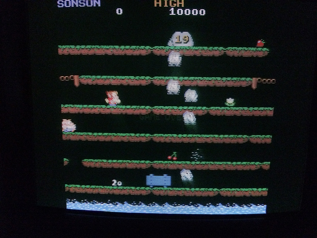
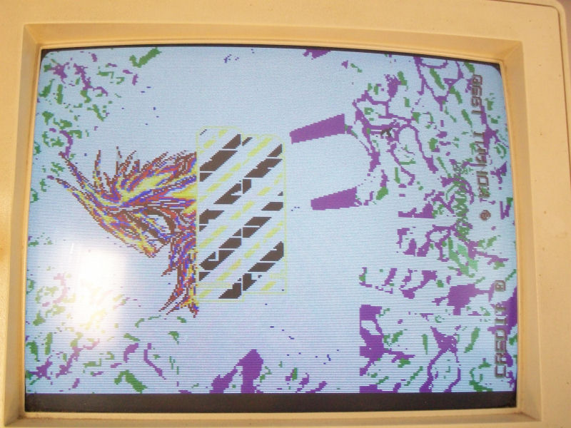
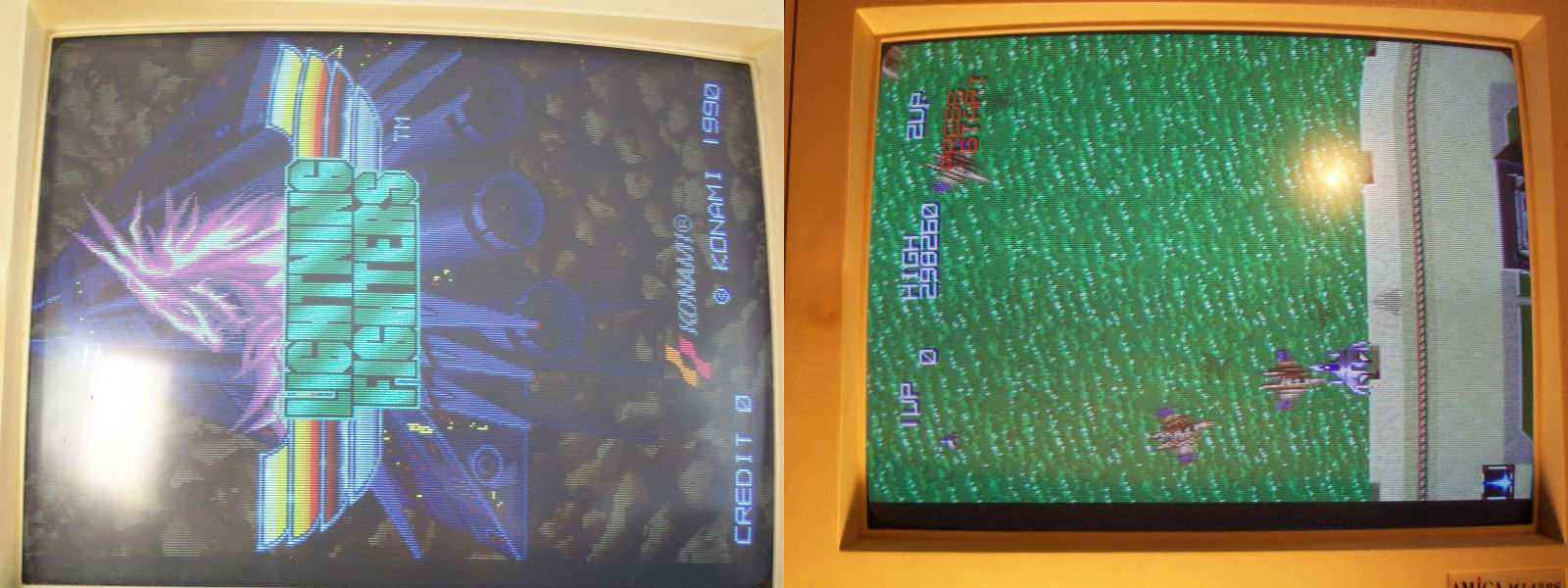
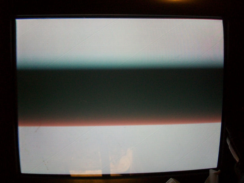
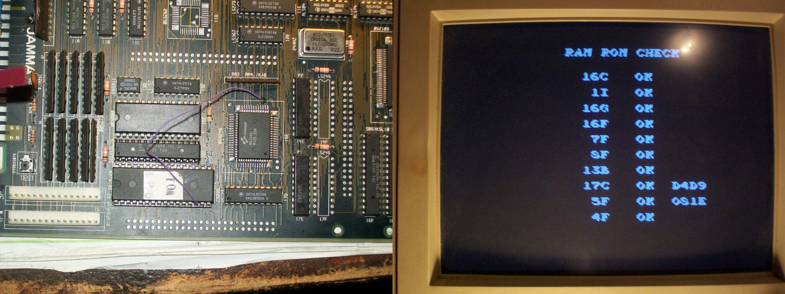
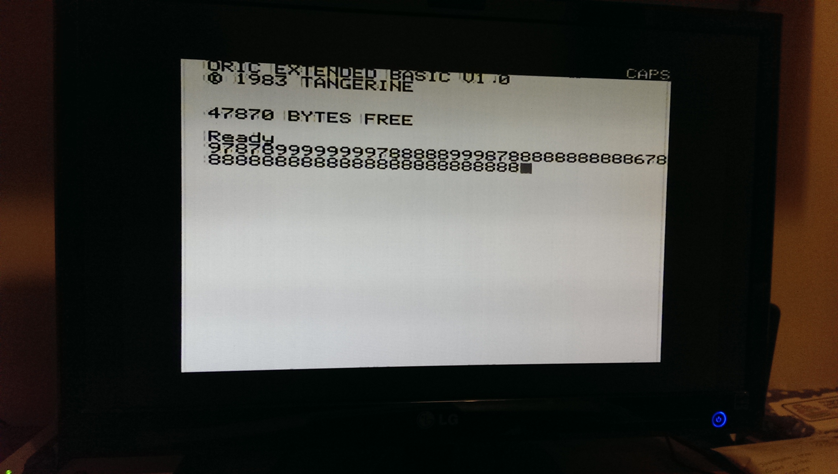
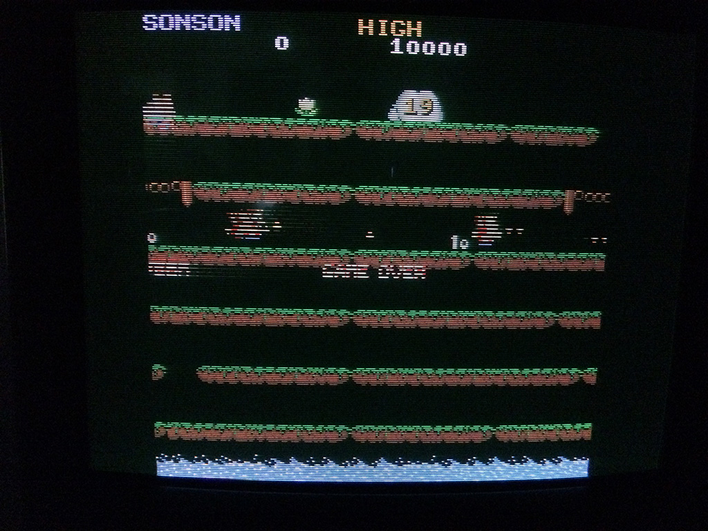
I played the game a couple of times and then after about one week, all the sprites disappeared while I was playing. Only background and text were present:
I couldn’t believe, at first I began to press everywhere hoping it was a loose or oxydized connector but soon I realized something got faulty.
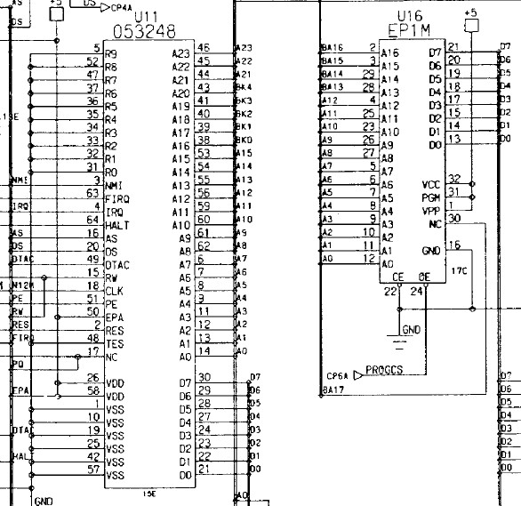
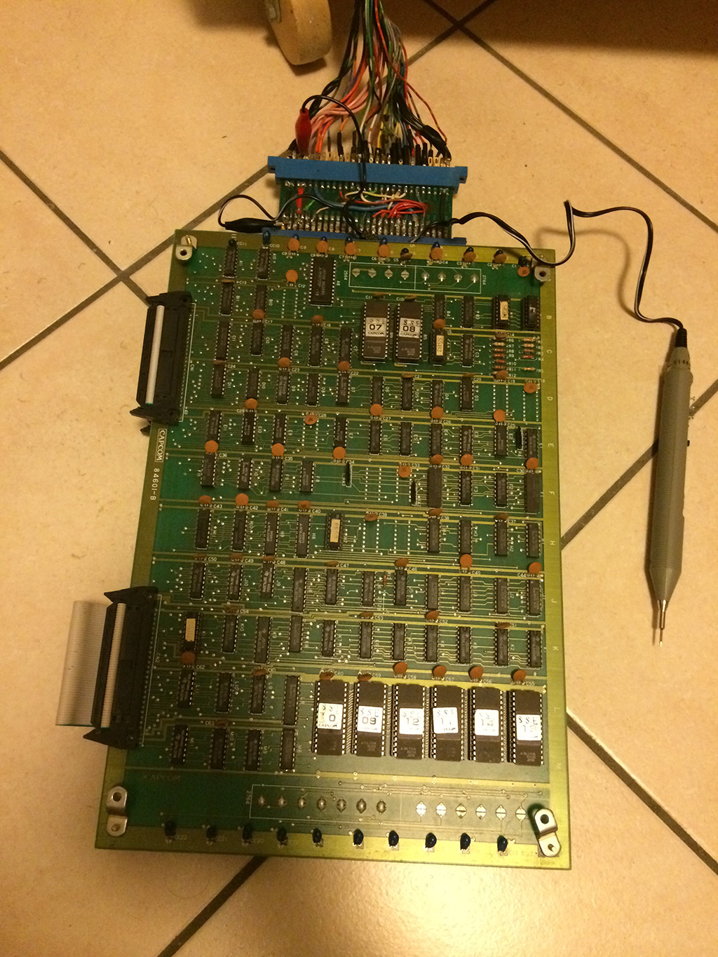
This game hasn’t any schematics available so I knew from the beginning it would have been very tough to fix it.
I connected my trusty logic probe and began to short some pins on the pcb to see what changed on the screen so that I could focus on the right part of the circuit.
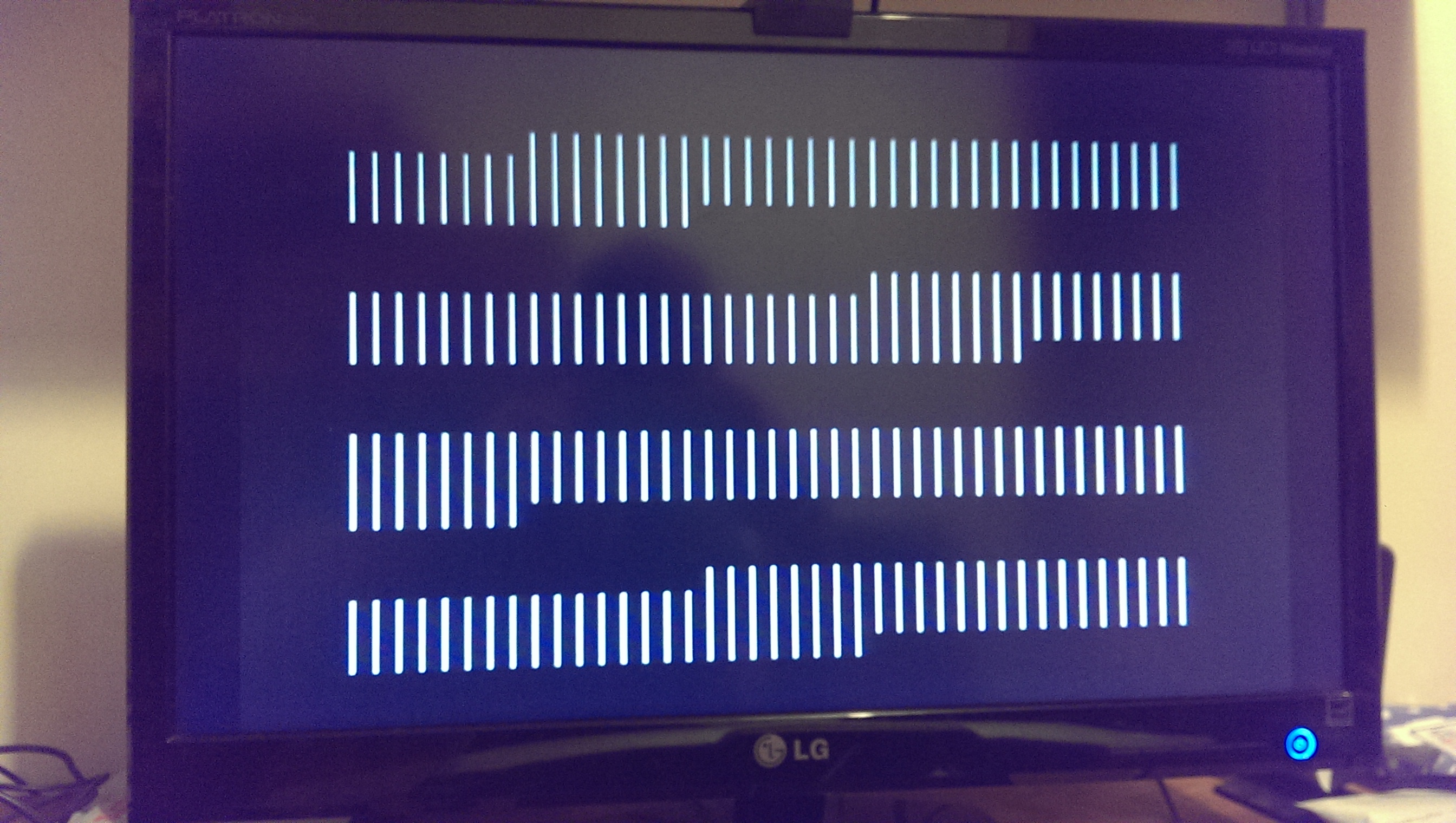
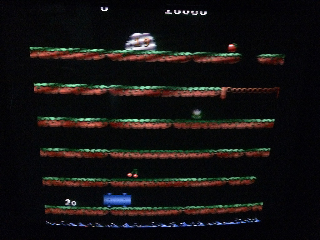
After about 30 mins turned on, the sprites started to reapper but missing some lines:
I then remembered that 1942 hardware is very similar to Son Son and the schematics are available.
I was right, the way that TTL chips are connected on 1942 is equal on Son Son. Only the positions of the ICs are different but the logic is really similar.
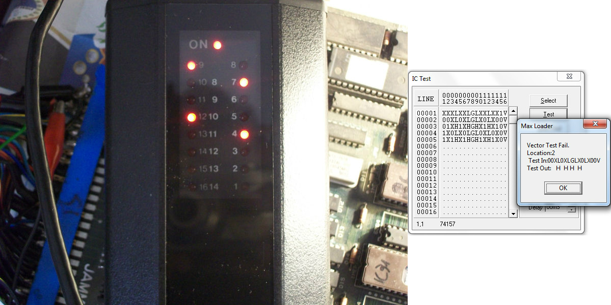
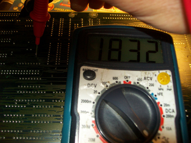
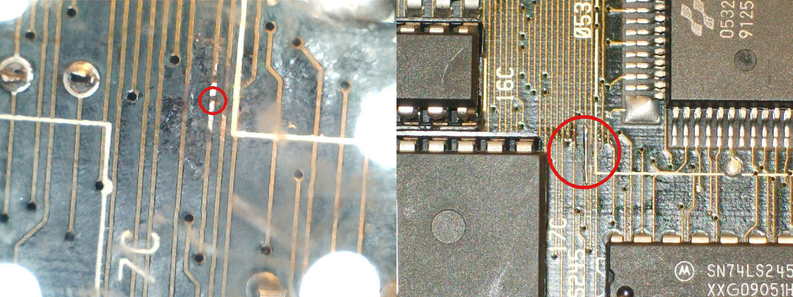
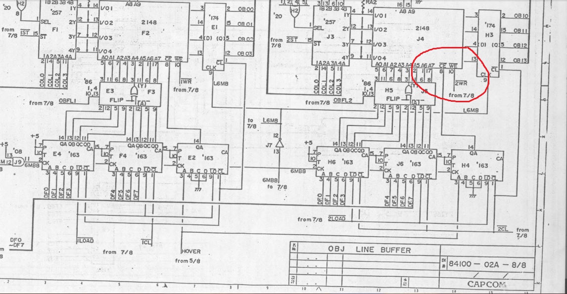
I probed the 2148 rams @F2 and @F4 on Son Son pcb which on 1942 schematics are described as OBJ rams and I found a stuck /WR signal @F4 on Son Son (J4 on 1942):
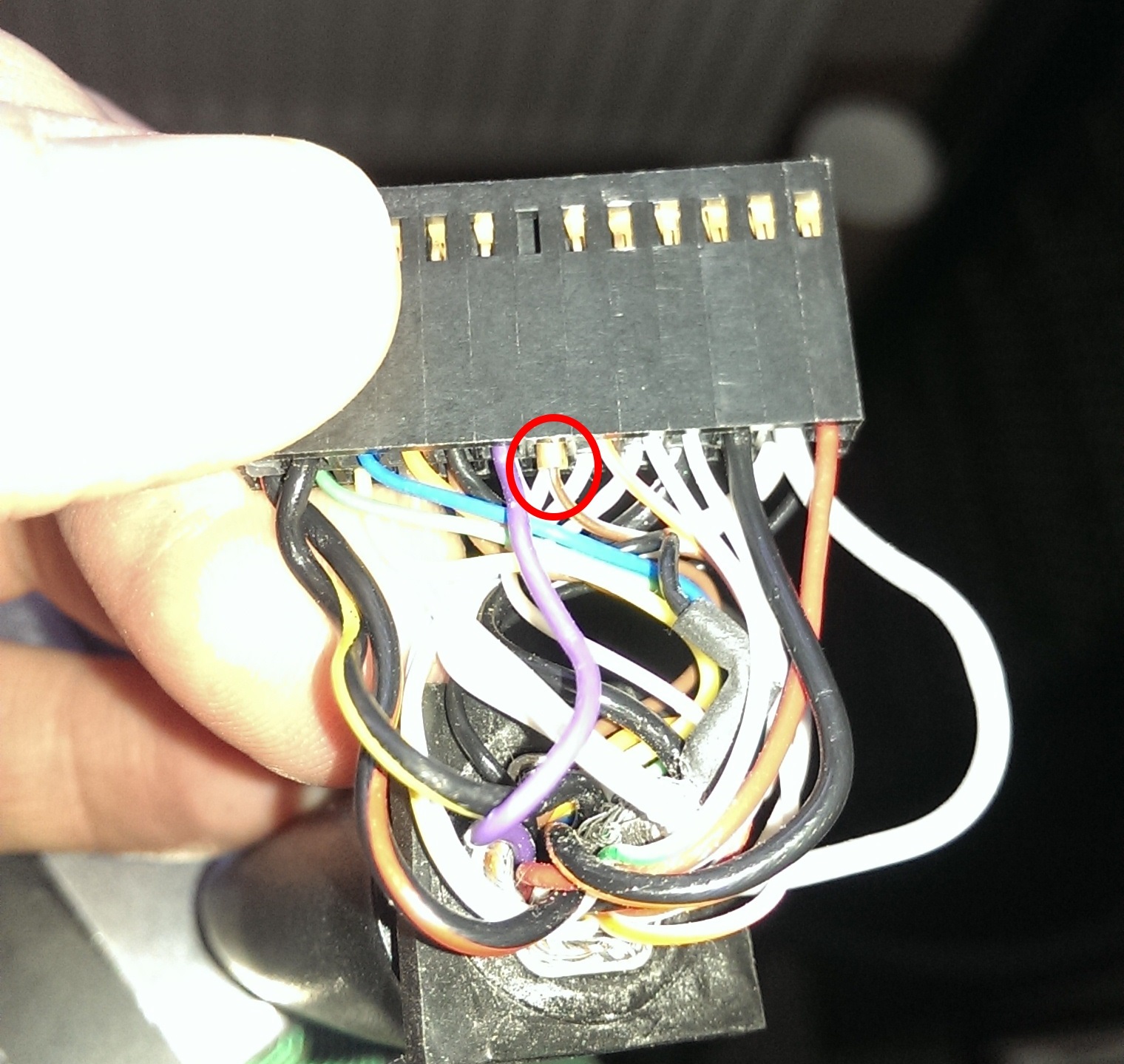
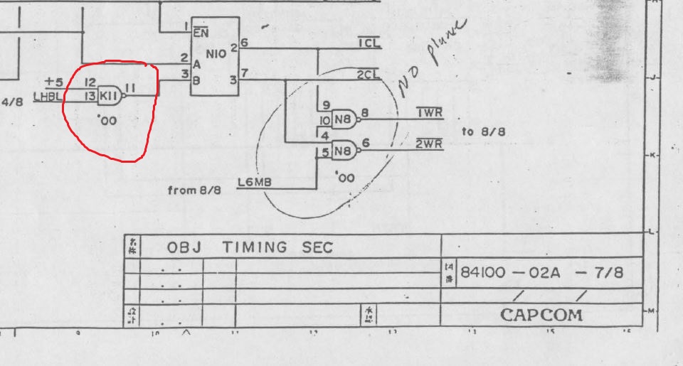
I followed back the signal always taking a look on 1942 schematics, and I found finally the source of the problems on the missing signal on pin 11 of an 74LS00 @F11 (on 1942 I circled the equivalent IC @K11).
On 1942 schematics available on internet, someone circled the 74LS00@N8 writing “no plane”, probably he had the same fault. 😉
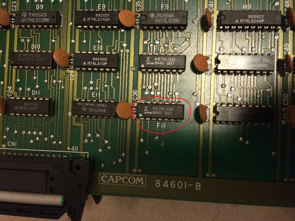
Replacing the 74LS00@F11 gave me back all the sprites