PLS153 to GAL22V10 adapter

 Guides  Comments Off on PLS153 to GAL22V10 adapter
Sep 042011
 

I decided to see if I could replace a PLS153 for a GAL22V10. Due to the high number of outputs the PLS153 has, it cannot be swapped out for a GAL16V8 and GAL18V10’s are a bit pricey. A GAL22V10 on the other hand has enough outputs but it has 4 more pins than a PLS153.
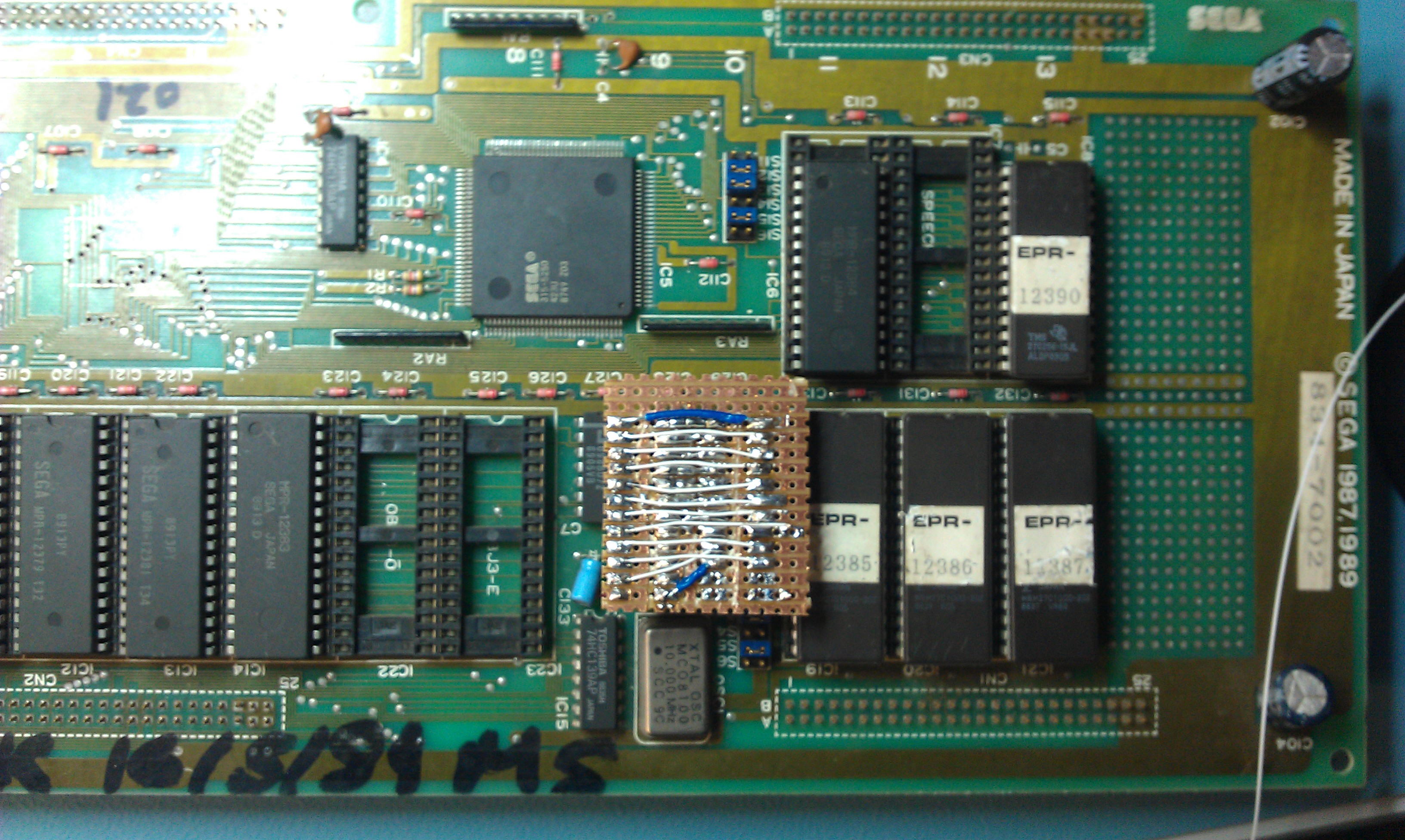
I made a simple (and rough) adapter up on veroboard, reversed the PLS back into equations using a tool made by Charles MacDonald, rejigged the output pins and recompiled for a 22V10.

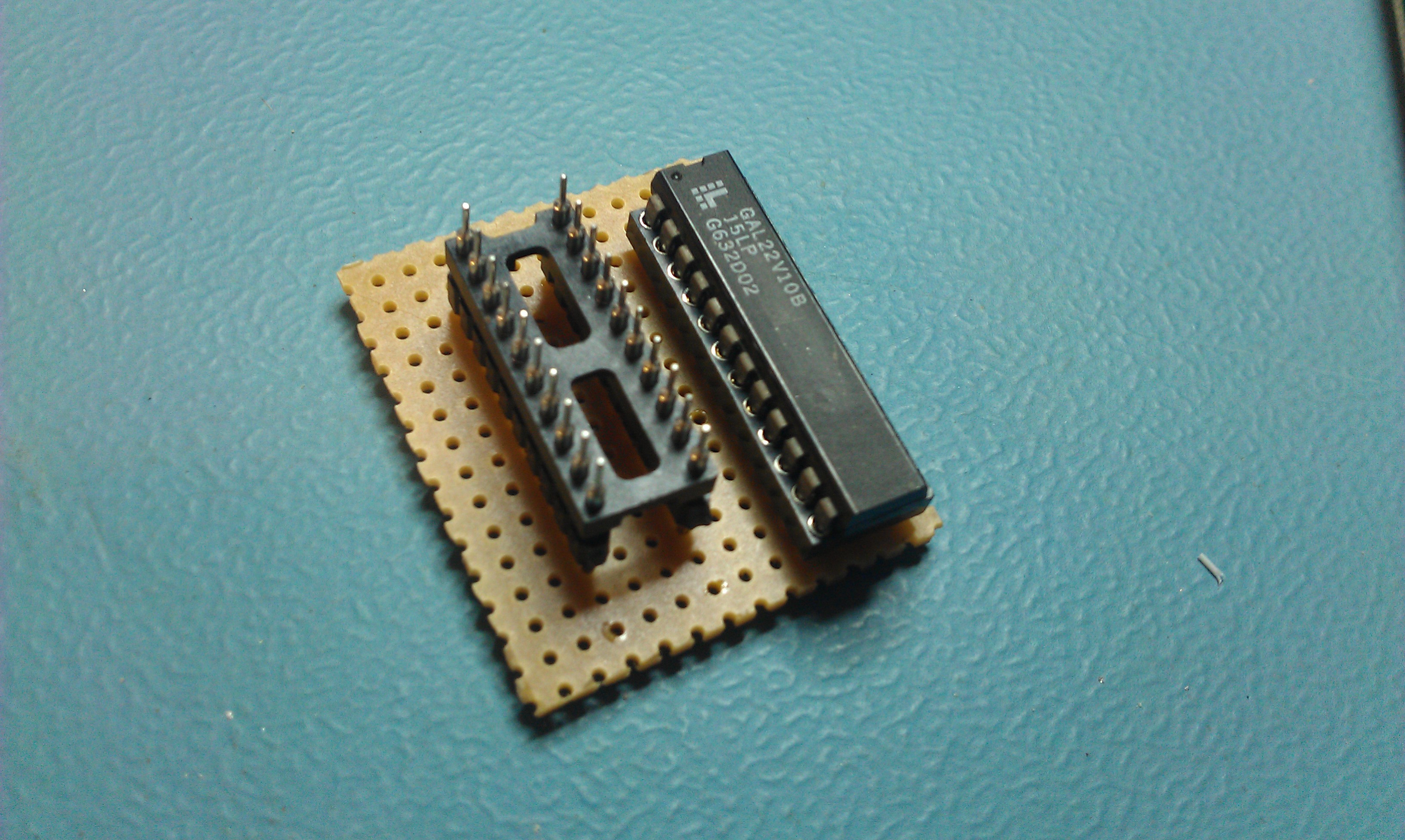
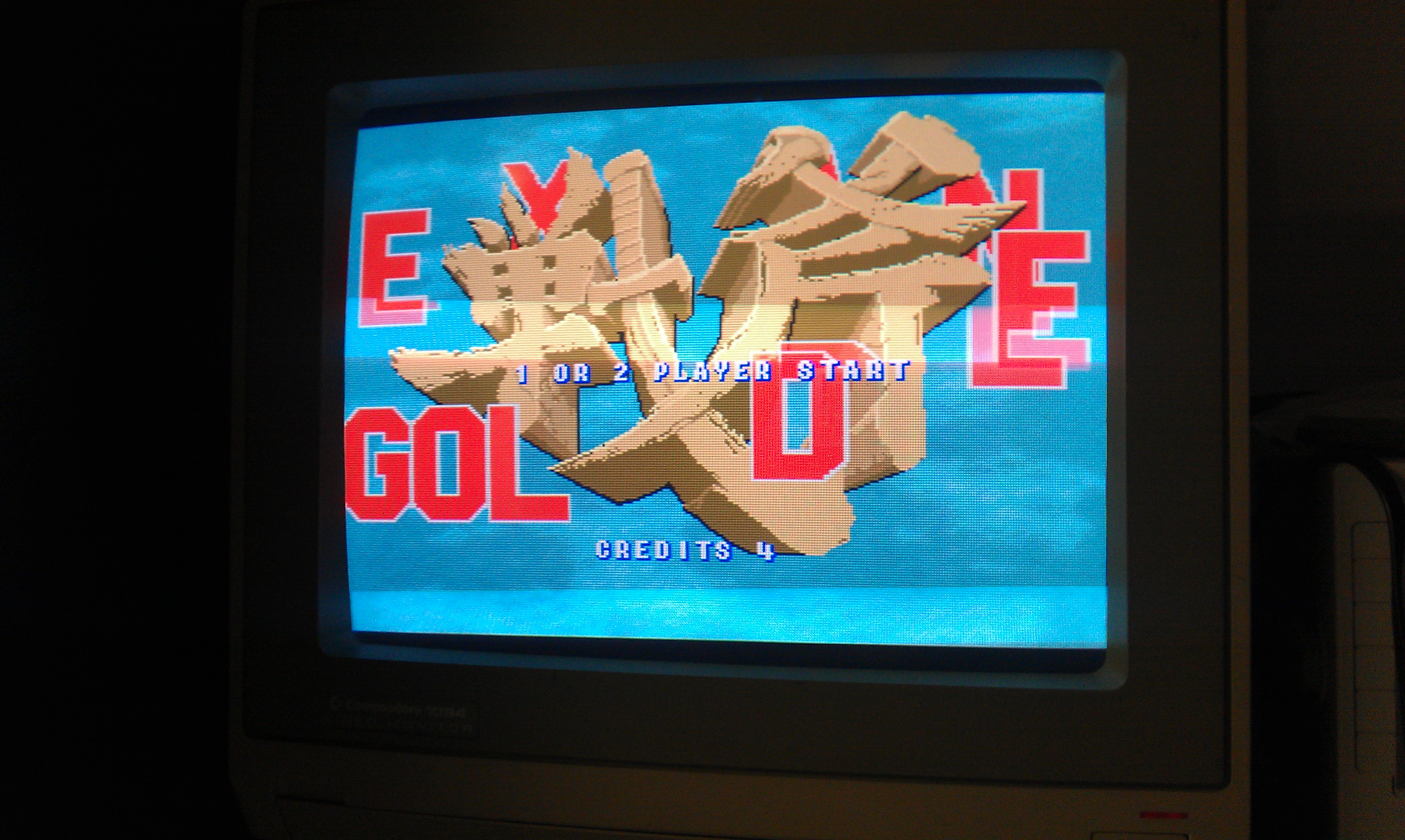
The outcome was a fully working adapter to swap out an expensive PLS153 for a cheap 22V10 and can be made in around 15 minutes.

If anyone is interested in making one of these up that works for my GAL files here is the pinout
NOTE: If you do make one up, remember that you will be turning the adapter around to insert it therefore pin 1 on the PLS side will go to the left. I didn’t think it through on my first attempt and got them the wrong way round.

GAL Pin             PLS Pin
1                       1
2                       2
3                       3
4                       4
5                       5
6                       6
7                       7
8                       8
9                      N/C
10                    N/C
11                    N/C
12                    10
13                    N/C
14                     9
15                    11
16                    12
17                    13
18                    14
19                    15
20                    16
21                    17
22                    18
23                    19
24                    20

 Posted by at 12:02 pm

Nintendo Super System – stereo to mono

 Guides  Comments Off on Nintendo Super System – stereo to mono
Jul 032011
 

Not really a repair but useful information.
My NSS board by default is set to stereo sound output.
This is no good for me but fortunately it can be switched for mono output via the on board jumper pads and the silk screen clearly states what needs to be done.
Although most people will not need a guide on how to do this, I thought id write it up anyway for just for the sake of it.

Silk screen instruction clearly show for mono output jumpers SL1, 2 and 3 and CL1 and 2 need to be closed.

On my board the CL jumpers were already shorted but non of the SL ones were.

I used a tiny off cut from a recently soldered capacitor to make up small links to solder in and within a couple of minutes all was complete.

The board now outputs mono sound.
I also noticed my BIOS ROM was labelled up “NSS V3” and I am pretty sure MAME only has V2. I dumped it and sure enough it wasn’t recognised by MAME.
Ill have to get it sent off or you can download it here

Dreamcast SD Card mod

 Guides, Mods  Comments Off on Dreamcast SD Card mod
Jan 082011
 

Finally got around to starting the Dreamcast SD mod and its all over and done with in 15 minutes.
It involves soldering 7 wires to the back of the serial port and soldering them directly onto an SD socket. I used a cheap sd card reader as a donor.


 Posted by at 7:14 pm

Installing a ROM higher than v1.3 in an Amiga 500

 Guides, Mods  Comments Off on Installing a ROM higher than v1.3 in an Amiga 500
Dec 172010
 

I fixed up an Amiga 500 (not plus) today and wanted to install a newer ROM. I burned v2.04 and v3.1 onto 27C400 EPROMs and installed. I was greeted with a red crash screen which usually means there is a problem with the ROM code/chip.
On a Revision 5 motherboard (which is what Ive got) pin 1 of the ROM is not connected but pin 1 on a 27C400 is address line 17 and should connect to address line 18 of the 68k CPU, which is pin 31 of the ROM socket. Also the ROM needs to be set to WORD mode. The selector pin for this is pin 31 on the 27C400.
To make this all work we need to lift out pin 31 of the 27C400 and solder a link between this pin and pin 21, this gives us a permanent HIGH which sets it to WORD mode.
Finally, solder a jumper from pin 1 of the EPROM to pin 31 of the socket.
This should now boot up without problem

 Posted by at 3:23 pm

Dreamcast battery change

 General, Guides  Comments Off on Dreamcast battery change
Dec 072010
 

My Dreamcast was not saving the time and date settings I was putting in which got a little annoying as its setup for dumping GD-ROMs and isnt normally connected to a display.
The battery change is very simple.
1. Remove any GD/CD ROM from the drive
2. Remove the modem/BBA
3. Remove the 4 screws, one at each corner. They are normal screws which makes a nice change.

The top should now lift off and you can now see the battery on the small PCB at the front where the controllers connect (its the blue thing on the picture below
4. Remove the small ribbon cable, it just pulls out
5. Unplug the small fan from the board
6. Remove the 4 screws holding the controller PCB down.
7. I had to remove the 2 screws holding the power supply down, lift the power supply board up which allows the front board to lift out also.

8. Desolder the old battery and clean up the 3 holes.
9. Fit a new battery. I used a rechargeable CR2032 with radial pins attached.

10. Put everything back together and fire it up. Easy

 Posted by at 8:33 pm