Over the last few months I’ve had tons of messages from readers of this blog asking about the lack of updates and all sorts of nice words so I think its time to address this officially here.
My interest in arcade repairs has pretty much dwindled down to nothing over the last 12 months or so and I have found myself finding a love for other hobbies which I am throwing myself into and loving them more and more.
That doesn’t really leave me with much free time for repairs and it certainly doesn’t leave me with any time to write up a detailed blog post about it either.
Right now, my official status on this is I wont be doing anymore repairs logs.
With that said I do put a lot of time and effort into dealing with PAL’s and will still be maintaining the WIKI and the blog will still stay with that too.
If the time comes that I wont be continuing with the site then it will either all be handed over to someone else that is willing to keep the information going or it will be saved and made available via other methods. I’m not going to let the last 10 years of work from myself and other contributors disappear.
Any of the other contributors can still post here if they wish and if anyone else wants to contribute then I will create an account for them too
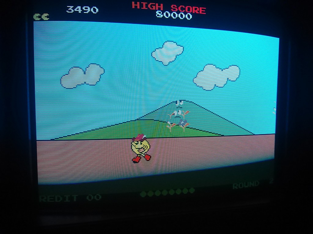
Tests programme, colour, video and sprite RAM 1 (note sprite RAM 2 is write-only)
Displays sprites dropping from screen to show sprite select and addressing is working (tries to show all 8 but most boards only have 6)
Shows real-time status of inputs and DIPs
I recently got two Operation Wolf boards from Muddymusic to fix.
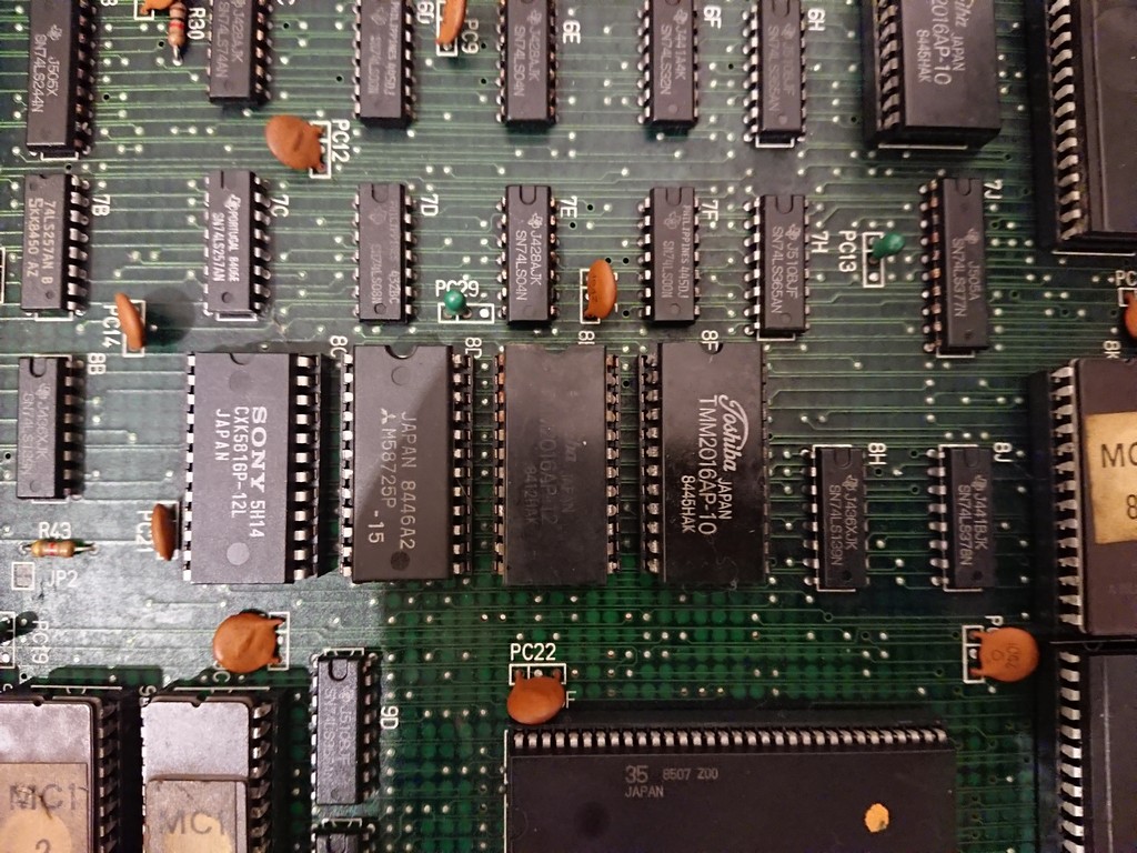
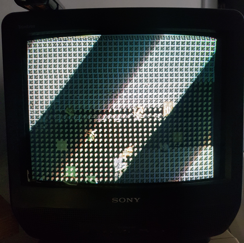
This board was not booting at all and I got a screen full of flickering garbage
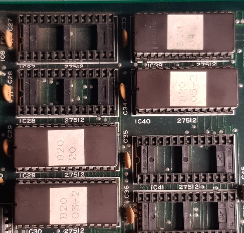
I removed all four of the 27C512 program EPROM’s and verified they were good. All of them matched the “World, Set 1” version in MAME.
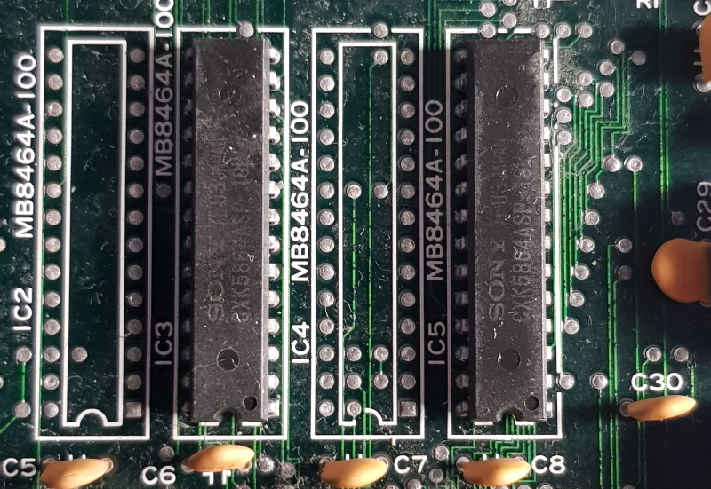
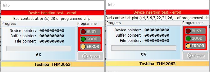
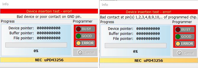
I confirmed continuity between all the address, data and control pins of both EPROM’s and RAM was present and correct and it was so I opted to remove the two TMM2063 work RAM chips and test those
As you can see both failed. I replaced them and tested but there was no change.
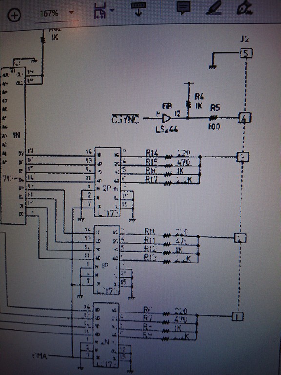
Next I started looking at the reset circuit.
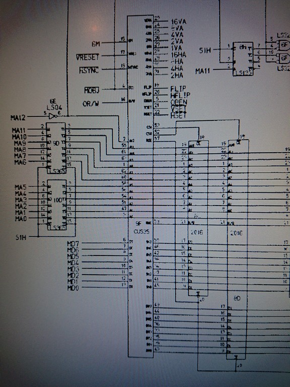
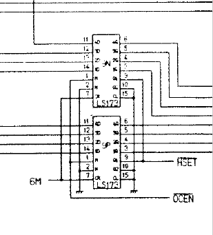
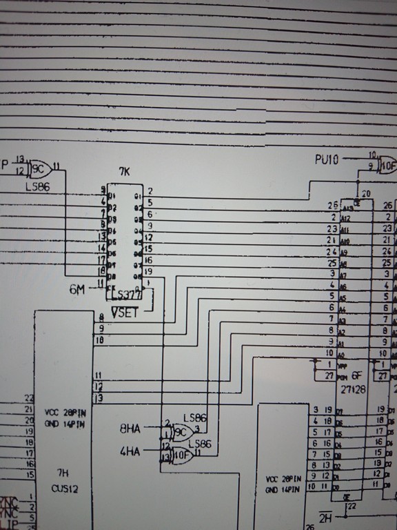
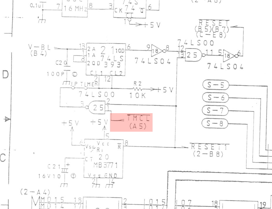
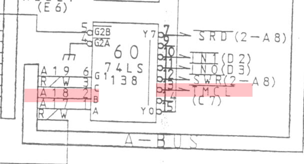
Here is the main reset circuit taken from the schematics
Using the logic probe I found that signal “/TMCL” (timer clear) was floating. Shifting focus to grid A5 on the schematics we see that this signal comes from pin 13 on the 74LS138 at location IC60.
Further probing found that the A18 signal on pin 2 was also dead. This signal is the buffered MA18 (address bus pin 18) and comes from the 74LS244 at location 65. Checking the signal on the LS244 revealed that it was present so there was a break in the trace some where.
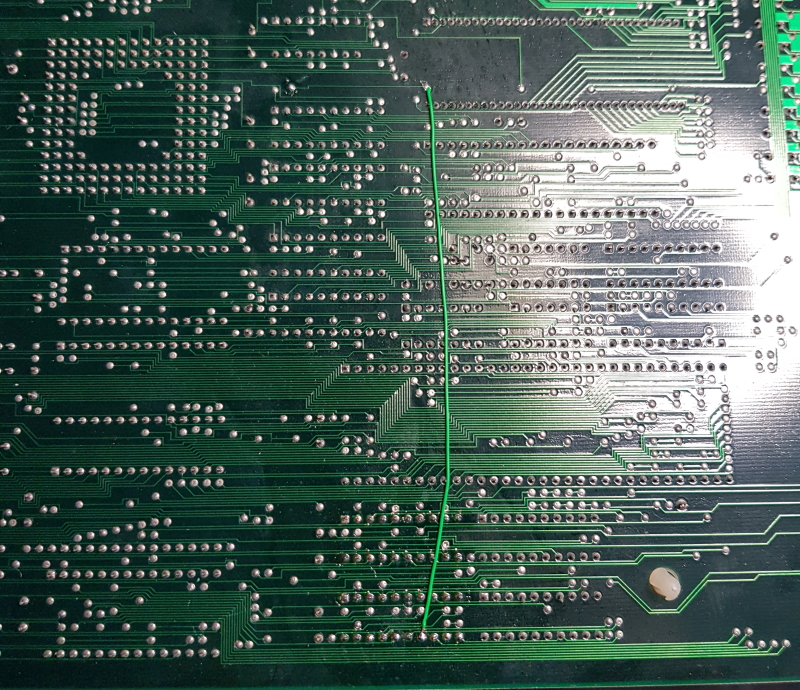
I couldn’t see anything obvious so I patched it with some Kynar wire
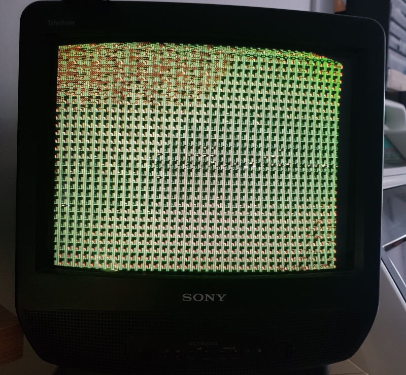
No on boot up I get no more resetting buyt the screen is full of garbage still
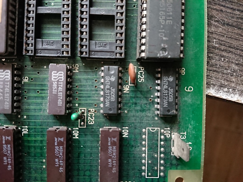
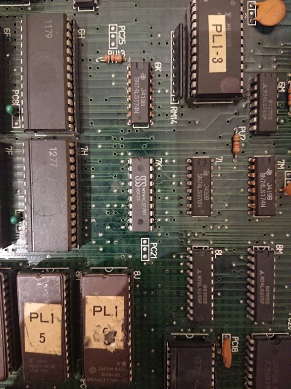
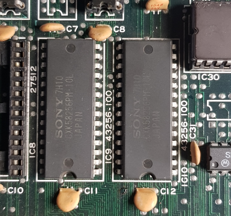
Next I started looking at the custom PC080 tilemap generators, more specifically the RAM connected to it
Checking both of these with the probe showed me there was no activity on most of these pins and some others were stuck high
I removed both of them and checked them, obviously both failed
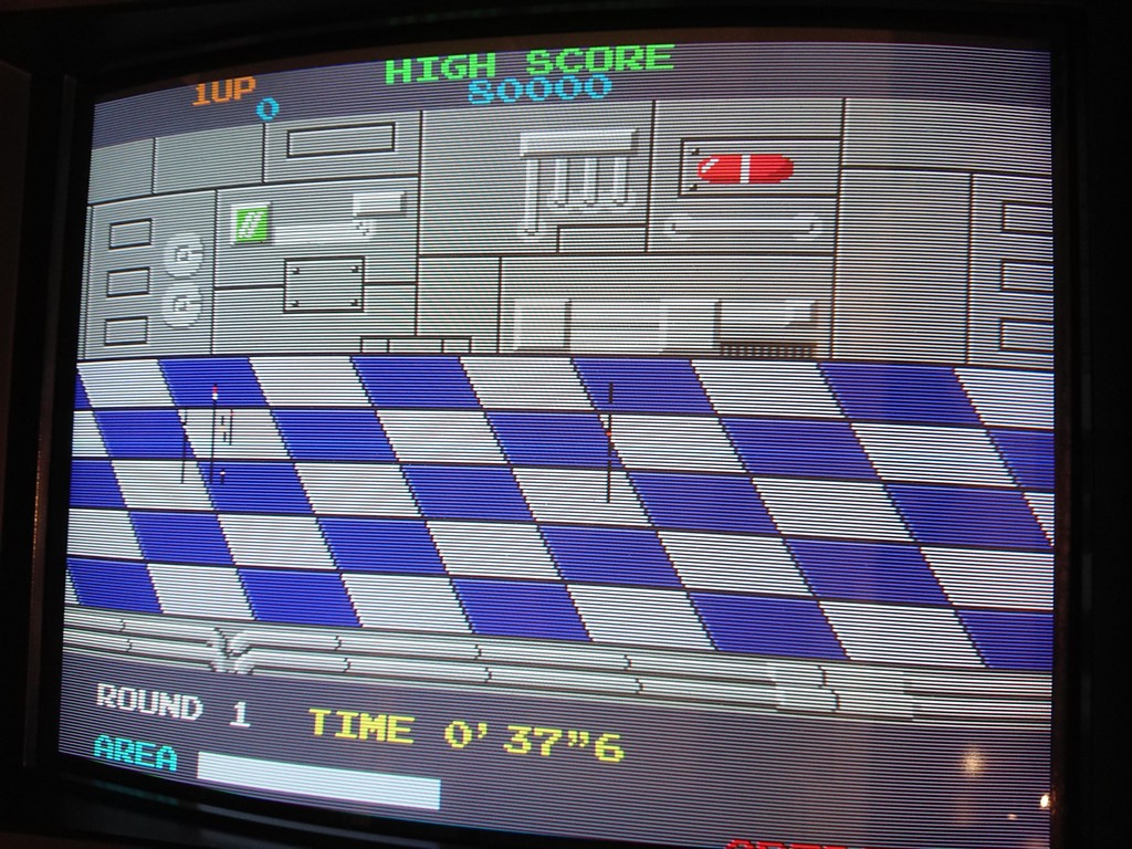
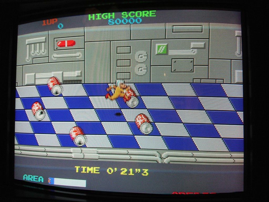
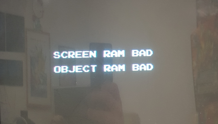
Replacing both of these now gives me something to see.
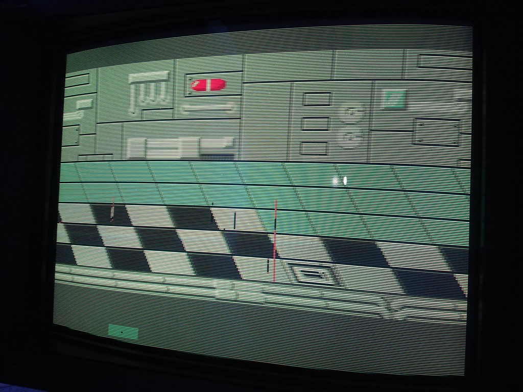
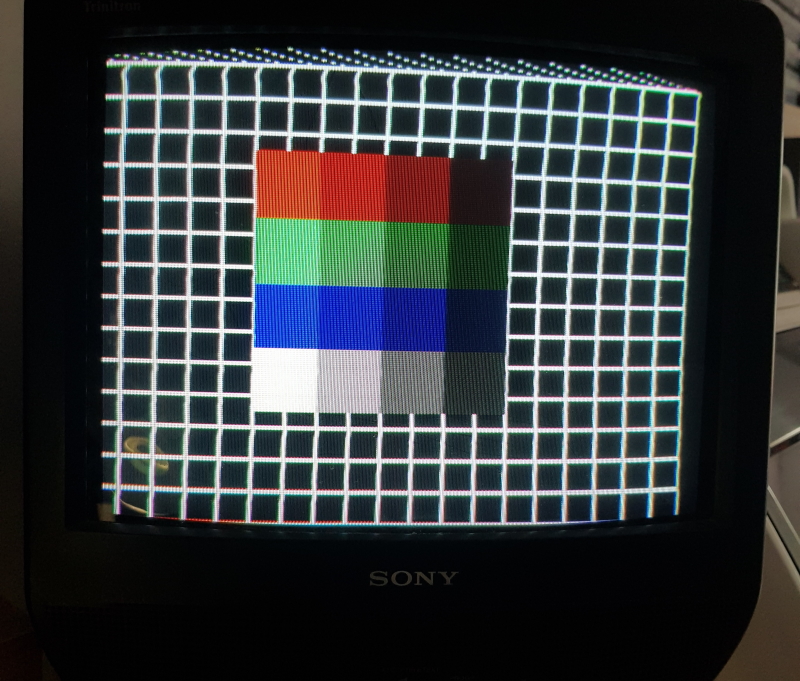
In test mode I get this
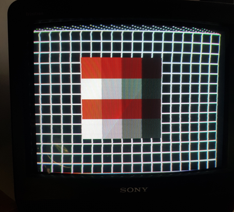
I looked into this fault for a good hour or so before I decided the RAM I fitted was too slow. Swapping for a faster RAM type fixed both of these issues.
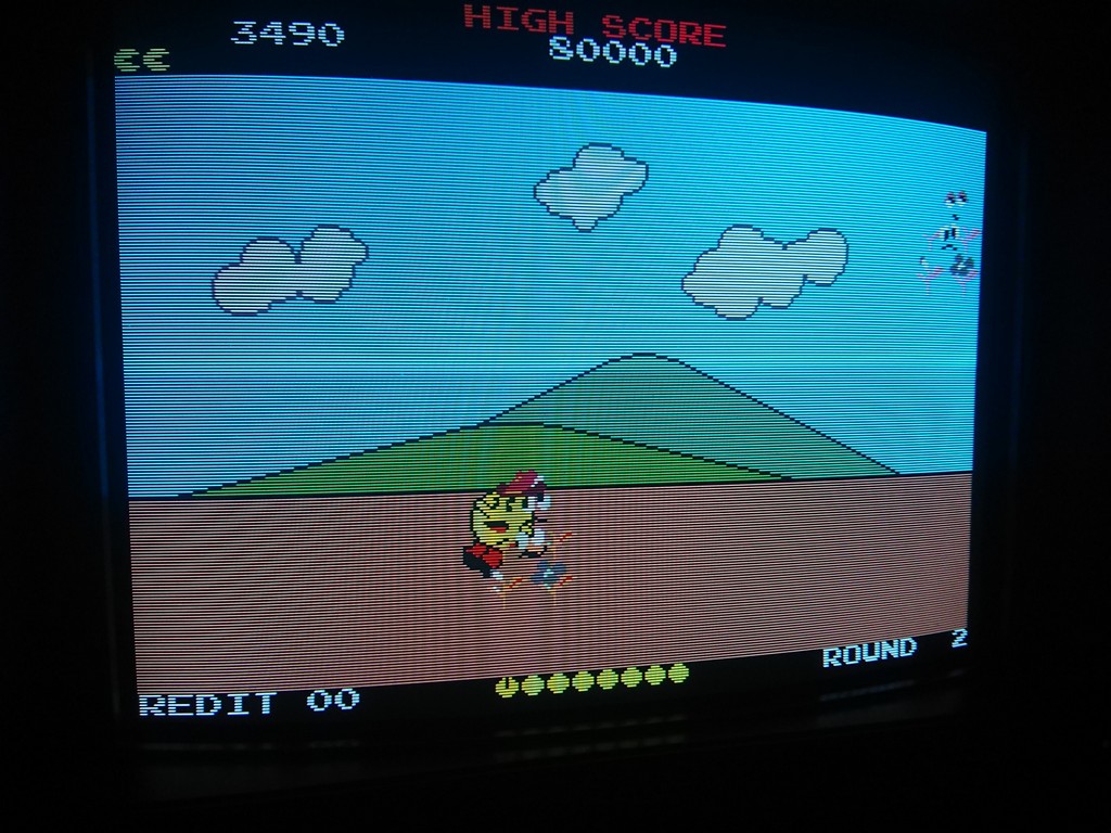
Now the board would successfully pass the self test in the test mode I could see that I had an issue with colours.
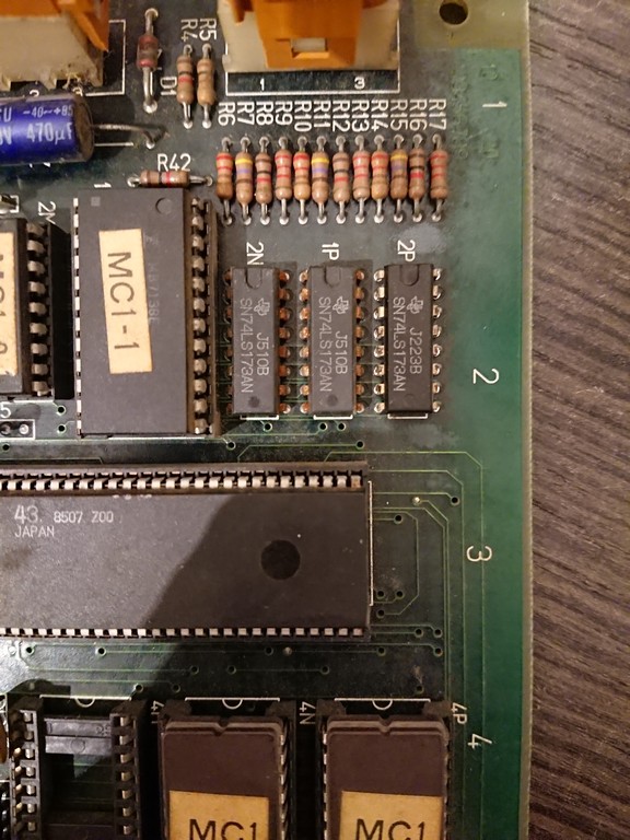
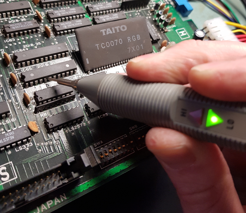
I started off probing the colour RAM at locations IC64 & IC65 and quickly found bit 4 of the address pins stuck low
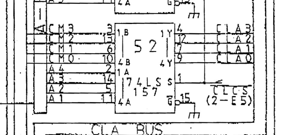
Using the schematics I could easily trace this back to a 74LS157 at IC52
Replacing this gave me my colours back
Now onto the sound board.
The good news is all the music was present and correct. The bad new was all the voice samples were not.
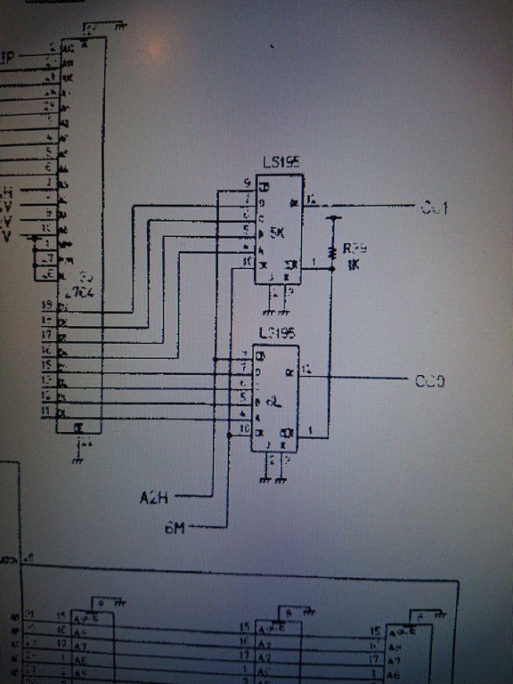
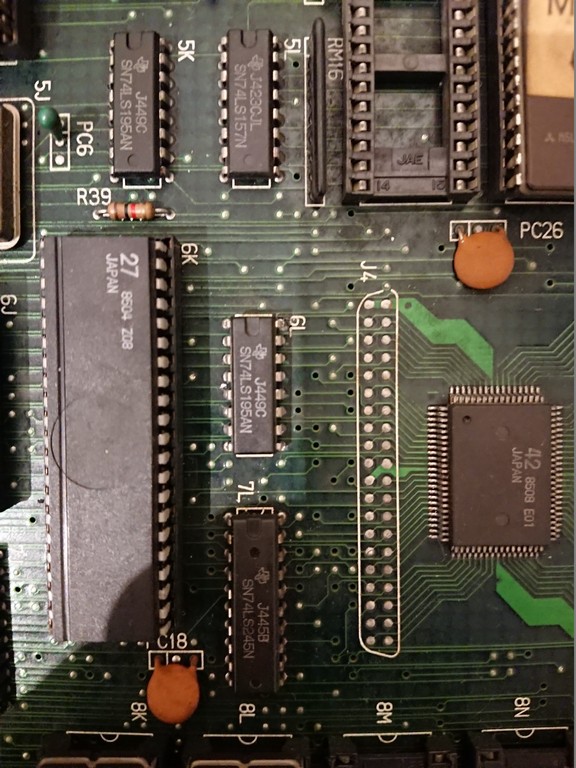
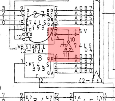
Again, using the schematics I see that ultimately the addressing for the Maskrom at IC21 gets set by a bunch of 4-bit counters at IC27-IC30.
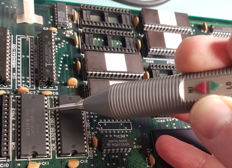
Probing these I found that the UP counter wasn’t pulsing at all
Checking the 74LS04 at IC32 revealed this inverter was bad so I replaced it and sound was restored but the sounds just carried on playing one after the other (never got a video of this).
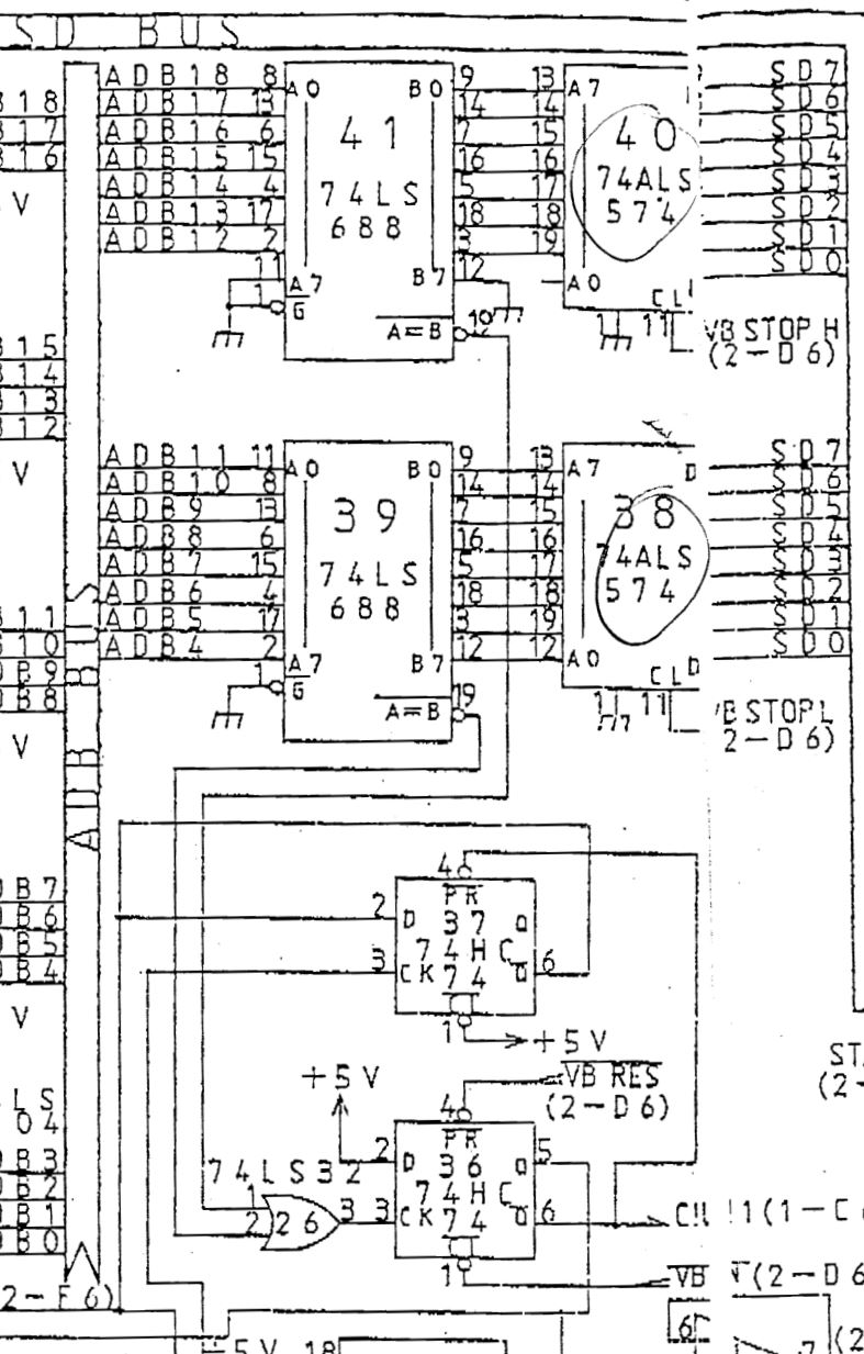
The Z80 sets the start and stop data by writing values to address $C002 & $C003 respectively which gets latched by a couple of 74ALS574’s and fed into the B side of a 74LS688 comparator
Using the MAME debugger I could see that the data being written to the 74LS574’s was correct but probing the /A=B output pin 19 of the comparators showed that these were either never matching or they weren’t working.
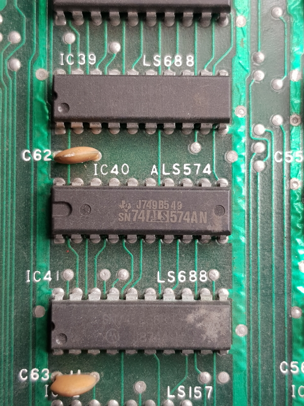
I couldnt find issues up stream of these so I desoldered them and replaced them with pulls from another board as I don’t have any spares.
I now have working sounds and fully working board set ready to return.