This is something I’ve wanted to do for a while but never got around to.
The following is a mix of my personal thoughts and findings. I realise others will have the same equipment and the operation of these will likely differ.
This post is in no way a “What to buy” guide. It is meant to show how three different probes work at different voltage levels.
I’ve got three logic probes but only ever use one of them as I really like it but is it giving me the most accurate reading?
Lets take a look
So here are what I’ve got.
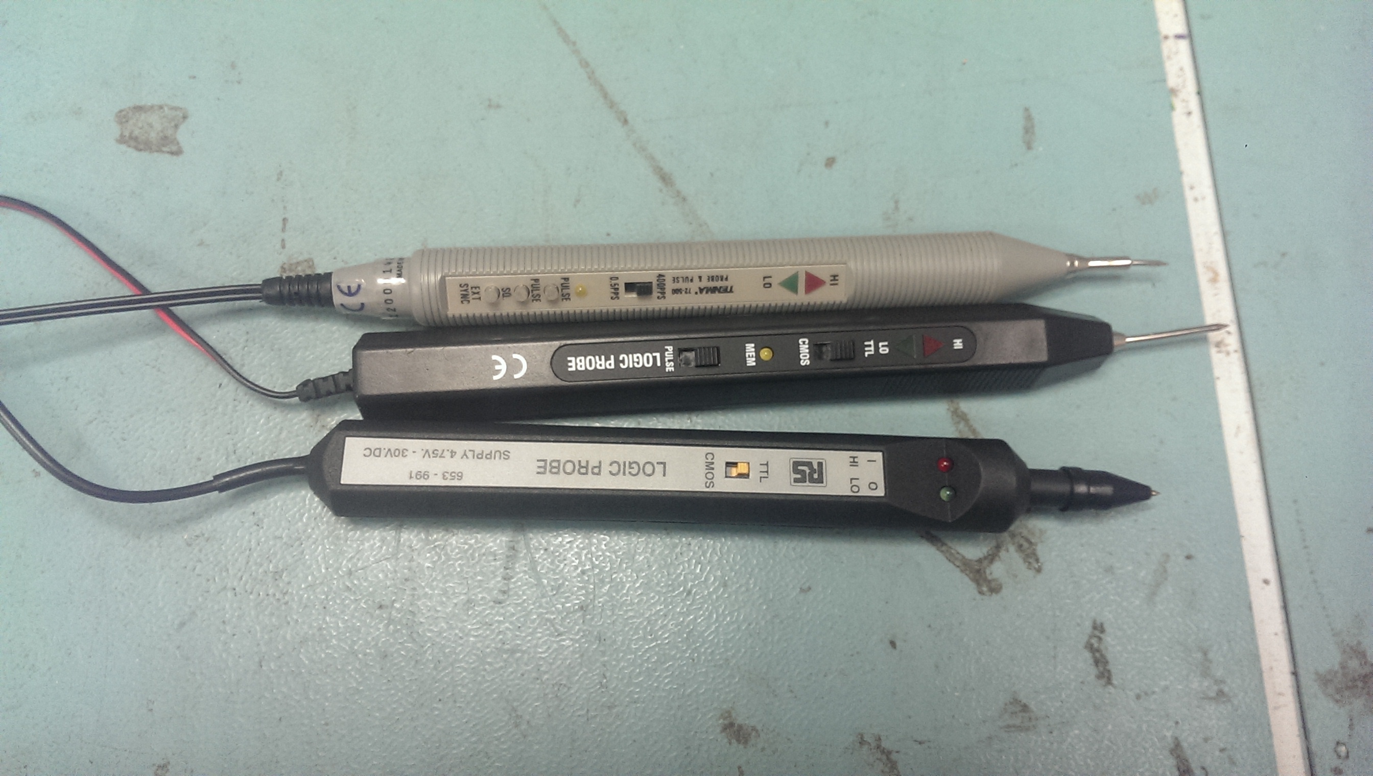
Top one is a Tenma branded one (also seen this under different brand names). This is my probe of choice.
Second one is an unbranded one. Used this once and it feels really cheap in hand but it does have a buzzer in it to accompany the LED’s which is nice.
Lastly is an RS branded one. This is a recent eBay purchase bought mainly for this write-up.
First off, lead length.
There is nothing worse than being restricted but short leads when probing around a board.
Tenma = 58cm
Unbranded = 146cm
RS = 171cm
So my probe of choice has the shortest lead length. I must admit it has hindered me in the past.
To test the logic thresholds I used my programmable PSU and used the outputs that have a common ground.
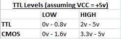
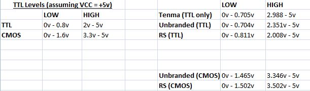
Here are the ‘official’ threshold levels according to Wikipedia for TTL and CMOS (assumming VCC = +5v).
The pictures below show the voltage at which the LOW LED goes OFF and the voltage at which the HIGH LED comes on.
Lets look at the Tenma probe to start with.
This probe only supports TTL logic levels where as the other two can switch between TTL and CMOS.
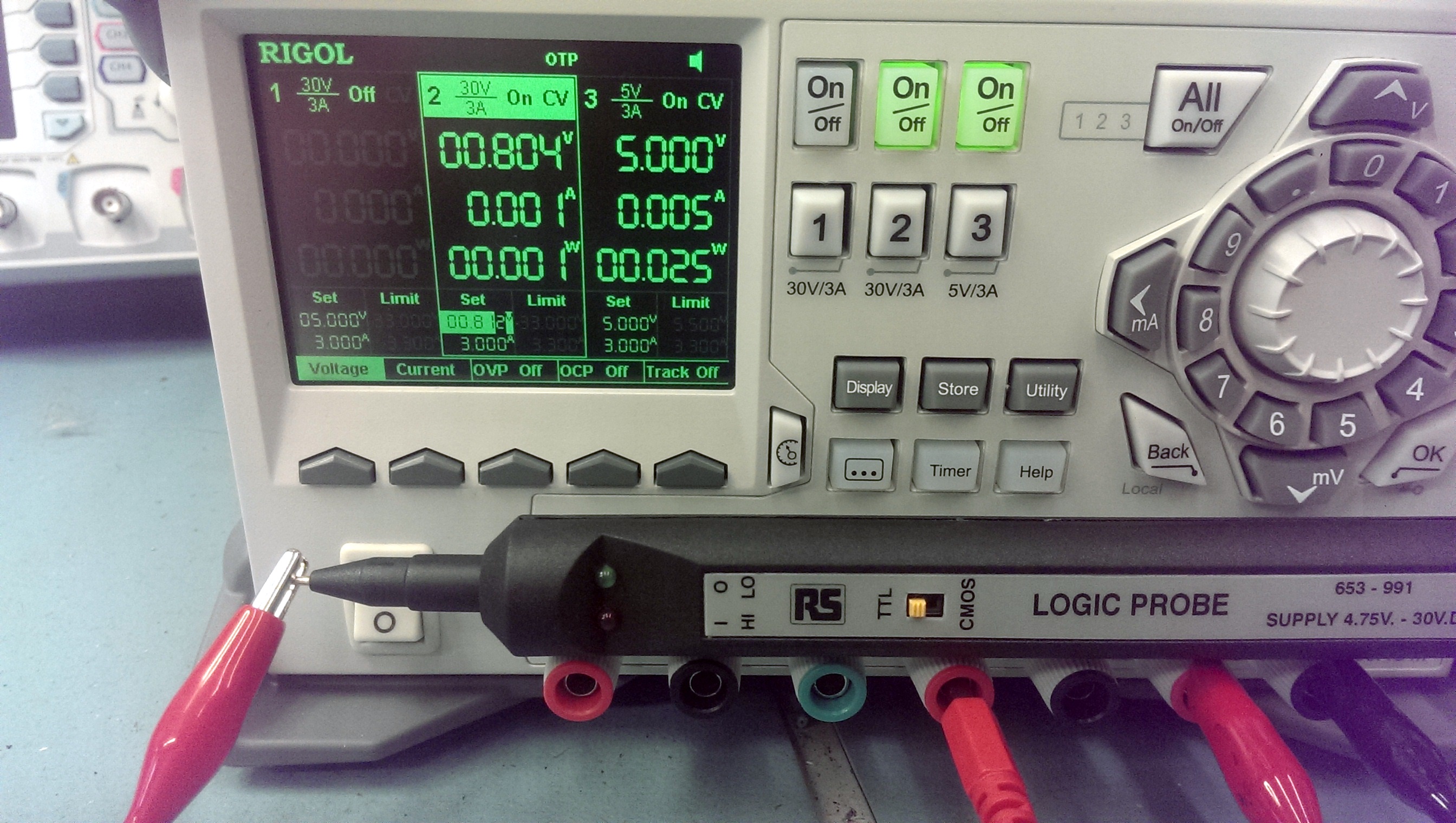
NOTE: You want to be looking at the smaller voltage settings at the bottom (under ‘Set’). This is the actual voltage settings and was checked for accuracy with a Fluke multimeter.
LOGIC LOW THRESHOLD (TTL)
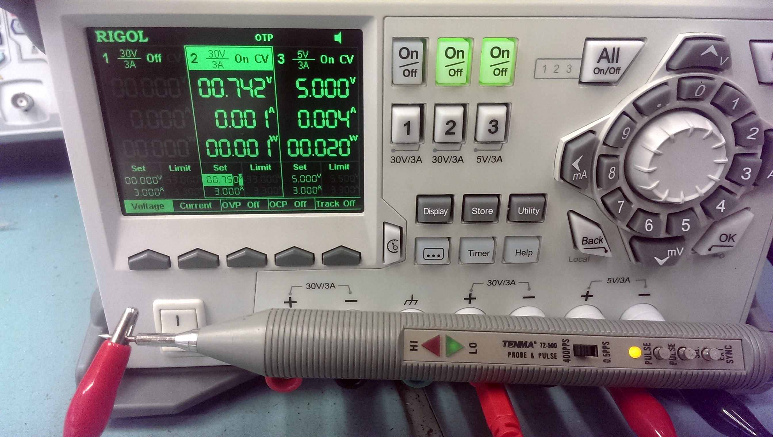
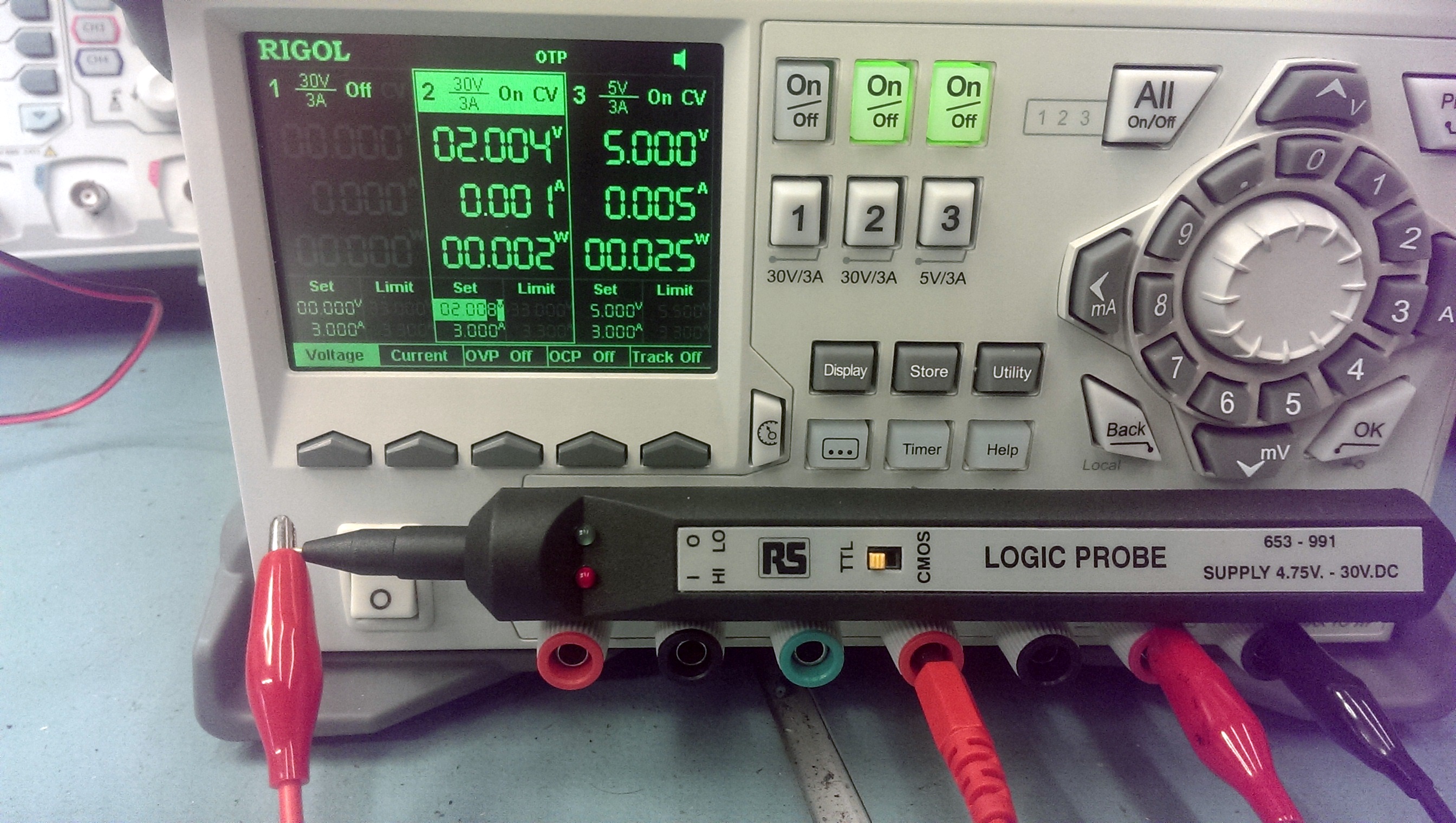
LOGIC HIGH THRESHOLD (TTL)
As you can see the LOW level begins to show around 0.1v below the stated thresholds. Not too bothered about that. Whats more worrying is the HIGH trigger point, its nearly 1v out of spec.
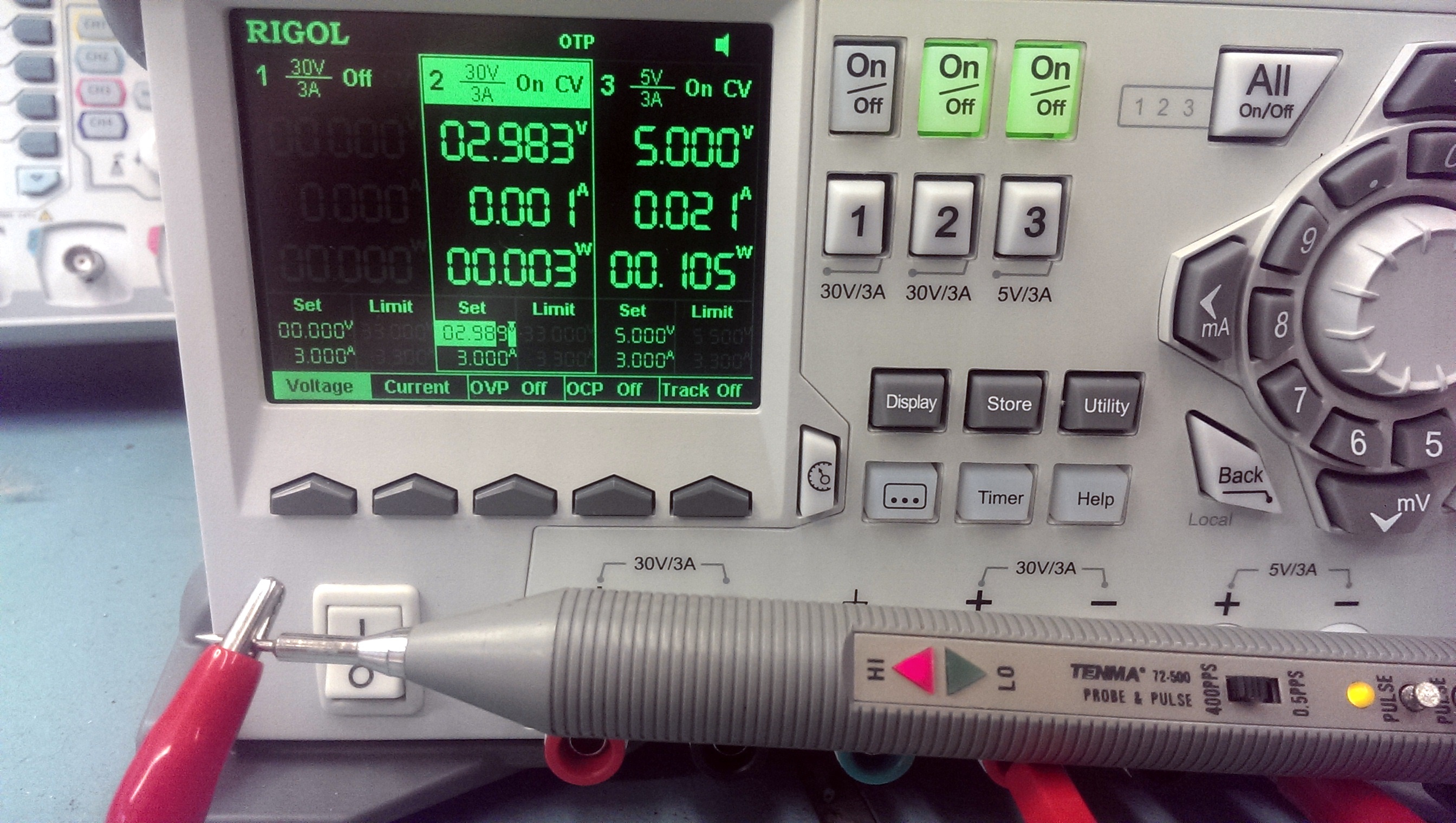
Next up is the unbranded probe
LOGIC LOW THRESHOLD (TTL)
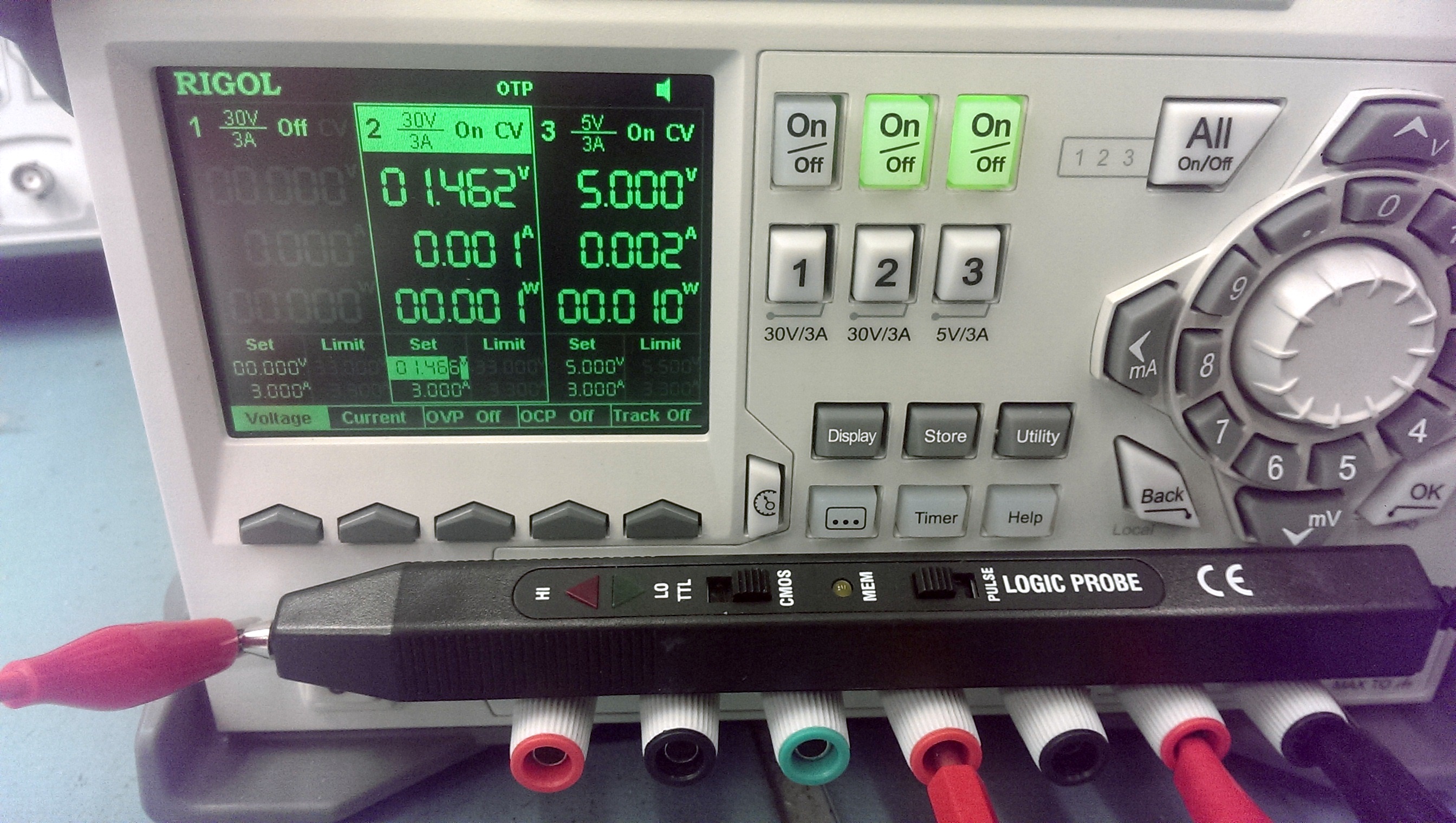
LOGIC HIGH THRESHOLD (TTL)
This has similar LOW trigger levels as the Tenma one and the HIGH trigger is around 0.7v lower bringing it nearer to the thresholds stated. Not too bad.
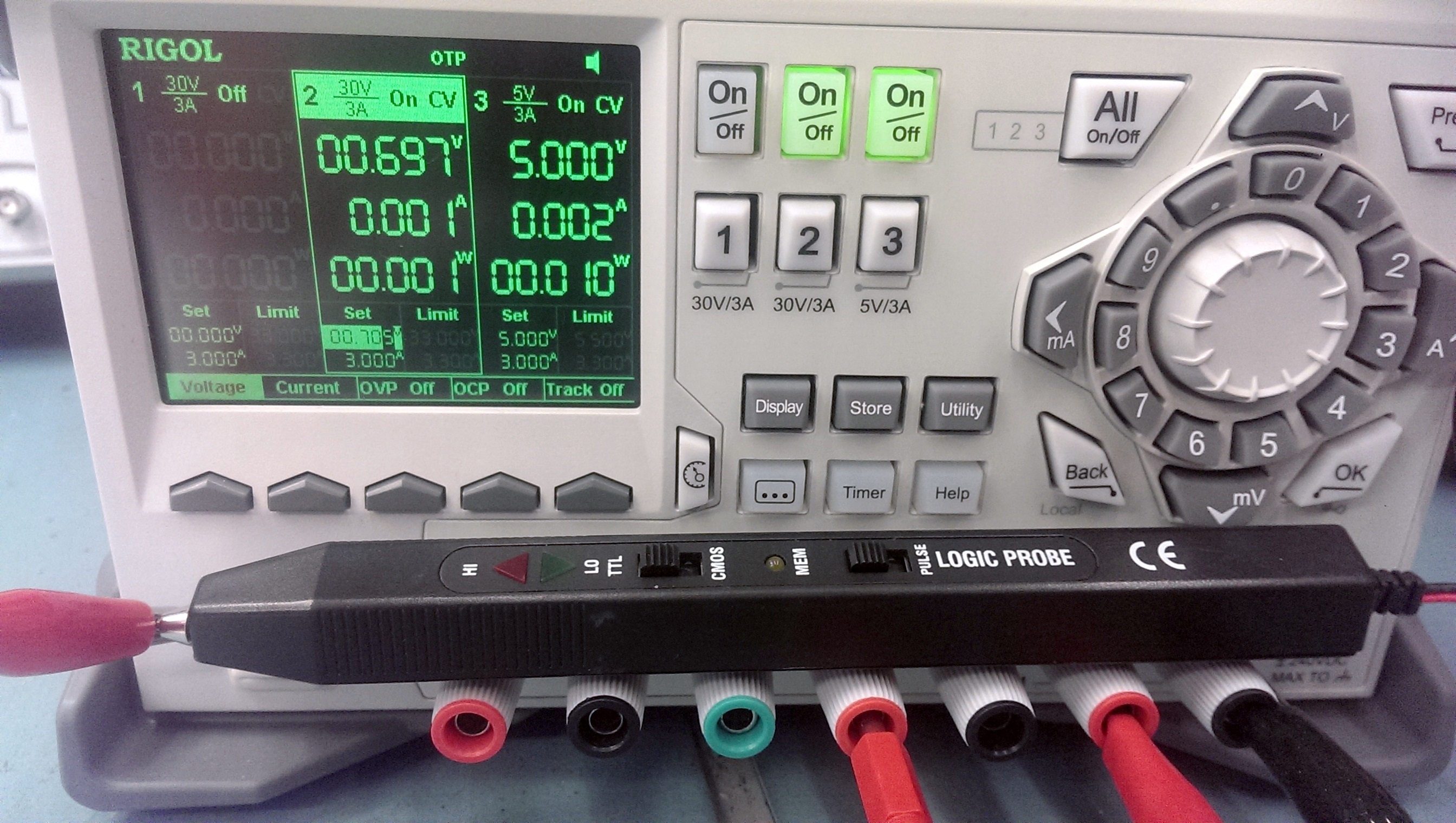
Finally the RS branded probe. The pictures are pretty useless here as the low brightness level of the probe at these voltages make it difficult to capture on camera but its there.
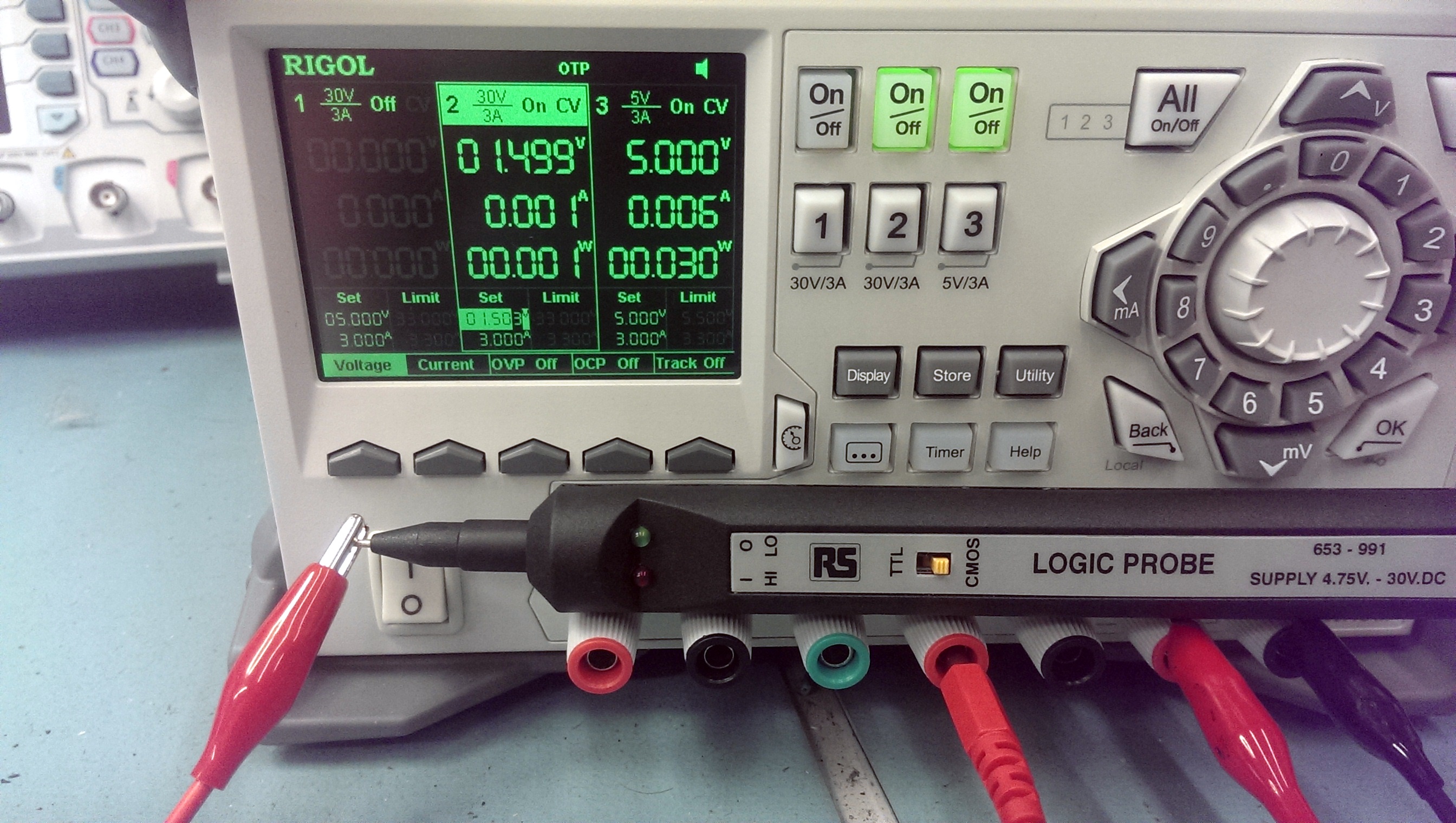
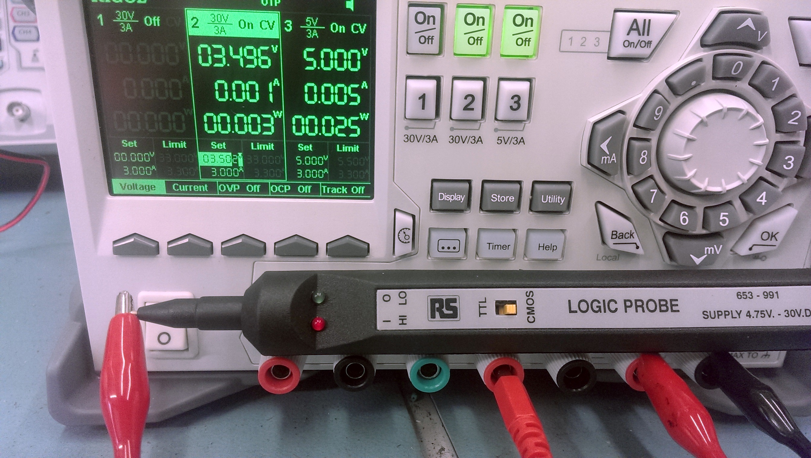
LOGIC LOW THRESHOLD (TTL)
LOGIC HIGH THRESHOLD (TTL)
Results are very positive for this probe on the TTL setting.
Next I test the CMOS setting. As the Tenma cannot support CMOS it is obviously excluded from this test.
Unbranded first.
LOGIC LOW THRESHOLD (CMOS)
LOGIC HIGH THRESHOLD (CMOS)
The LOW trigger is a bit low here but the HIGH is pretty good.
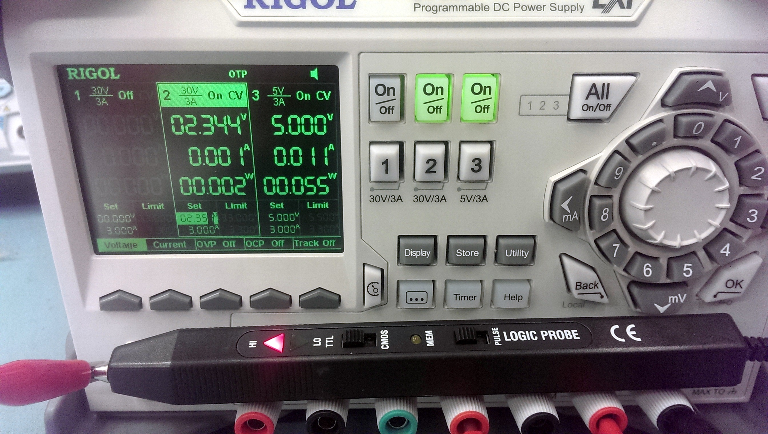
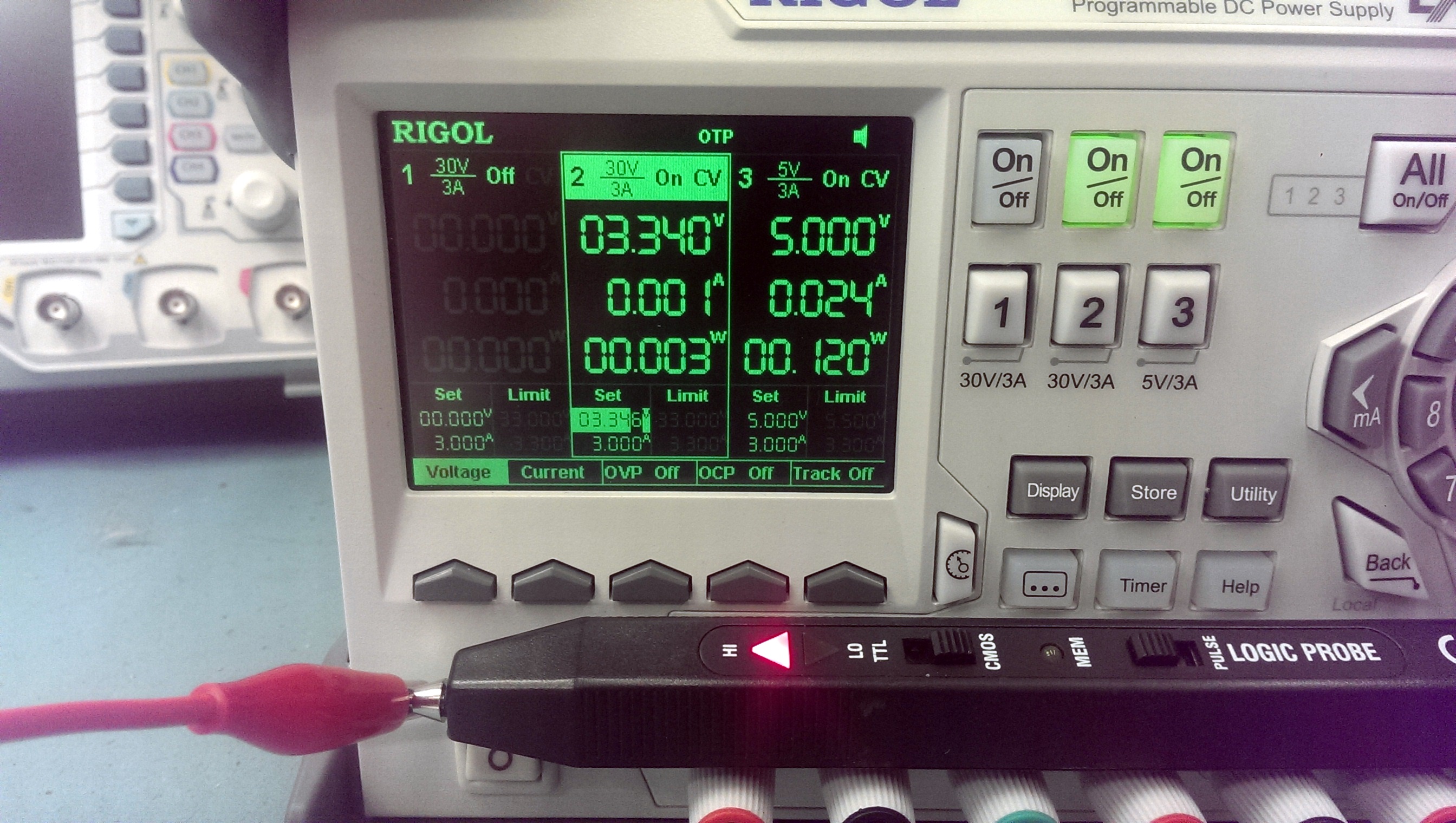
Now for the RS probe. Once again the pictures are pretty rubbish as the low level of the LED doesnt really show up on the camera but I assure you it is there.
LOGIC LOW THRESHOLD (CMOS)
LOGIC HIGH THRESHOLD (CMOS)
The LOW trigger is much the same but the HIGH is a little higher than the unbranded.
So here we have the full results
This test wasn’t the greatest and it is only my interpretation of it. For example, should I have taken readings when the LED’s were at full illumination? Different people will prefer different things.
The unbranded probe didn’t seem to have that dimming of the LED’s depending on the voltage. It was clearly either ON or OFF. Whether this is a good or bad thing will depend on user preference. For me its not too good. This probe however is the only one to have the buzzer which is a nice thing to have sometimes.
I think for me the RS probe will now be my probe of choice. It has nice long leads, feels good to hold and use and the results were decent too.