‘For Sale’ Section

 General  Comments Off on ‘For Sale’ Section
Sep 242017
 

As you may now notice there is a new tab on the menu bar called ‘For Sale’.
At present this is just a simple gallery showing items that we may be selling at any particular time.

If your interested in any items then please contact the seller directly via the contact form

 Posted by at 6:03 pm
Sep 112017
 

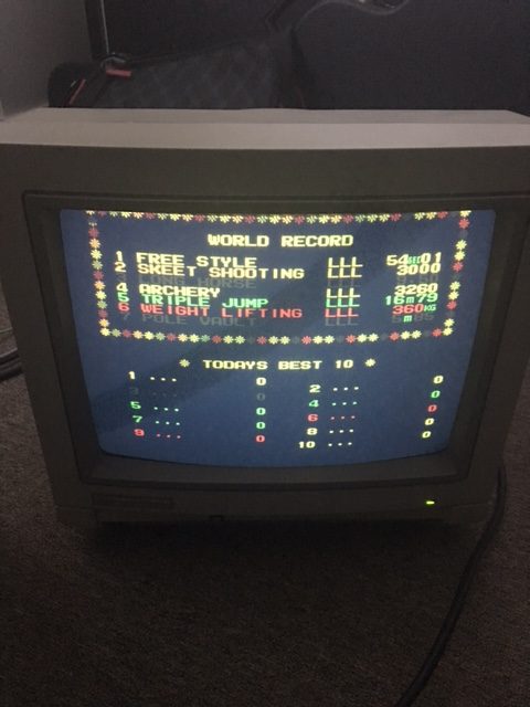
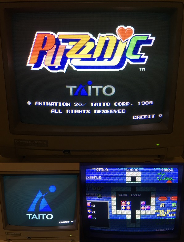
During my Hypersport’s repair I discovered a problem with the display of my Commodore 1084S monitor. Notice blue missing for “3 LONG HORSE” and “7 POLE VAULT”.

This will be the third time I’ve performed a repair on this old monitor which I’ve had since the early 90s for my Amiga 500 and 2000. At first I would suspect the AV7000 Supergun as the culprit. But subsequent tests would prove otherwise.

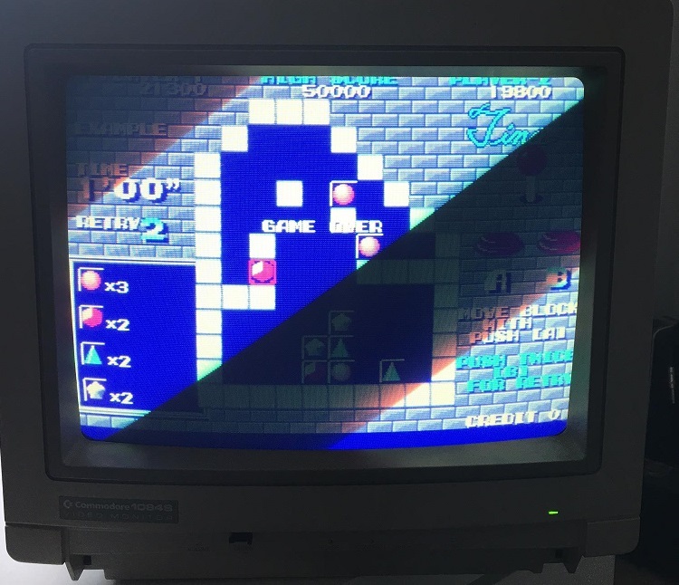
There’s definitely a better picture with composite or svideo from my c64 and Atari 8 bits but there seems to be a problem showing blue on the RGB input even though some blue is there ( turquoise , cyan.. etc ) in other images. Adjusting the blue gun and turning up the contrast just makes the backgrounds in Puzznic more blue. Where blue is supposed to be on the screen, it seems to not be present as though the signal were being cancelled out.  With no RGB signal to the monitor at all, it defaults to a blue screen instead of a white one.
Apologies for the sync bands.
I suspected the neck board transistors, so I pull out the one responsible for blue and tests with my multimeter show it’s fine. I even swap the transistors around to see if the problem would move to the other gun….  but it doesn’t.
I found this really good post on eab [ English Amiga Board ] by Loedown
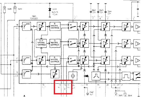
IC502 TDA 3505 pins 12, 13, 14 are RGB in from Euro Connector /SCART, check voltages there to begin with when inputting a perfectly white screen. Then follow the voltages through to transistors TS604 – 606.
The schematic shows the analogue inputs go directly from the RGB connector to the Philips TDA3505 IC via some 100nf caps. Pins 12,13 & 14 are the input RGB signals. I measured 4.3v for red and green but 9.1v for blue. That seems a little too high for blue and the schematic indicates 4v for those signals.
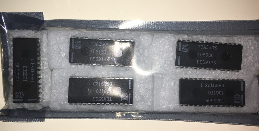
I order some TDA3505s on eBay from atarifreakz and my package arrives a few weeks later.
 
Not wasting any time. I replace the chip and the picture is now perfect!
The Taito logo and blue shadow around the Puzznic logo is now visible. Notice the bricks and backgrounds are also showing up right compared with the previous screenshot.
 
I wonder if there will be a part 4 🙂

ROMCMP Frontend

 General  Comments Off on ROMCMP Frontend
Aug 272017
 

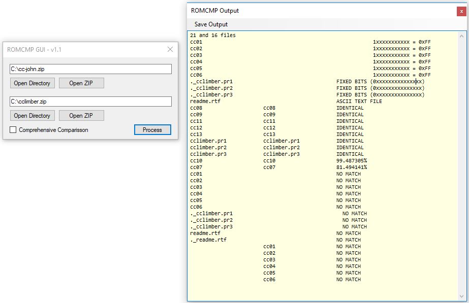
In an attempt to help more people start using MAME’s fantastic ROMCMP utility I have made a simple GUI frontend for it.

Program can be found in the Downloads section under “PC Software”

 Posted by at 10:47 am
Jul 272017
 

Recently I’ve been working on some Windows based software to use the Data I/O 29 series programmers.
Its coming along well and I have a few people willing to test things out for me which has been great as its a pretty tedious task of trying things out and reporting back, rinse and repeat.
I captured a small video showing some progress.

The programmer itself isn’t all that hard to interface with as most of it is just issuing commands which are all outlined in the manual but there are a couple of things to deal with when it comes to uploading a file to the programmer.
I’ve also been collecting ID codes for programmers and modules so I can auto detect programmer and more importantly the module that is fitted. This allows me to auto populate a device list.
Ive tested this using a cheap USB to serial adapter and its been working fine.

 Posted by at 9:08 pm
Jul 012017
 

These system boards from Namco has a common problem: SMD capacitors

These caps expecially the ones produced in the 90s are very unreliable and sooner or later will start to leak

On my boards there isn’t one that has the ESR in a good range.

On Namco system NA ( Emeraldia, Tinkle Pit, Super World Court) or NB ( Point Blank, Nebulas Ray), the problems you will face are sound related ( low sound or scratchy ), on ND system ( Namco Classic Collections), the SMD caps are used also for the RGB amplifier and in addition you will get colour problems.

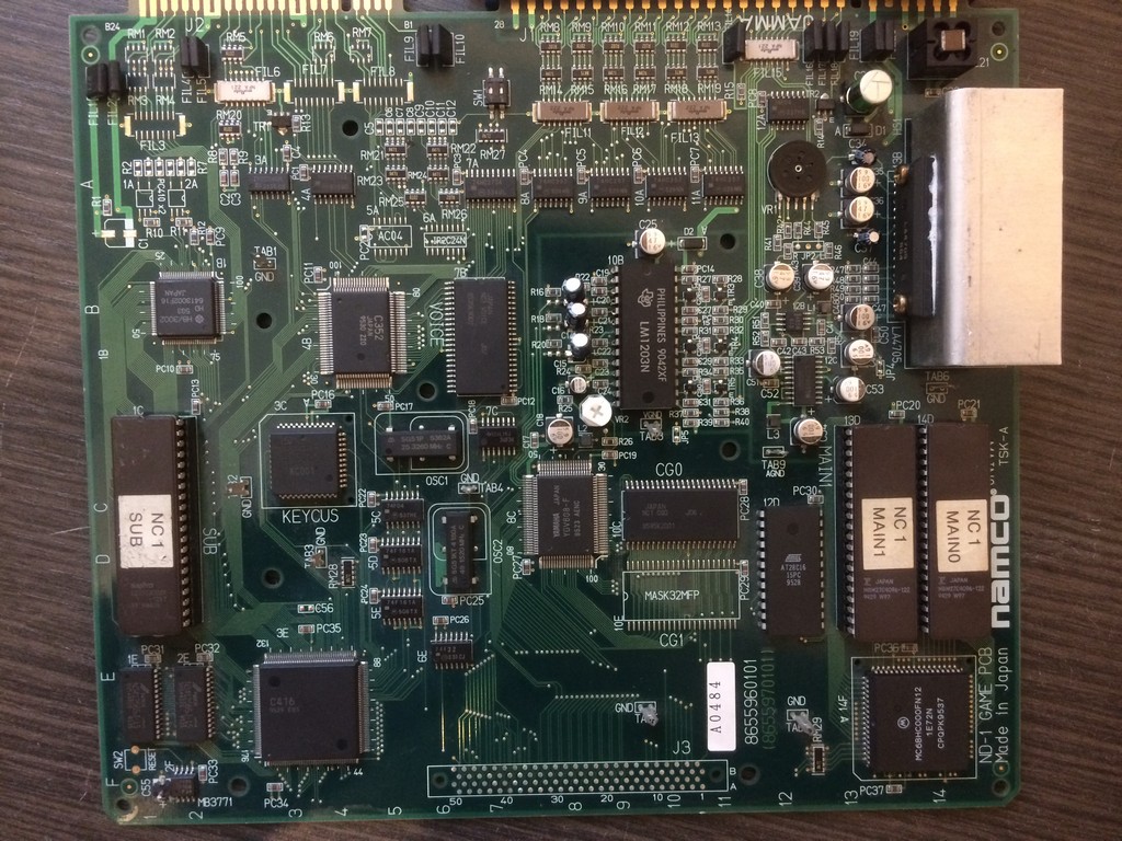
I will take as an example a Namco Classic Collection I just finished to repair and which had all the problems coming in about one week of intensive use after a while in storage.


First of all it started to have trails on the RED component of the image.

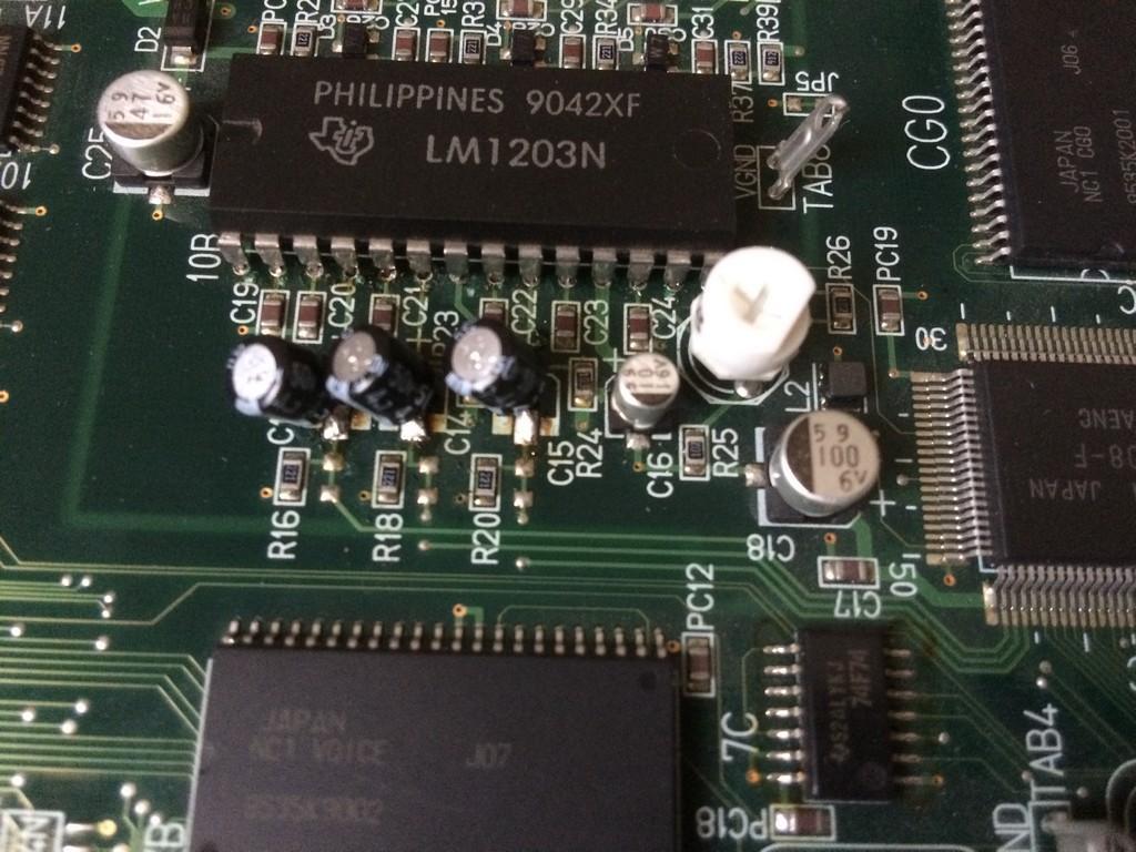
The system uses a common RGB amplier LM1203 which for example is used on the majority monitors neckboards

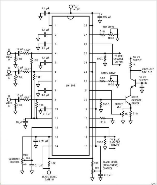
Here are the usual circuit taken from the schematics of the LM1203:

As you can see , on the inputs of each colour component you have to place a 10uF cap.

Namco engineers decided to use a 4,7uF but I tested and there are no differences between the two values.

So, if you have colour quality problems on your Namco Classics Collection pcbs, first thing is to recap the RGB input section using commercial

electrolitic caps.


I am not a fan of brute force recap, so with my ESR meter I usually check all the caps and change only the ones that have a very out of range value.

As said before, after few days I get no sound for a while and after about 5 minutes, you could hear it coming up but very scratchy.

The amplifier got also really hot after a short time.

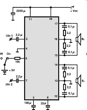
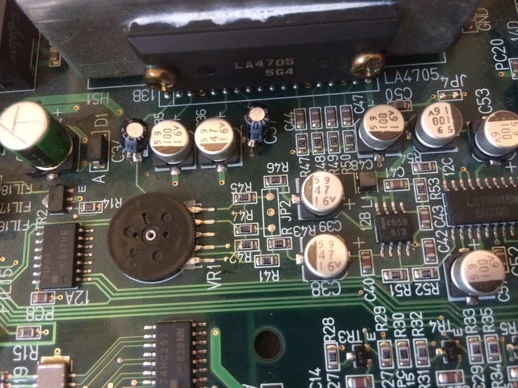
The system uses a LA4705 sound amplifier


I probed with the ESR meter all the caps and found out the both the small ones 2,2uF placed on  IN1 and IN2 had a value of more than 99 ohms.

The other ones also were really not in the specification range but to get sound back it was enough to change the small ones.


As said the sound section of Namco system NA and NB is the same more or less, therefore if you start to have low sound and you don’t have an ESR meter,

change the 2,2uF, 47uF (33uF on the amp schematics) and 100uF one.