Got the second board fixed up today.
This one had a lot more wrong with it and all caused by a previous repair attempt.
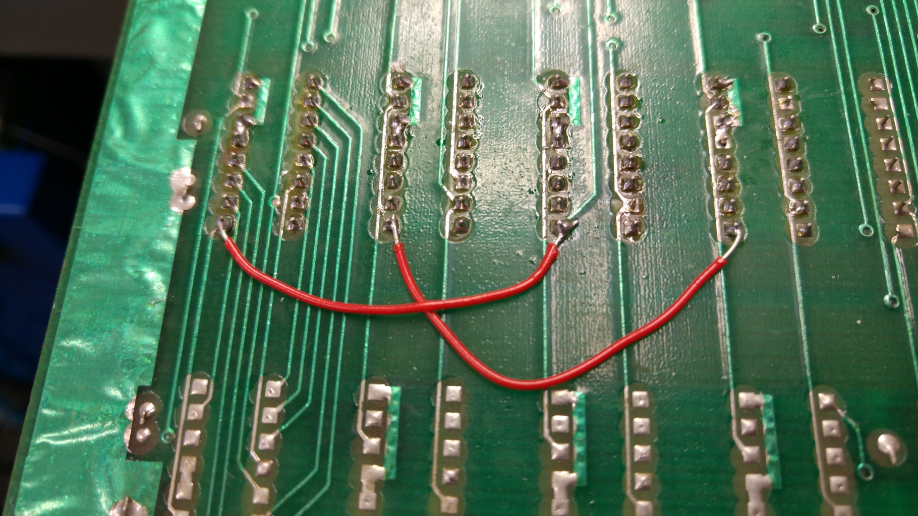
Visual inspection immediately revealed this.

I confirmed these wires were going where they should be and neatened them up a bit.
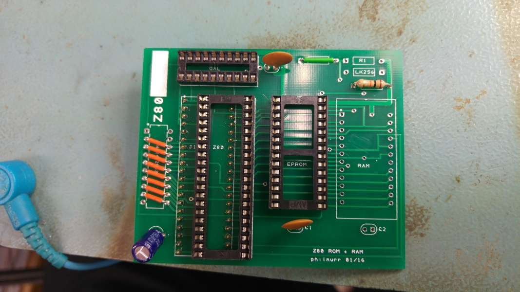
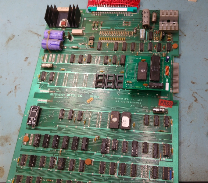
As with the first board all I got was a blank screen with the board not playing blind. At this point I had my smaller custom replacements verified so could do away with stacking the TTL riser and could just plug the Fluke straight in.
ROM checks were all good but the RAM checks failed straight away.
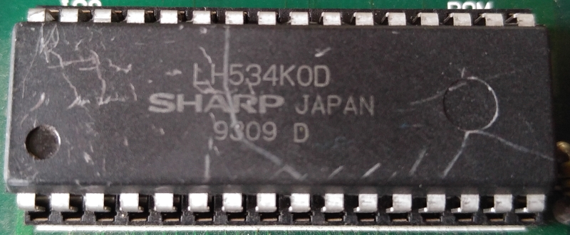
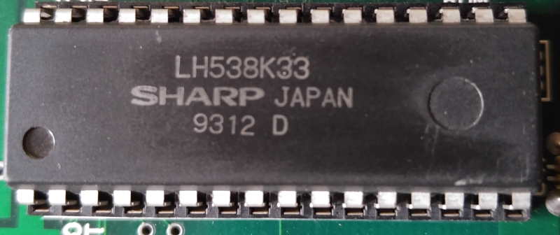
With the previous repair still fresh in my mind I knew where to look. the 74LS245 at 4H. This had a turned pin socket fitted and a 74HC245 chip inserted. The HC variation means its CMOS logic levels and typically aren’t an ideal replacement for LS parts. If you are going to swap them out you can use the HCT variety which are TTL compatible.
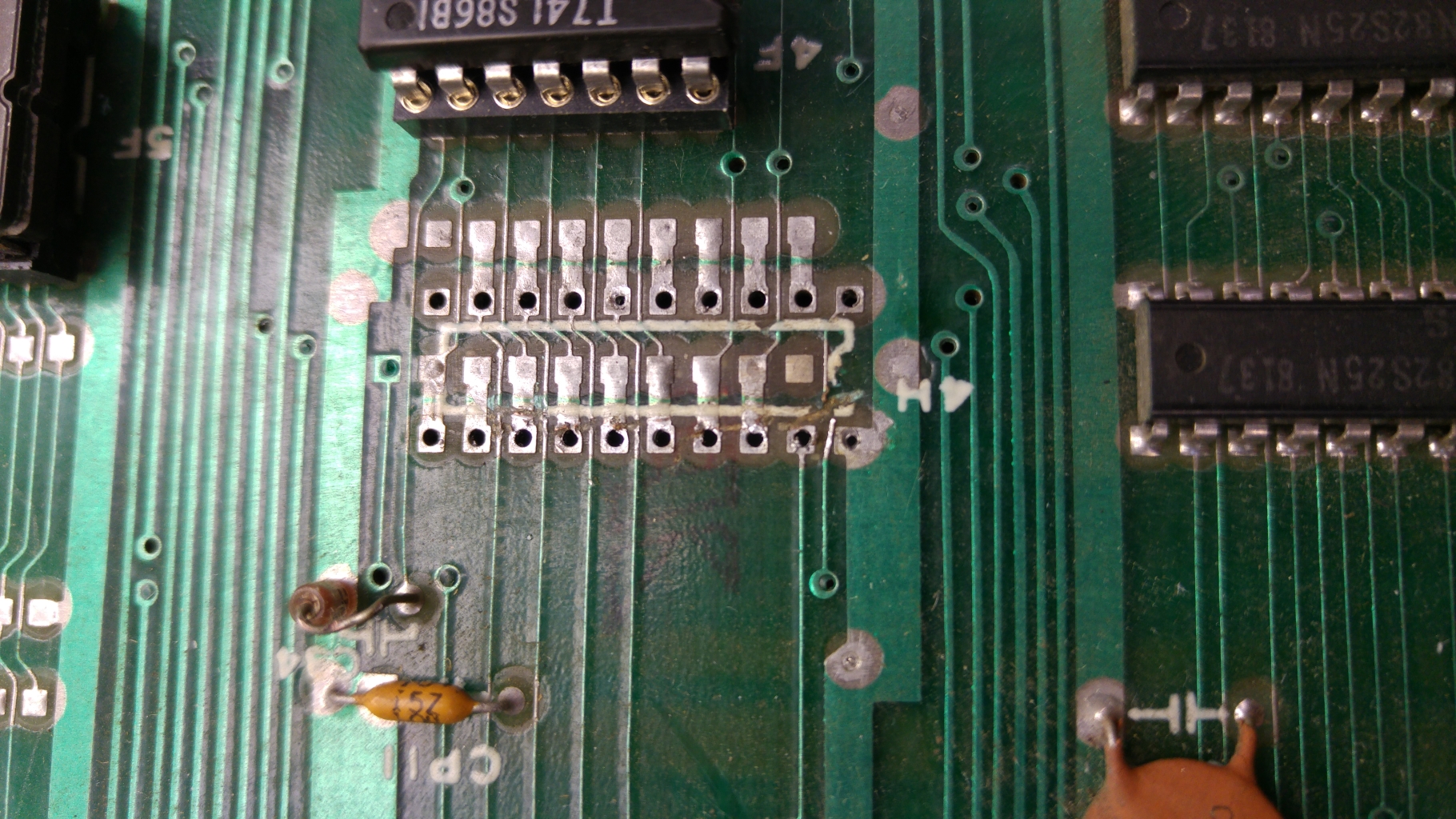
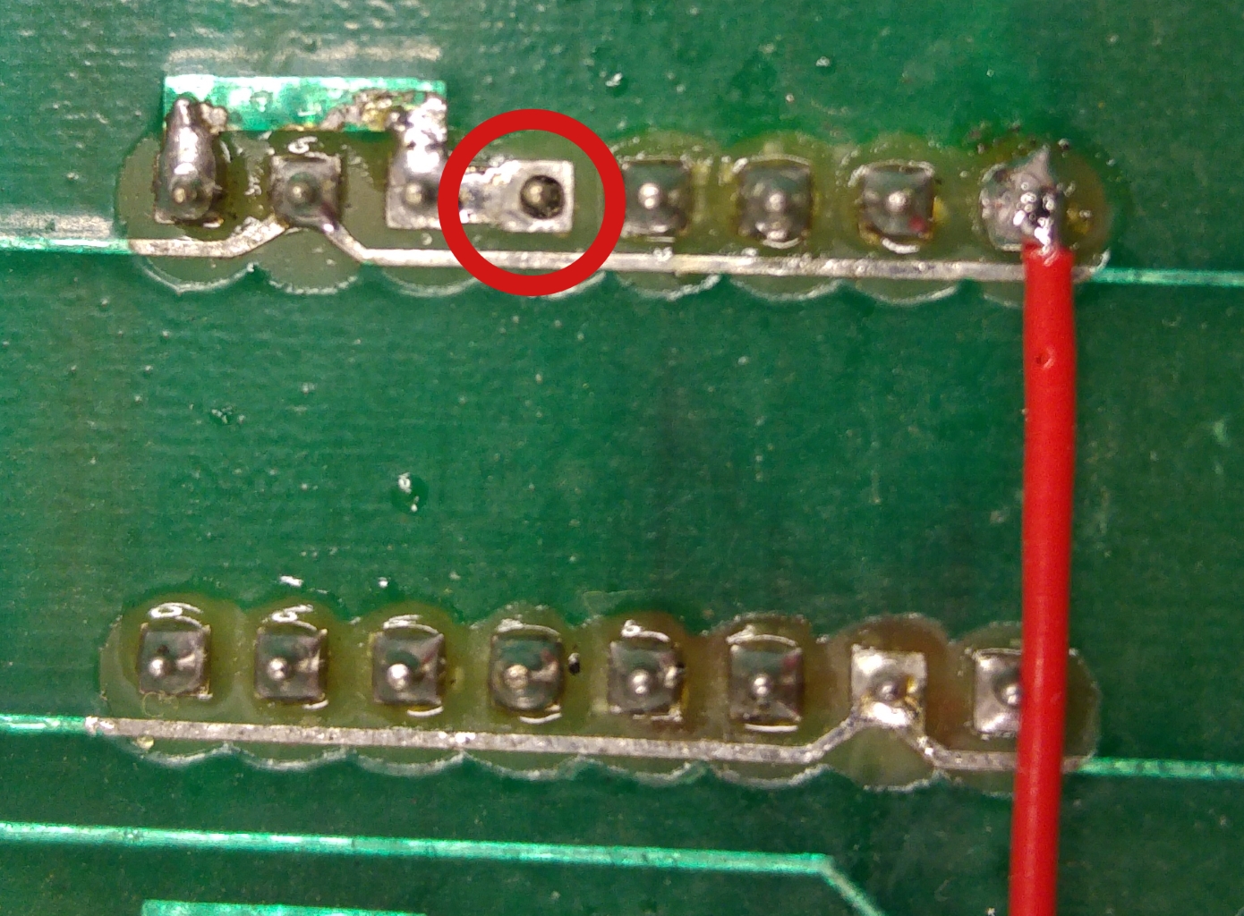
I replace this chip with a 74LS245 but it did not fix my issue. Checking the outputs of the 245 to the RAM led me to suspect a poor desoldering job of the previous chip as several pins weren’t connected to the RAM. I desoldered the socket and found this mess.

You can clearly see a the traces that have been ripped through. I patched these, fitted a new socket and continued my checks.
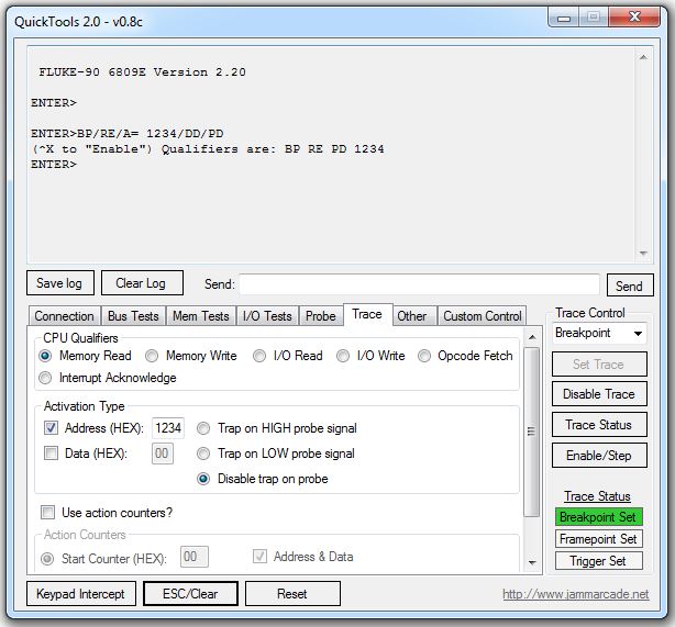
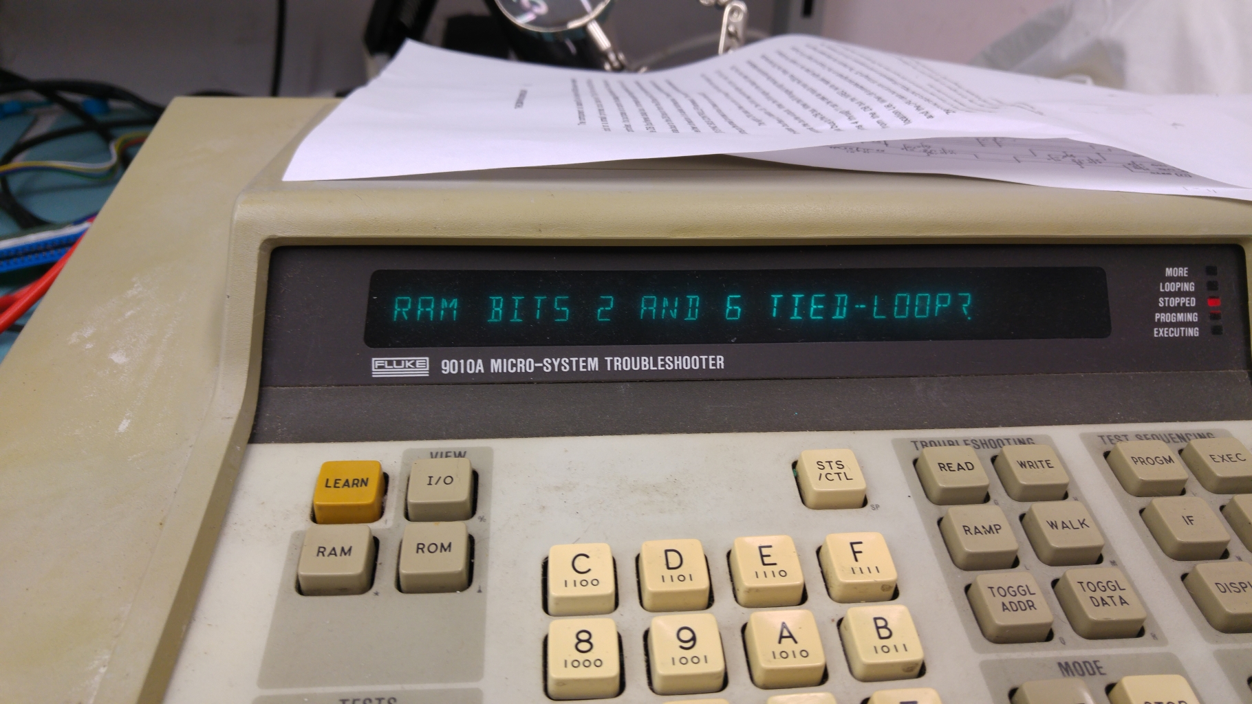
The Fluke now reported this.

Knowing the chip was good and the connections to the RAM were good I focused my attention on the CPU side of this chip.
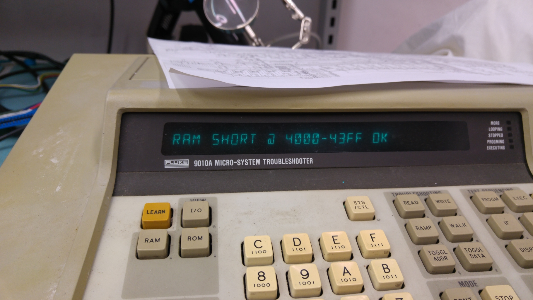
I knew my custom chips were good and I could correctly read the ROM’s so new the CPU socket was good. This didn’t leave me with many places left to look. I could almost certainly rule out some places as data bits 2 and 6 were across two different chips and the chances of both of the chips shorting together was a bit low. This left me with an 74LS273 at 4D and also to the dreaded crusty flux issue. Cleaning the flux cleared my short.

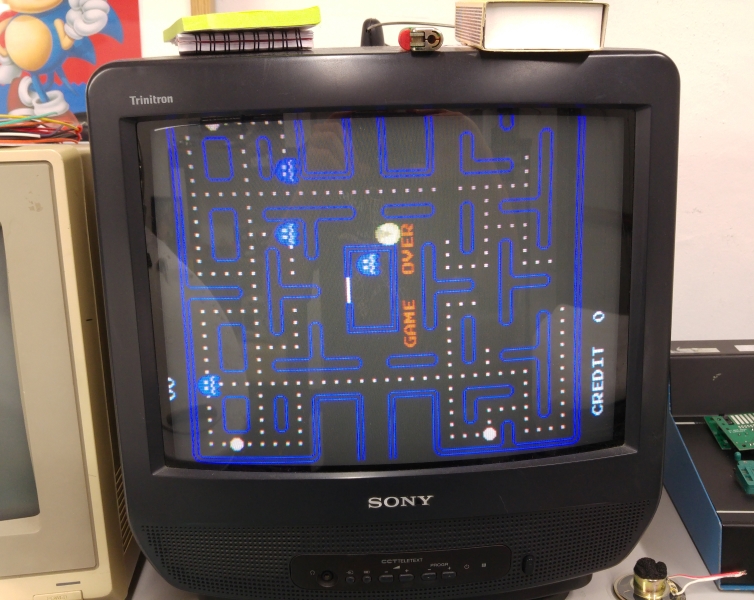
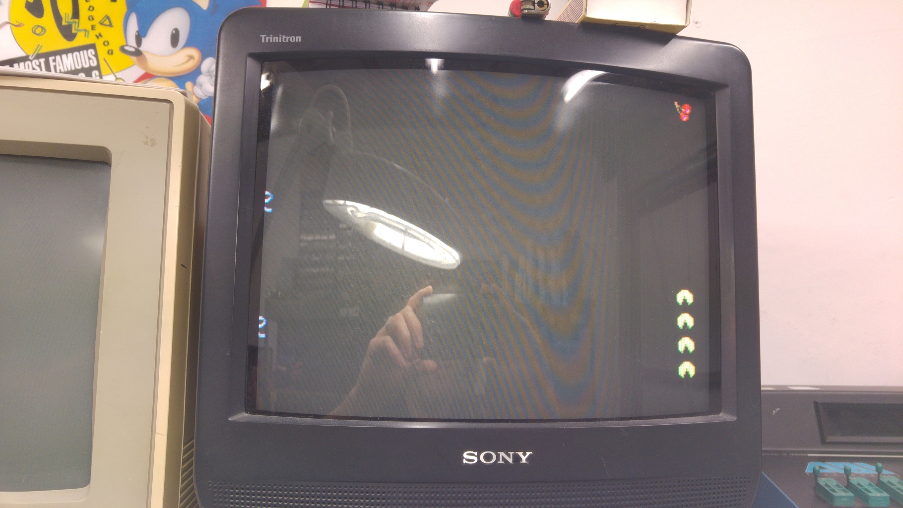
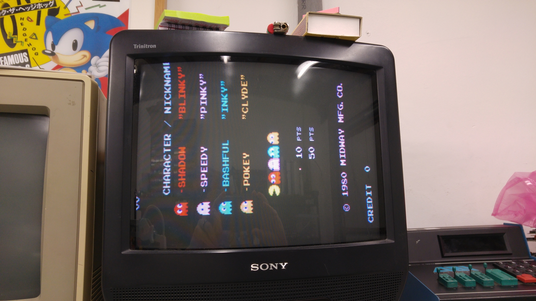
Now the game would boot but I get this

Only the score and credits were showing. If I started a game the lives were also showing at the bottom.
My attention immediately went to the 4 x 1bit RAM chips at 2A-2D and found there wasn’t a great deal of activity and some missing signals.
My heart sank right away as I could see turned pin sockets had also been fitted for all of these which most likely meant the same person had replaced them.
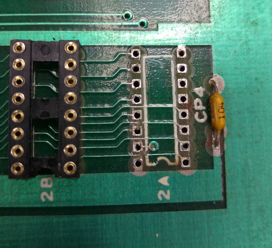
Sure enough there were several traces cut. I did remove one of the sockets just to see what I was up against.

Some severed traces here and doing a continuity test revealed more and more. I also found one pin not soldered.

A bit of time later after patching and verifying my work I fired it up and was all ready to feel pleased with myself on a job well done but the same fault was still present.
Confident the fault was still in the area I was already working I set back to work checking continuity and found the ‘Data In’ pin (pin 15) of a RAM at 2A was shorted to pin 1 of the RAM at 2B. Looking back at the picture I had taken I noticed a bit of stray solder bridging the trace that ran adjacent to pin 15 that I had missed earlier. I managed to remove it with a pin and a bit of patience.
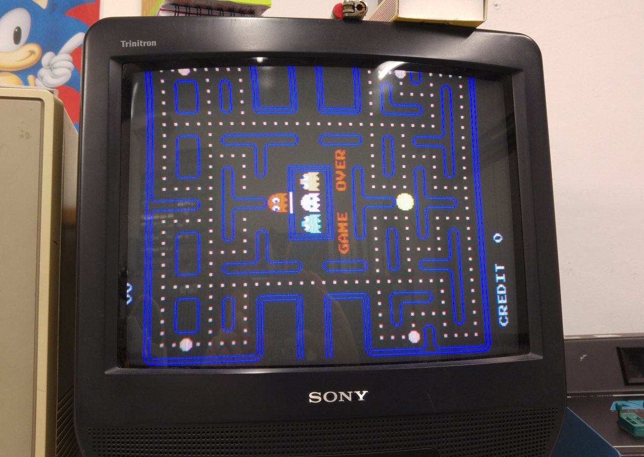
After that the board fired right up and plays fine.


