Corrado Tomaselli

No background in electronics. Learned everything by reading pdf books and expecially Video game logic Vol 1 by Atari and in general early Atari and Williams arcade manuals

Sunset Riders repair log #4

 PCB Repair Logs, Repair Logs  Comments Off on Sunset Riders repair log #4
Jun 182016
 

I got this pcb for a repair.

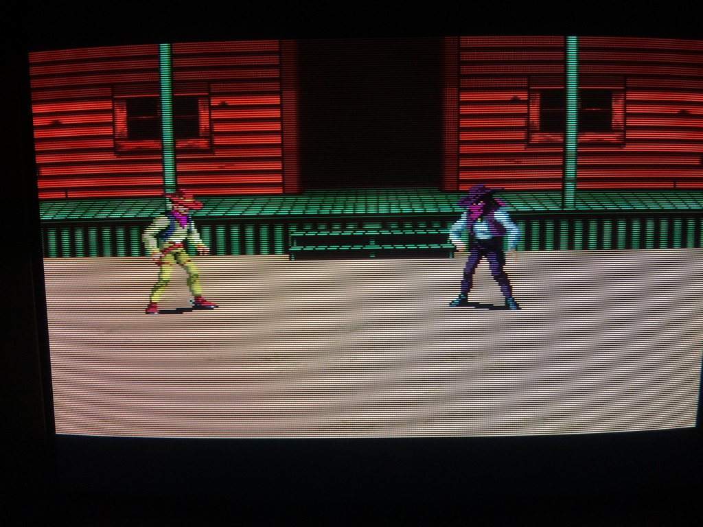
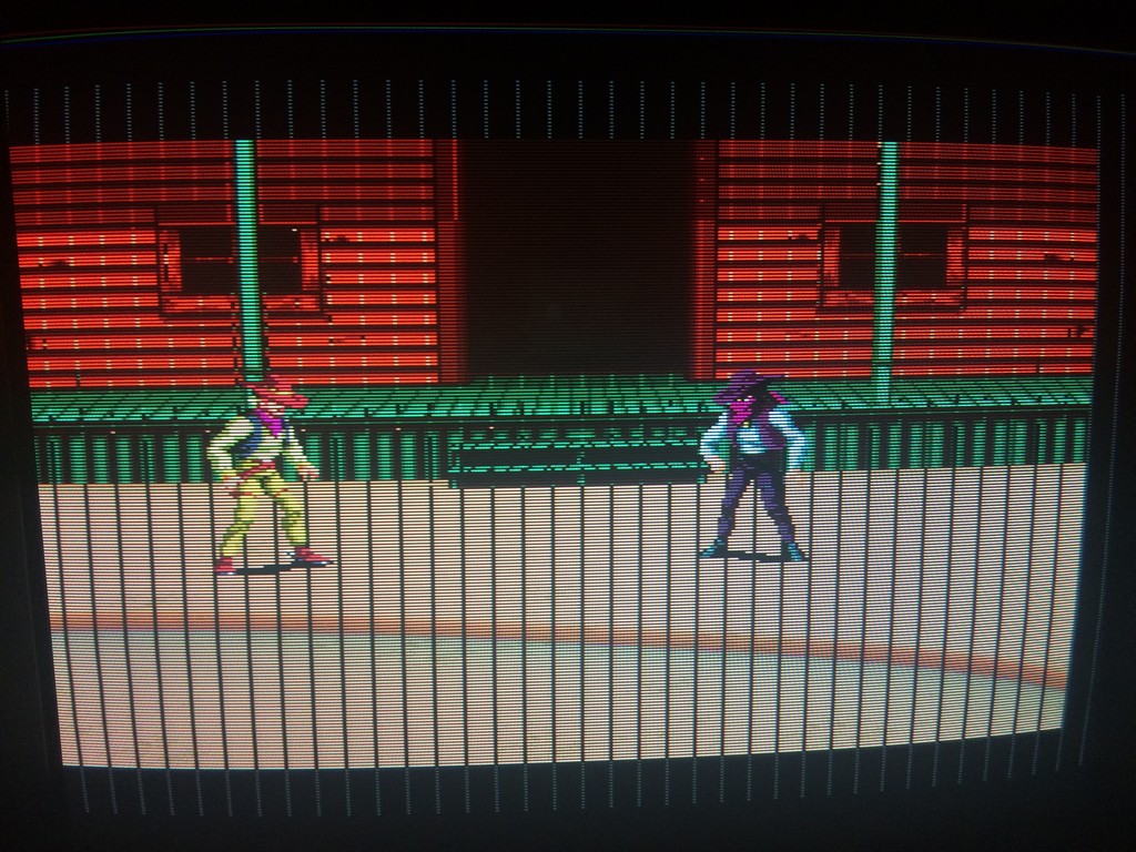
Gameplay was fine but graphics had black lines and music had a lot of white noise.

ssrider


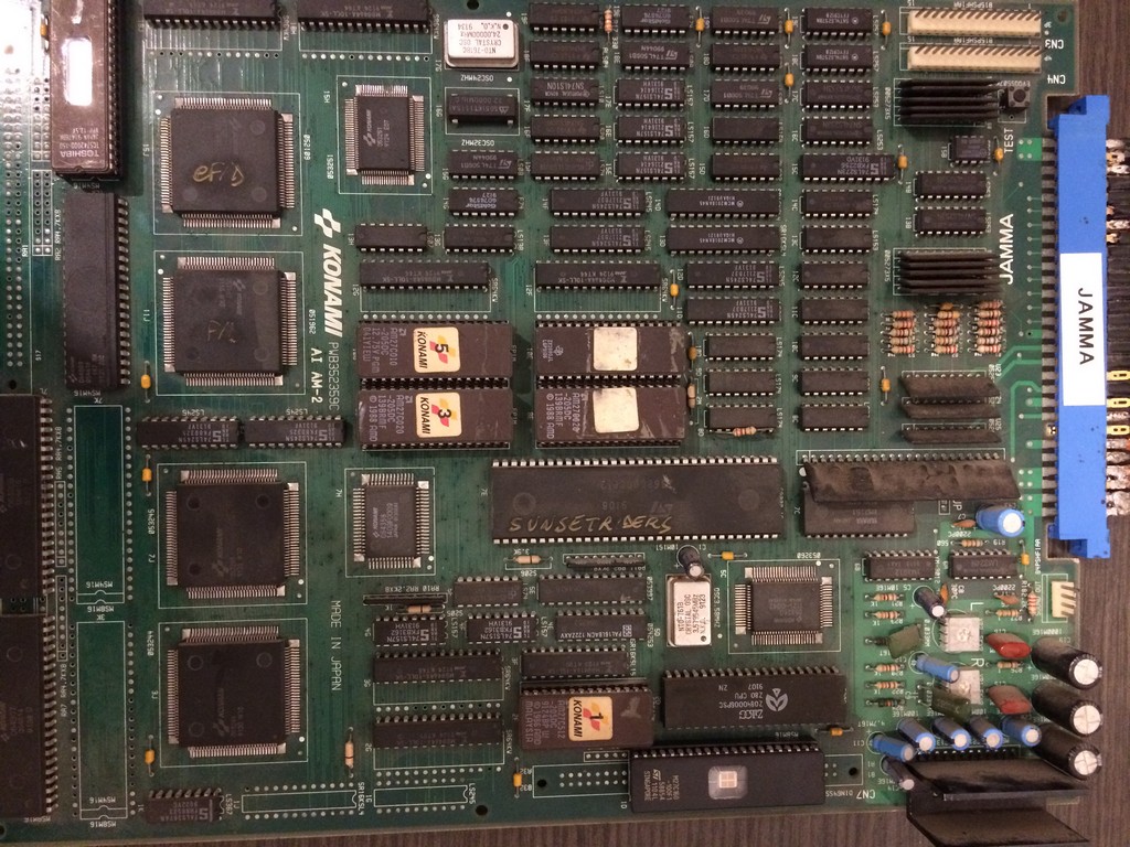
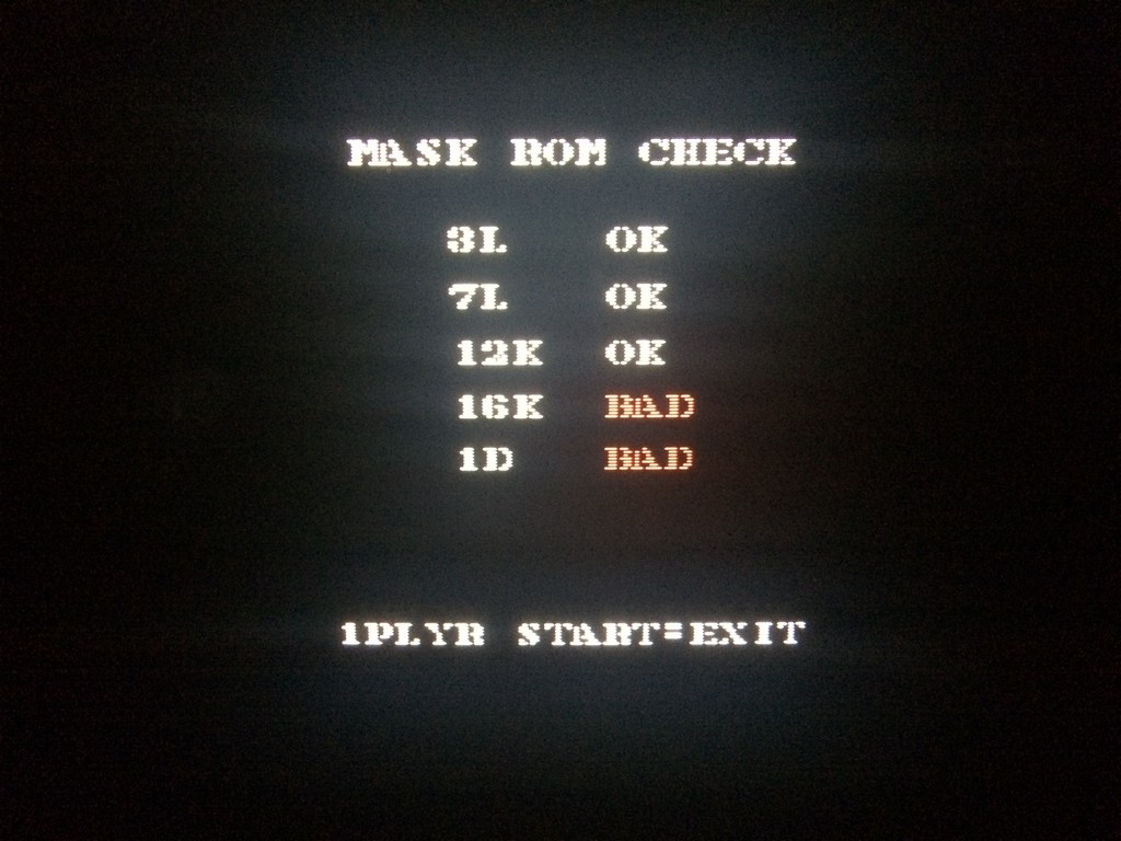
I ran the maskrom check and it reported two roms as bad, one of which was infact the rom with the sound data.


ssrider2


It doesn’t mean necessarily that the maskroms are bad, can be also that the custom chips have some pins not soldered correctly or the chips themselves being faulty.

The only way is to desolder the maskroms and check on a programmer if it reports pins not connected which means that the chip internally is broken.

After a check with the romset, I decided to dump rom 16k as 27c400 (4mbit eprom with maskrom pinout) and rom 1d as a 27c800 (8mbit 16bit eprom).

Both were reported as having pins non connected properly.

ssrider3

So I replaced maskrom 16k with a 27c400 and the markrom at 1d with a 27c160 eprom (16mbit 16bit eprom) after having doubled the original file in order to prevent the game to access the empty space in case the additional addrr line is not connected to GND or 5V.

This fixed 100% the game

ssrider4

ssrider5

May 192016
 

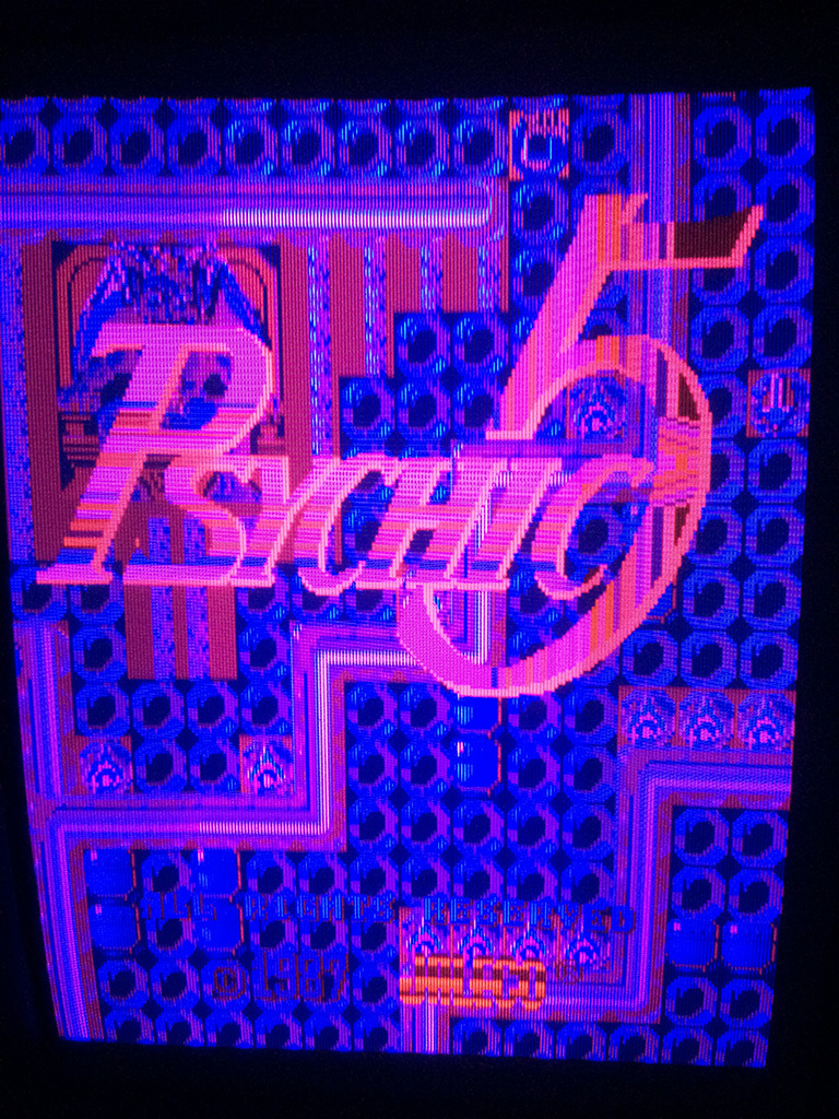
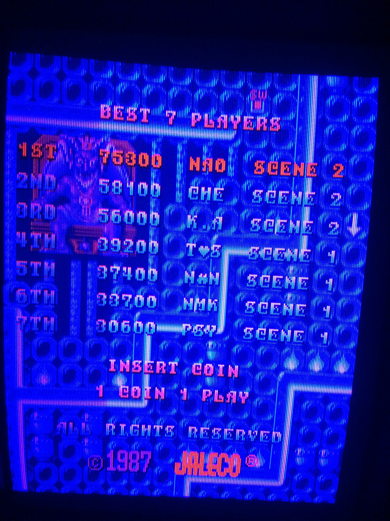
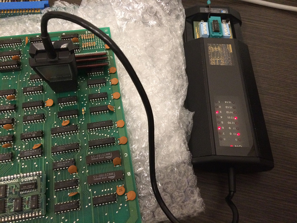
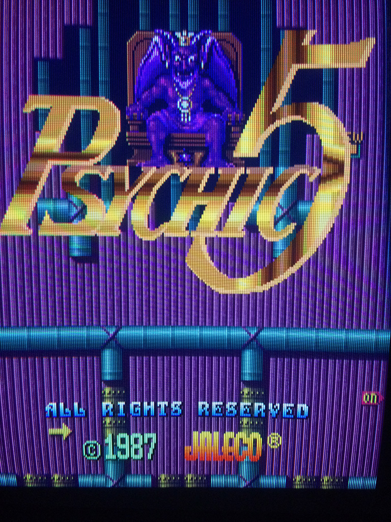
Last year after a lot of research I succeded to buy at a good price an original board of Psychic 5 , one of my favourite game of all time, which was really in mint conditions.


psychic5


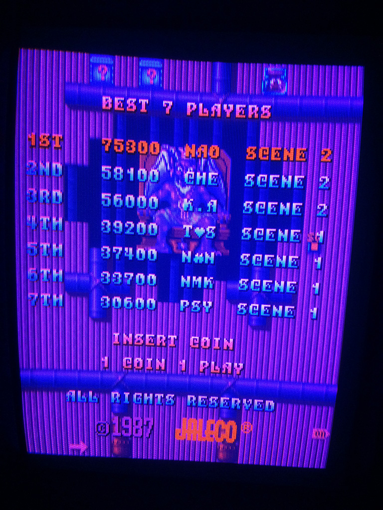
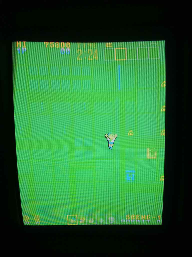
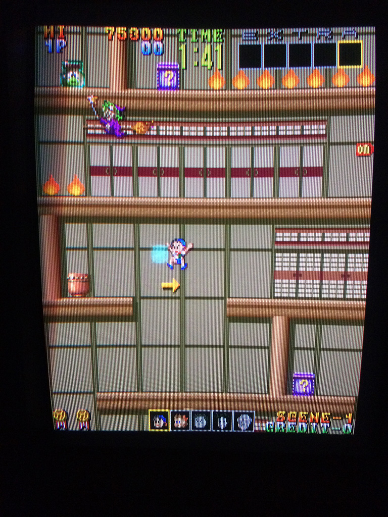
Some days ago I picked it up for a play and after some minutes the game developed this problem during attract mode:

psy5

psy3

psy2


After some more time the game was total yellowish:

psy4


Game hasn’t any schematics available and there are not any games known to me which have similar hardware and schematics available.

I could only go blind and try to find the reason of the fault.

So I started to short some signals of srams looking for palette changings and I found a couple of them at pos.6N and 6M, 16kbits.

The one at pos.6N had the first 4 data pins low and I was pretty sure either it was faulty or the 74ls245 connected to the data bits.

After desoldering, the sram 2018 was tested good in the programmer. That meant that the programmers didn’t use all data pins of the palette rams. The 74ls245 was good because it could drive correctly the signals without the ram installed.

I tested some TTLs nearby looking for strange signals but found nothing.

Decided to go brute force using my logic comparator and testing everything on the video board but starting with FUJITSU parts which are known to be very unreliable.

The logic comparator found a 74ls08 with all the outputs faulty

psy6


I double checked the outputs with a logic probe and they were all in the grey area (no good logic signal).

After changing it I fix the problem 100%


psy8

psy1

So FUJITSU brand proves once again to be really unreliable!

Apr 232016
 

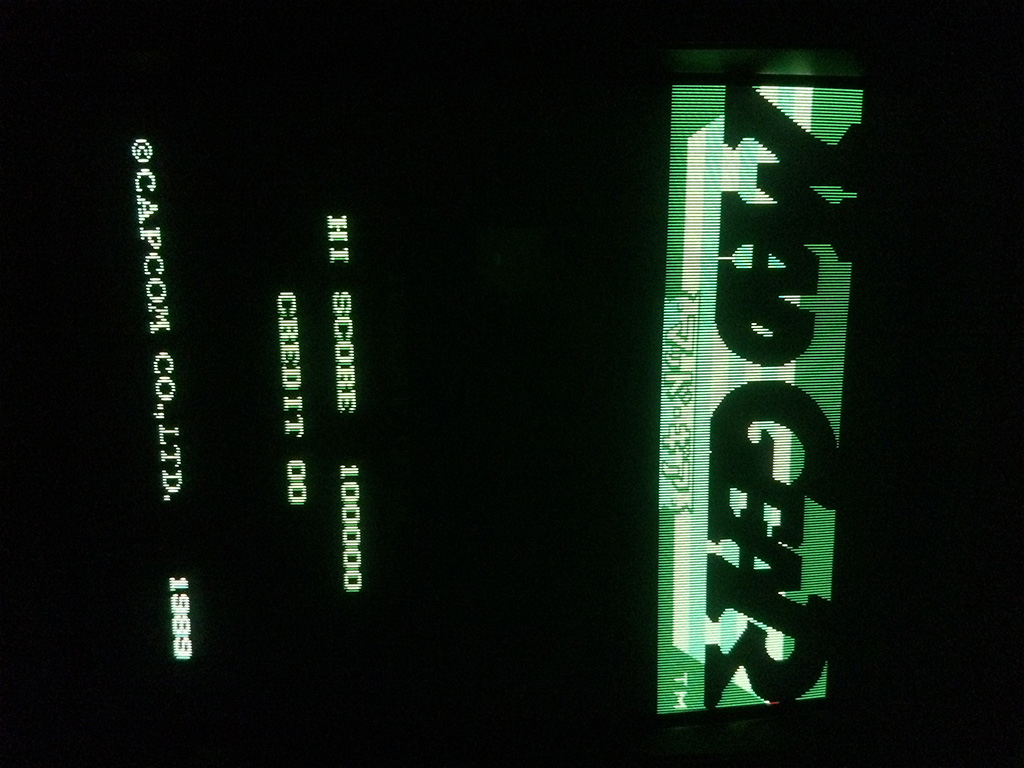
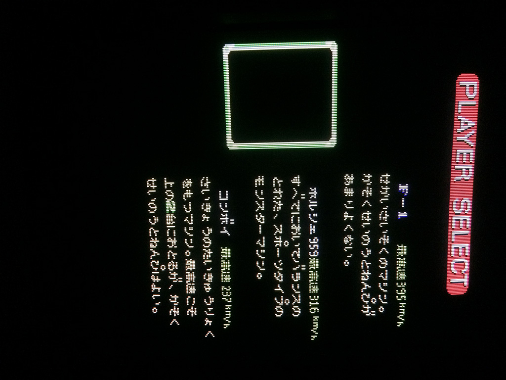
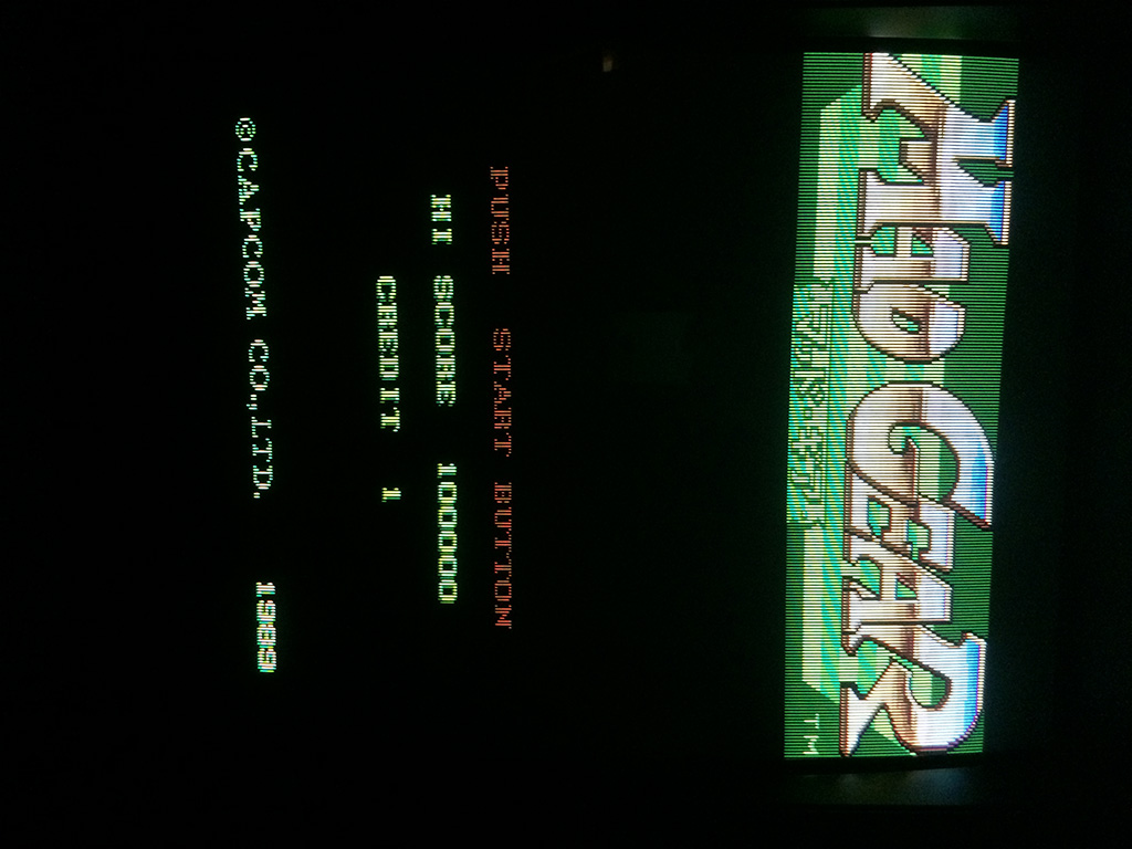
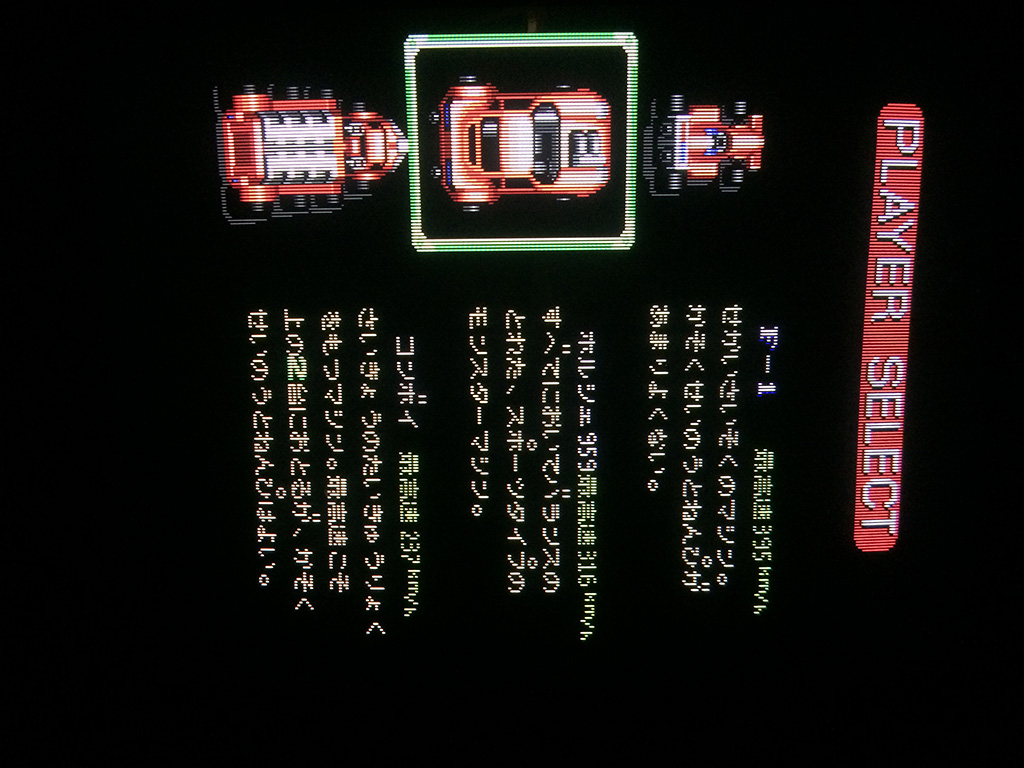
The game booted perfectly but was missing some parts of graphics , road and cars


MadG3

MadG5


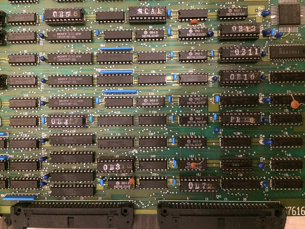
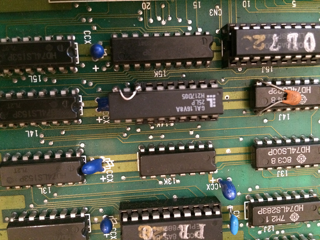
Upon closer inspection, there was a missing bprom in position 14k.

MADg8


Since I had a working Mad Gear, I borrowed the bprom and installed on the faulty Mad Gear just to see if the chip was taken away because the game had other problems.

To my surprise, with the bprom in place, the game was perfectly working with all graphics in place.

It could have  been an easy repair but bproms are discontinued since 30 years and nowadays they are nearly impossible to find empty: they are otp chips so once programmed they cannot be erased!

In any case I did a research on ebay and there was no one selling the same kind of bprom needed for Mad Gear which is a 82s129 (equal to 6301 or 7052, depending on the manufacturer).

Next step was to find a way to reproduce it.

Bproms have small capacity but they have a fast access time (less than 50ns) and for that reason they are used often for decoding graphics.

Some OTP roms, such as 27256 or 27512 , have fast access times and can be used in place of bproms by just burning the binary file into them but the problem is that you have to build an adapter because the pinout is different and also the size of the chip itself is much bigger.

The other solution , more elegant and less invasive , is to reproduce the content of the Bprom into a GAL (Generic array logic). This has been done before by other people to reproduce some bproms but they had programming skills which I don’t have.

My friend Caius some months ago pointed me to a blog of a guy who programmed an alternate software for the TOP2005 chinese programmer which had also the ability to produce equations for a GAL out of a  bprom file.

Turned out that this was exactly what I had been looking for!

So first of all I would like to give full credit for this wonderful program to the guy who goes by the name of Elgen.

His blog is: https://elgensrepairs.blogspot.dk/

Facebook page: https://facebook.com/ElgensRepairs

Most important the software to convert bprom to GAL equations can be downloaded from here: https://bitbucket.org/Elgen/u2pa

Now back to the problem: my wish was to reproduce the bprom into a gal without building an adapter.

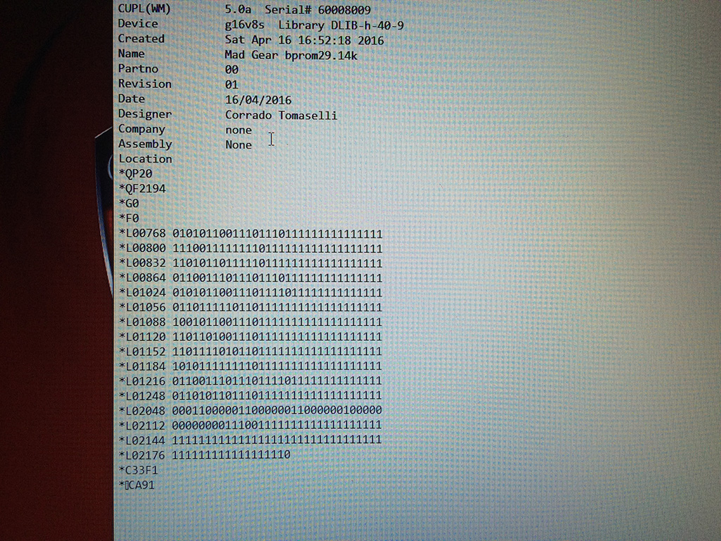
So I ran Elgen program on the bprom file taken from Mame which produced the GAL equations.

I then started the program WINCUPL by Atmel (can be downloaded free from here: https://www.atmel.com/tools/WINCUPL.aspx ) in order to produce the JED file (fuses list) out of the PLD equations (source code)  so that a programmer could burn the GAL chip.

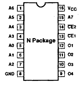
On the WINCUPL program I declared the inputs (addresses) and outputs (datas) in the same pinout standard of the original bprom chip so that I could avoid bulding an adapter:

82s129

We don’t have to worry about CE1 and 2 because normally they are tied to GND

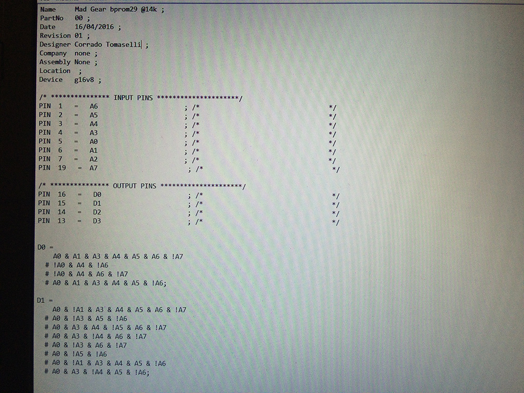
After copying and past the equations produced by Elgen program into the PLD project of WINCUPL and minimizing the equations using Expresso algorithm I got this:

MadG2

Since the equations were not complex in this case, I could use the smaller 20 pins GAL chip, a 16V8 instead of the bigger 24 pins 22V10.

You can see that the GAL file used only 2 data lines instead of the 4 of the bprom file.

At this time you can notice that the BPROM chip is only 16 pins while the GAL 16V8 is 20 pins.

After compiling succesfully I got my JED file to be used in a common programmer supporting PLD files:

MadG


With the way I declared inputs and outputs, I could install the GAL chip on the socket, leaving out 4 bottom pins.

In order to power it, I only needed to solder a jump wire from pin 10 to pin 8 for the GND! Very easy and less invasive!


MadG4


Now the smoke test:

MadG6


MadG7


Game fully restored!

Again I would like to thanks Elgen, without his program I couldn’t repair this game, but more over, it’s a very important tool for everyone who has missing or broken Bproms because they are really near impossible to find empty nowadays


The New Zealand Story (bootleg) repair log

 PCB Repair Logs, Repair Logs  Comments Off on The New Zealand Story (bootleg) repair log
Apr 172016
 

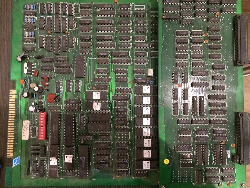
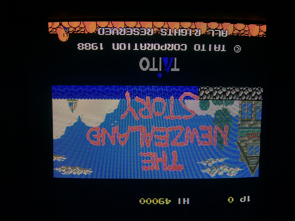
Got this ugly bootleg for a repair.

TNZS2


Game had no sound and the jump button didn’t work.

First of all, this bootleg is known to have the picture upside down and I wonder why the bootleggers left the game in this state.

TNZS


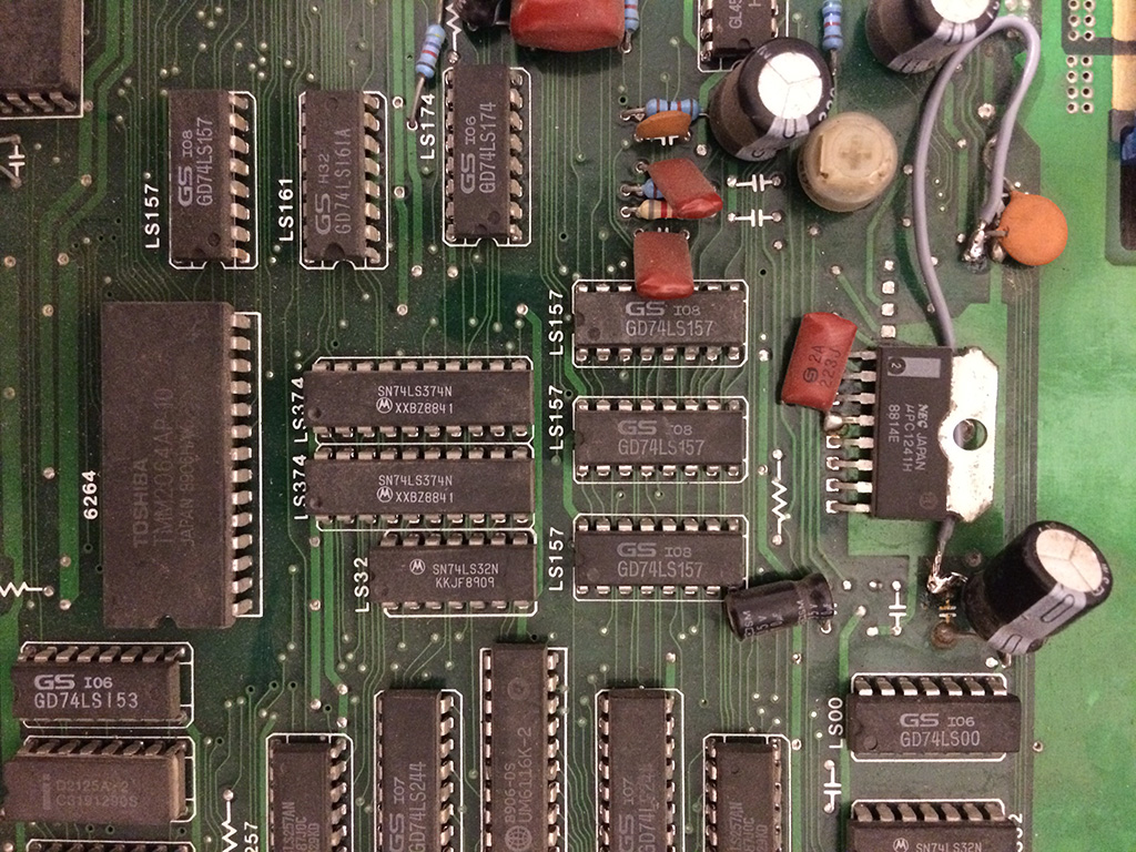
Since I had no white noise from the amp I checked the circuit near it and found a capacitor with a leg desoldered. Unfortunately the hole was completely rusted and I had to run an ugly wire to another point on the pcb to restore the sound.

To do: find a thinner wire 🙂


TNZS3


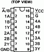
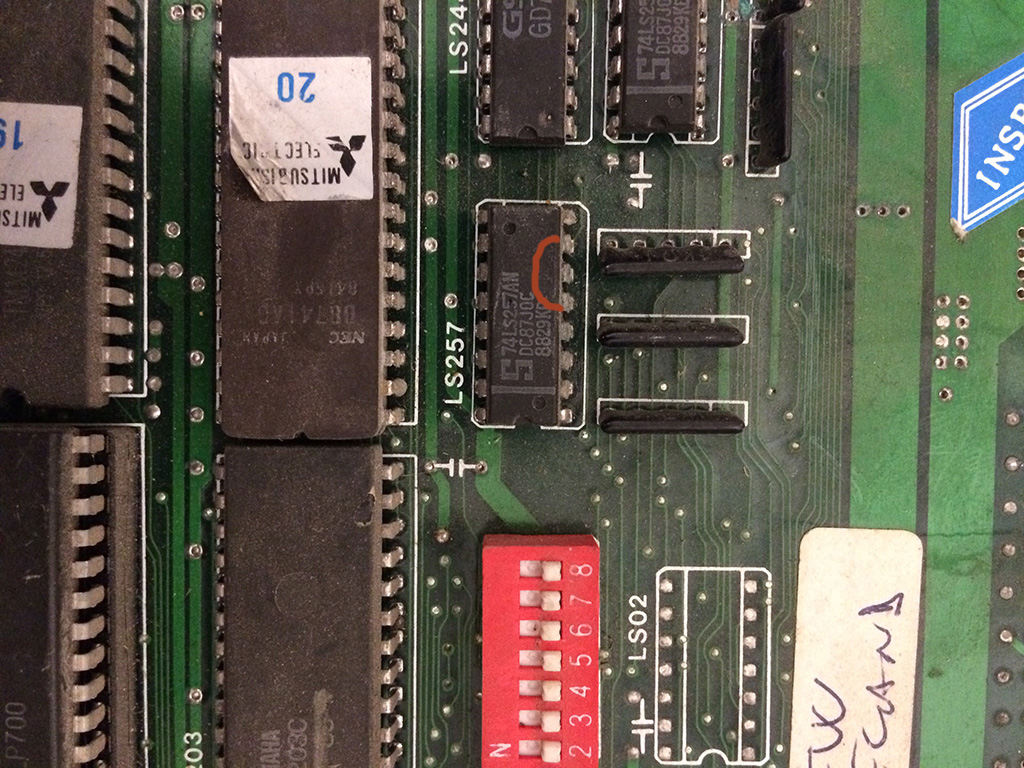
For the “Jump” problem I traced back from pin 23 of the Jamma connector to input 2A of a 74LS257 multiplexer.

The jump button of the second player, was connected to input 2B of the same 74LS257.

So those buttons has the ouput 2Y of the 74LS257 in common, so to check if the TTL  was working correctly, I ran the input test with the second joystick and infact also the second player jump was not working. The output 2Y was oscillating but evidently not in a correct way.

sn74ls257_s

Given that the game has no first player and second player  playing at the same time, I opted with a simple but effective solution: I shorted 2A and 2Y togheter so that the first player button was connected directly to 2Y.

In this way when you press first player button you press also the second player one but for TNZS is not a big deal because you never play a co-op game 🙂

TNZS5


With this solution I could fix the game without bothering to replace the ttl chip

Thunder Hoop repair log

 PCB Repair Logs, Repair Logs  Comments Off on Thunder Hoop repair log
Apr 172016
 

Game showed a static white screen at boot.

Checked the clock and it was fine, then I checked if the 68000 was reset correctly and found out that it didn’t get any reset signal.

Tracing back I came to a capacitor which had a leg unsoldered.

ThunderHoop


After fixing it, the game booted correctly

TH


I started a game but I soon noticed that it the pcb played sometimes random or wrong music/sfx.

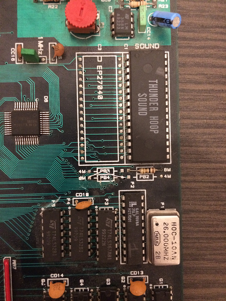
The game has no FM chip, so the OKIM6265 is responsible for music and sfx and there is only one soundrom.

Checking the circuit in detail I noticed one jumper for selecting 8Mbit rom was broken in half.

After resoldering a new one, the music and sfx was restored correctly.

Thunderhoop2