Caius

1942 double repair log

 PCB Repair Logs  Comments Off on 1942 double repair log
Jun 272019
 

I had a couple of original Capcom ‘1942’ PCBs lying around which I never tested due to the lack of a proper JAMMA adapter (game uses an unique pinout which is not the Capcom Classics one).Recently I had chance to build the adapter and try the boards out, it turned out both were faulty.

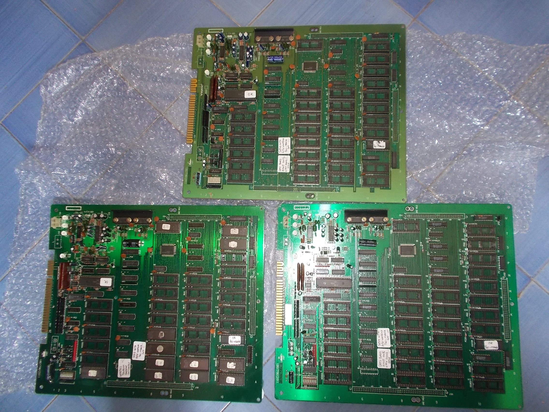
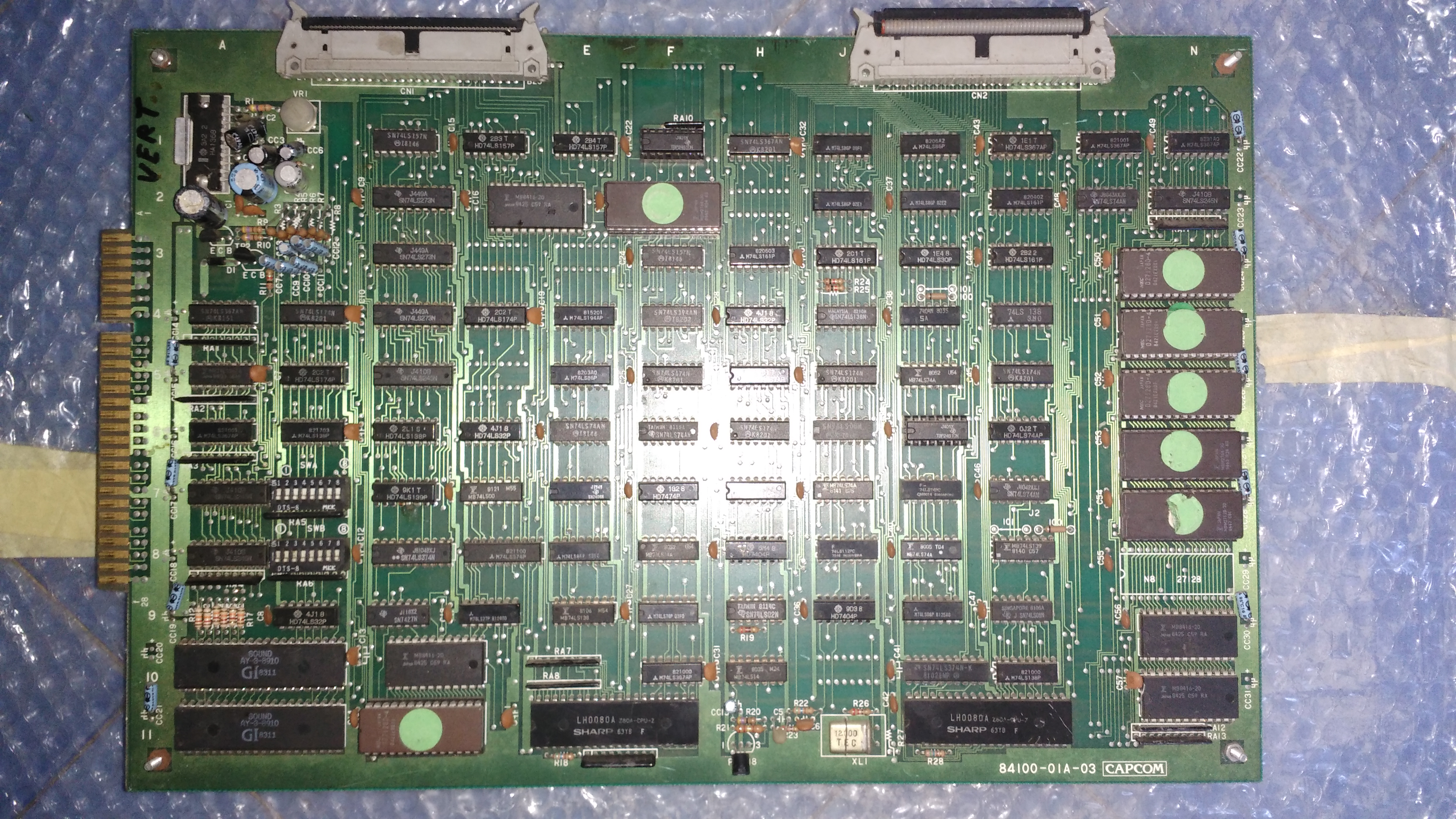
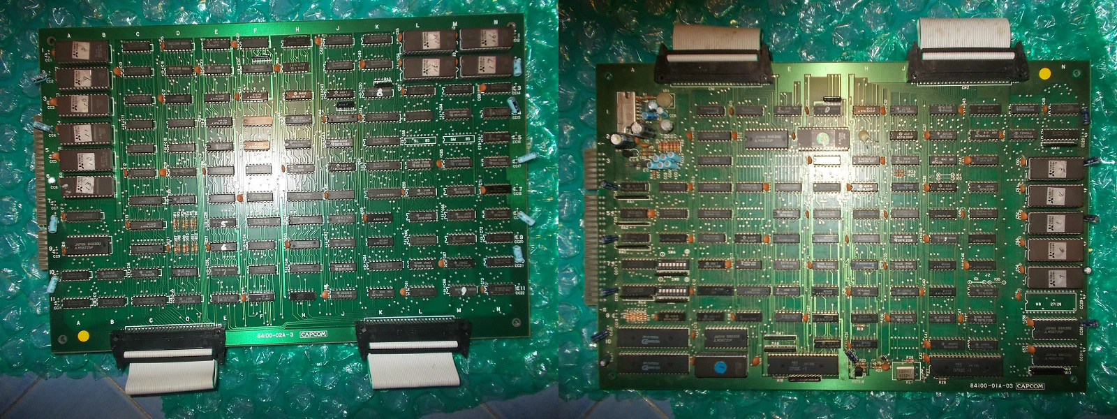
The first set was in good shape in its CPU board :
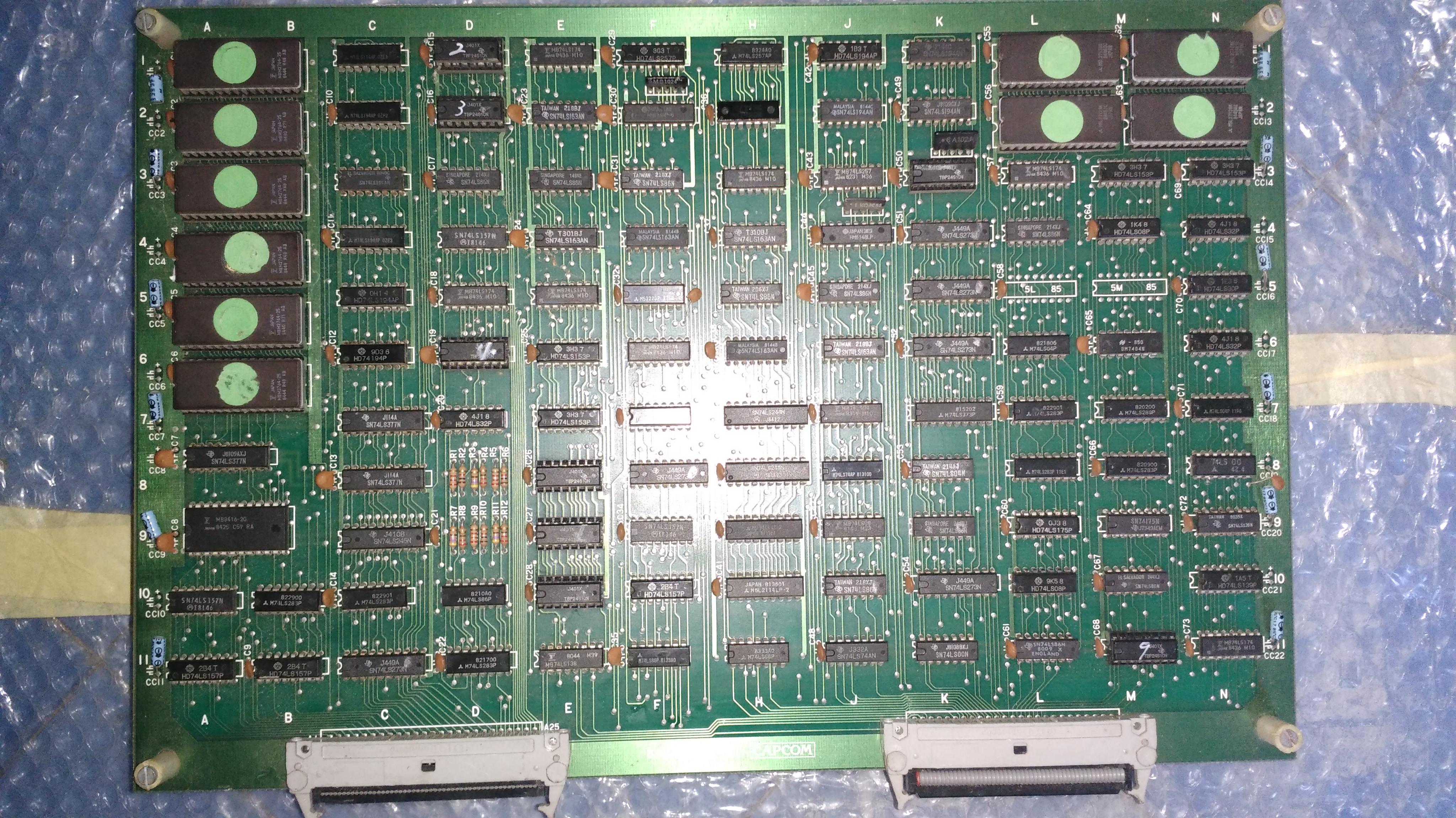
And VIDEO board:

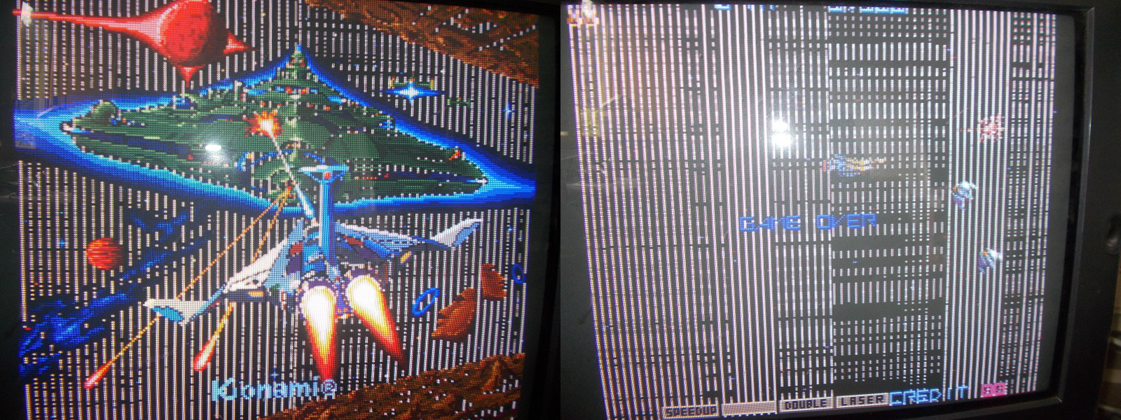
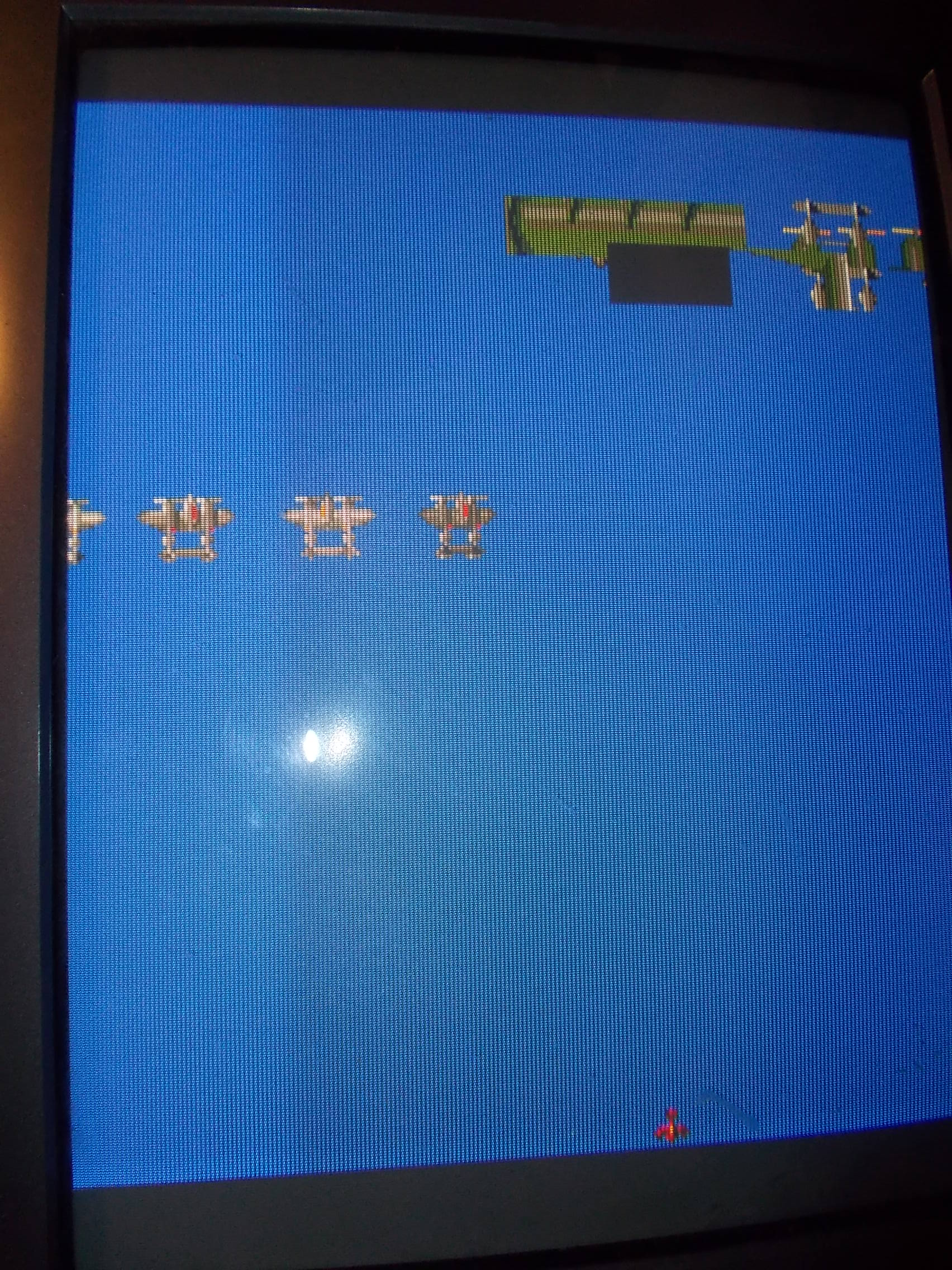
It even booted up and played with sound too but sprites (planes) were totally absent:

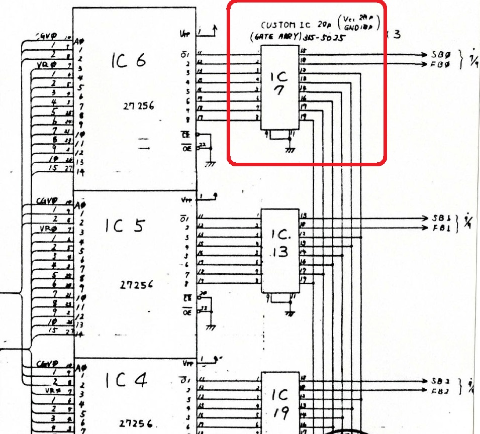
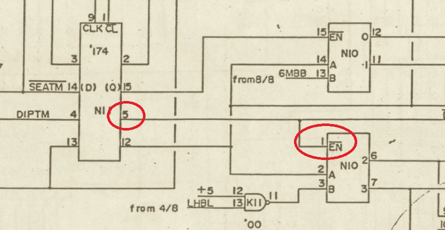
The faulty was obviously located on VIDEO board so I went through schematics and found a part of the object circuit highlighted with an handwritten note saying “NO PLANES”

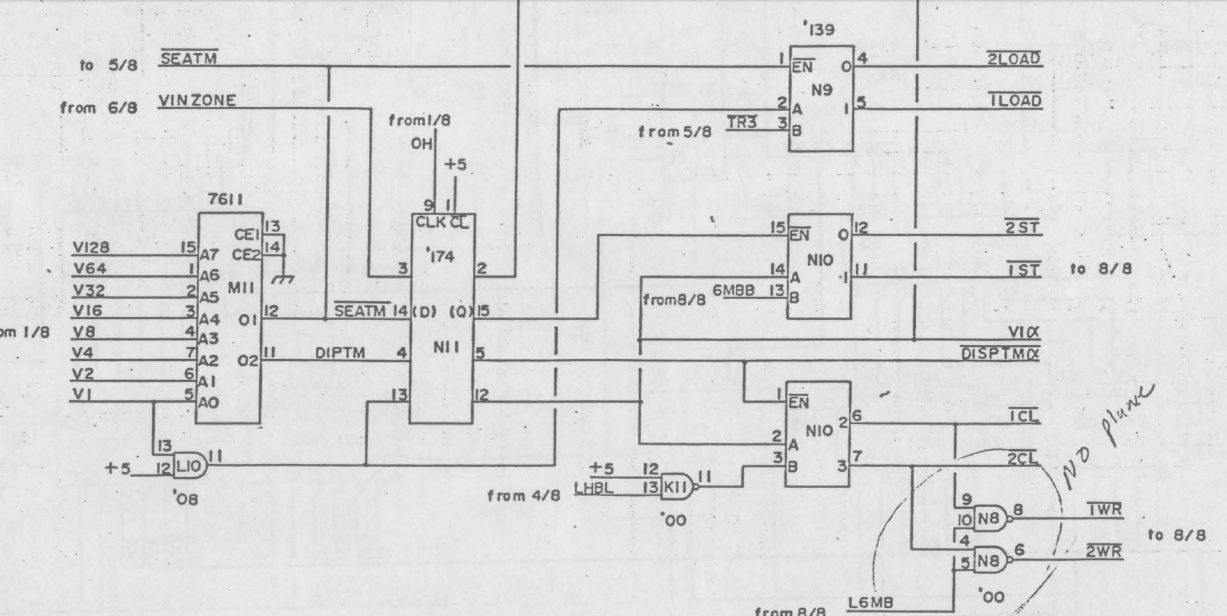
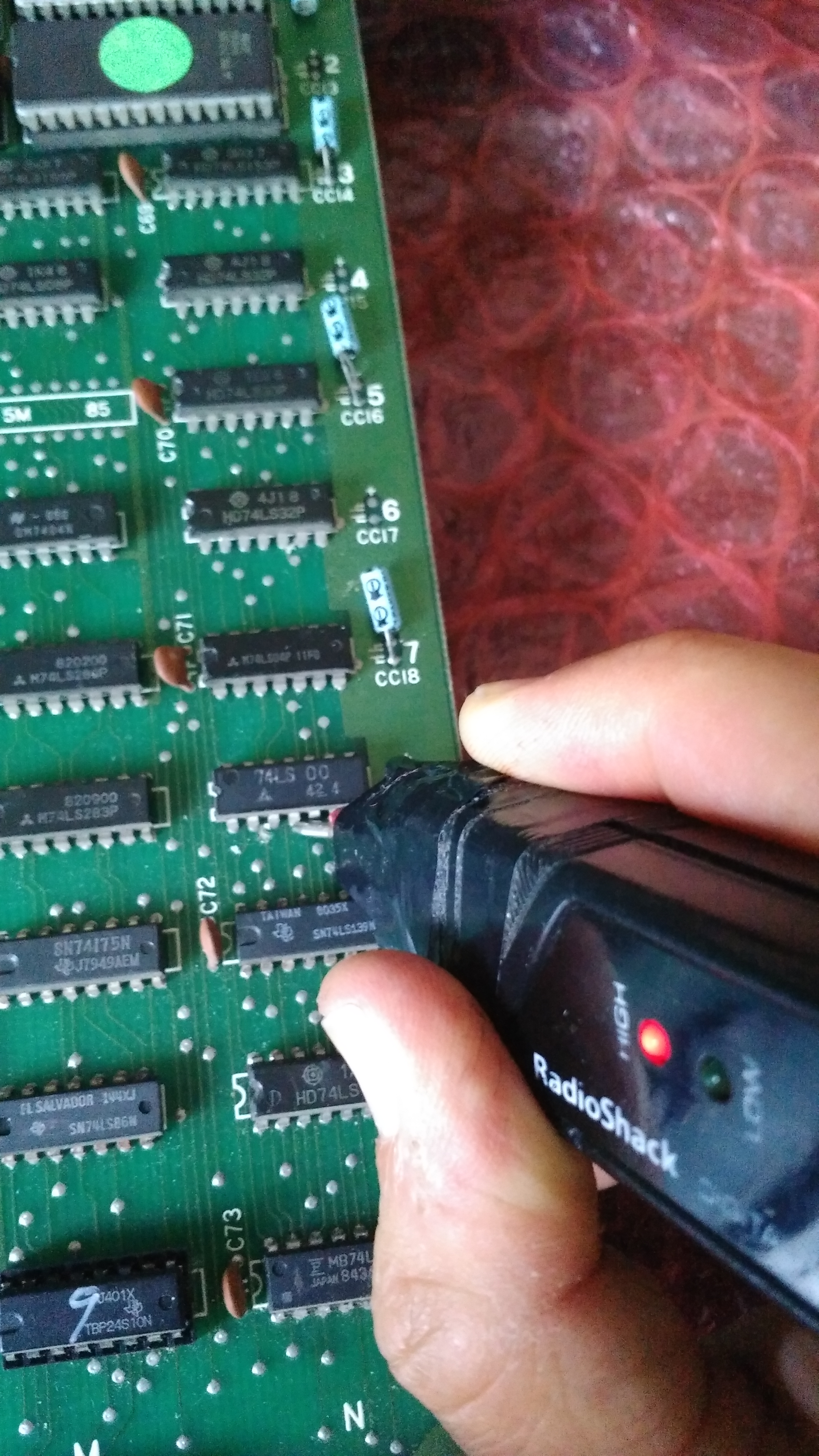
The circled section concerned two NAND gates of a 74LS00 @N8 which generates two signals labeled ‘1WR’ and ‘2WR’.When I probed the inputs I found pin 9 and 4 stuck HIGH:

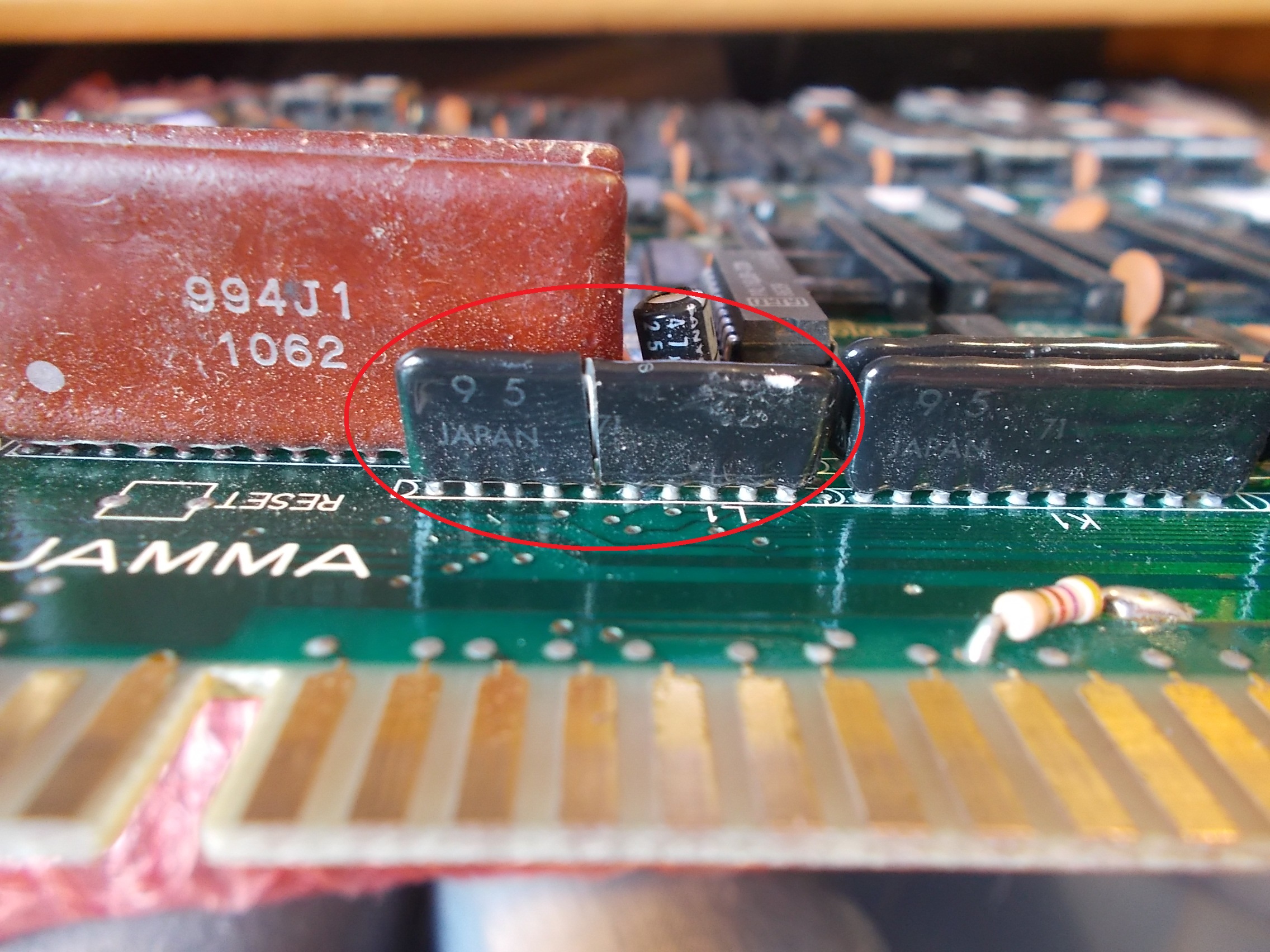
These inputs come from outputs of a 74LS139 @N10 which had its pin 1 floating:

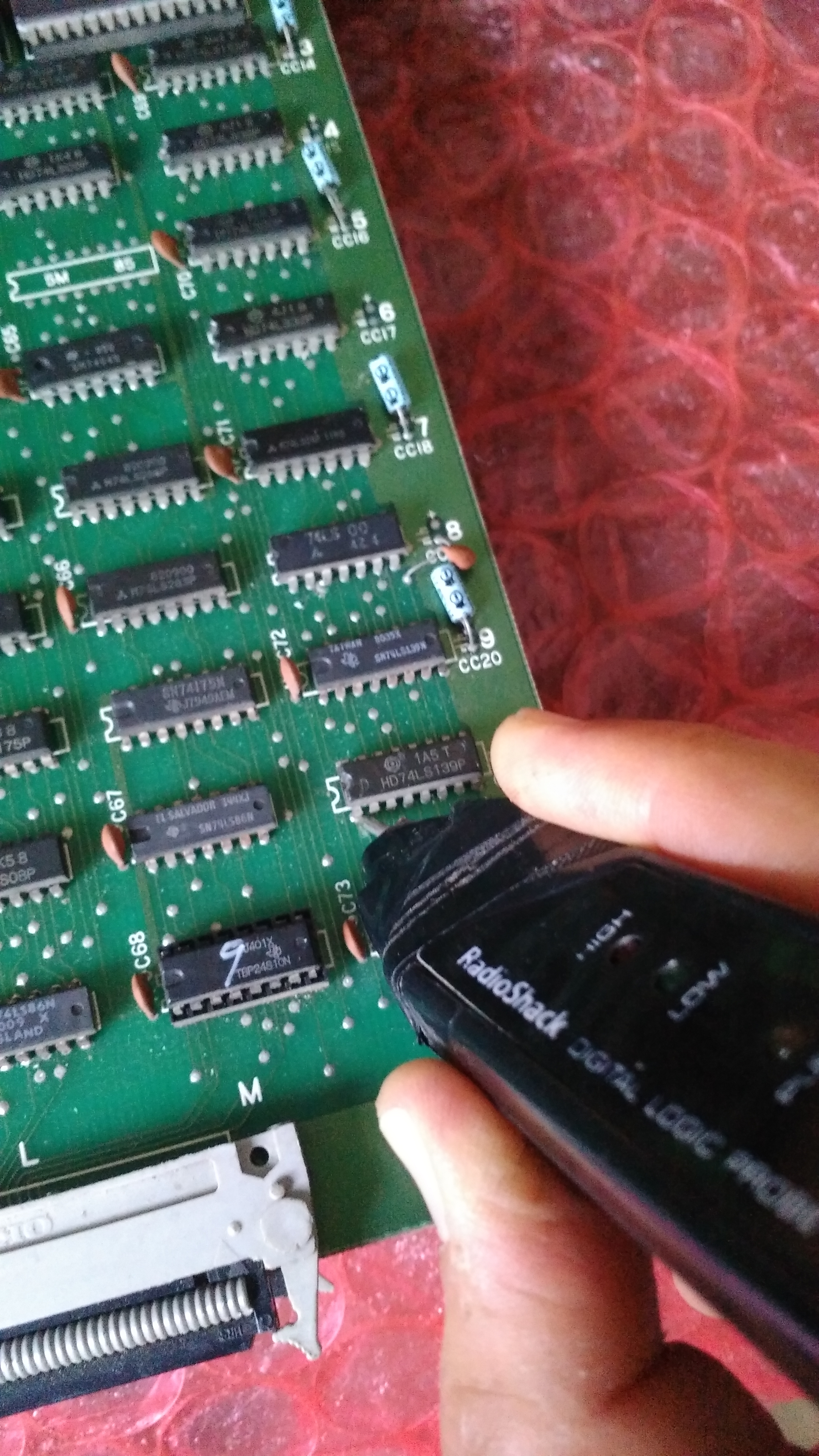
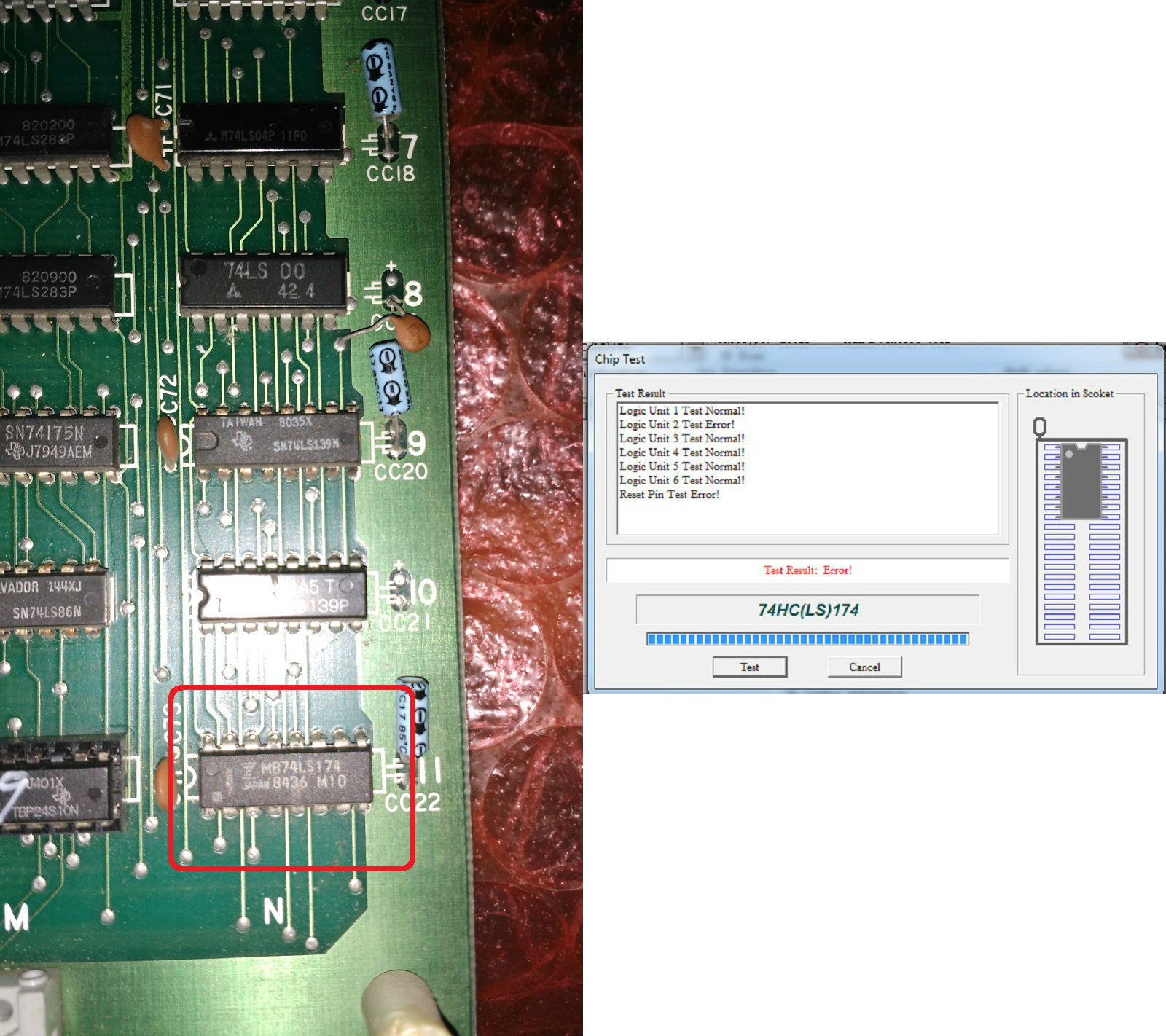
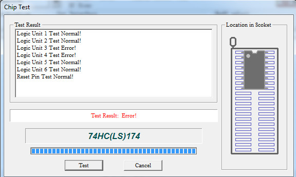
Pin 1 is the enable input of the decoder and comes from output pin 5 of a 74LS174 @N11 :

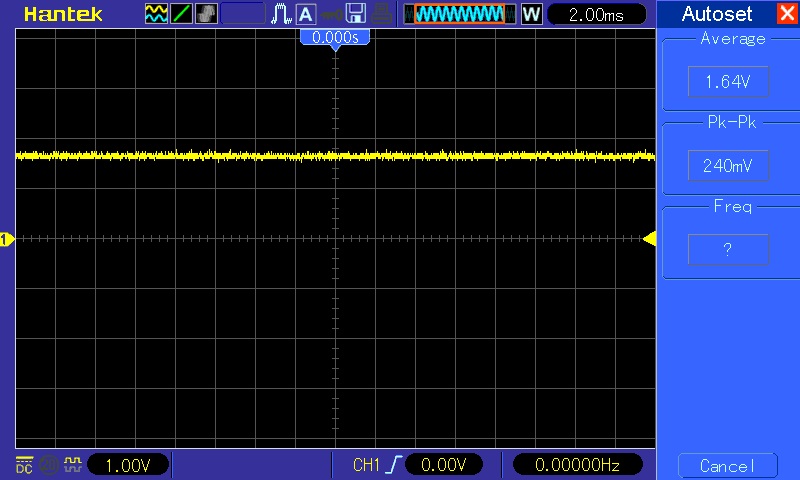
Pin 5 of this 74LS174 was indeed floating, stuck at undefined voltage level of +1.64V :

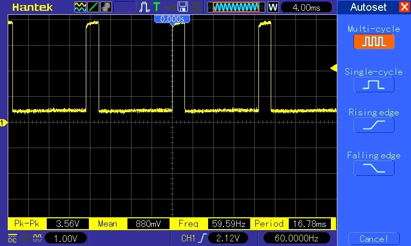
But the input pin 4 was active :

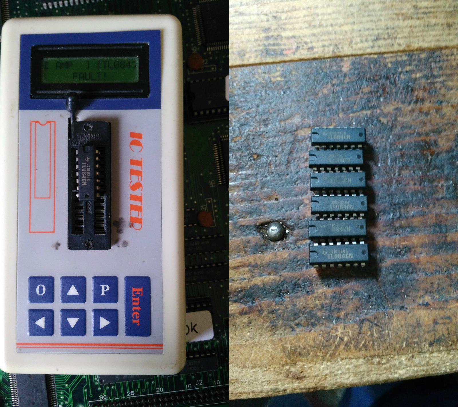
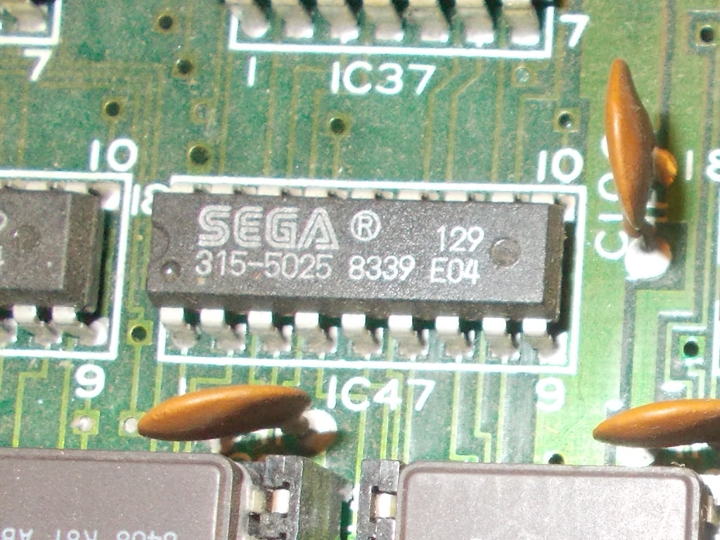
This is a typical way of failure of Fujitsu TTLs and the part was from this manufacturer hence , sure enough, I removed the chip.It miserably failed the out-of-circuit testing:

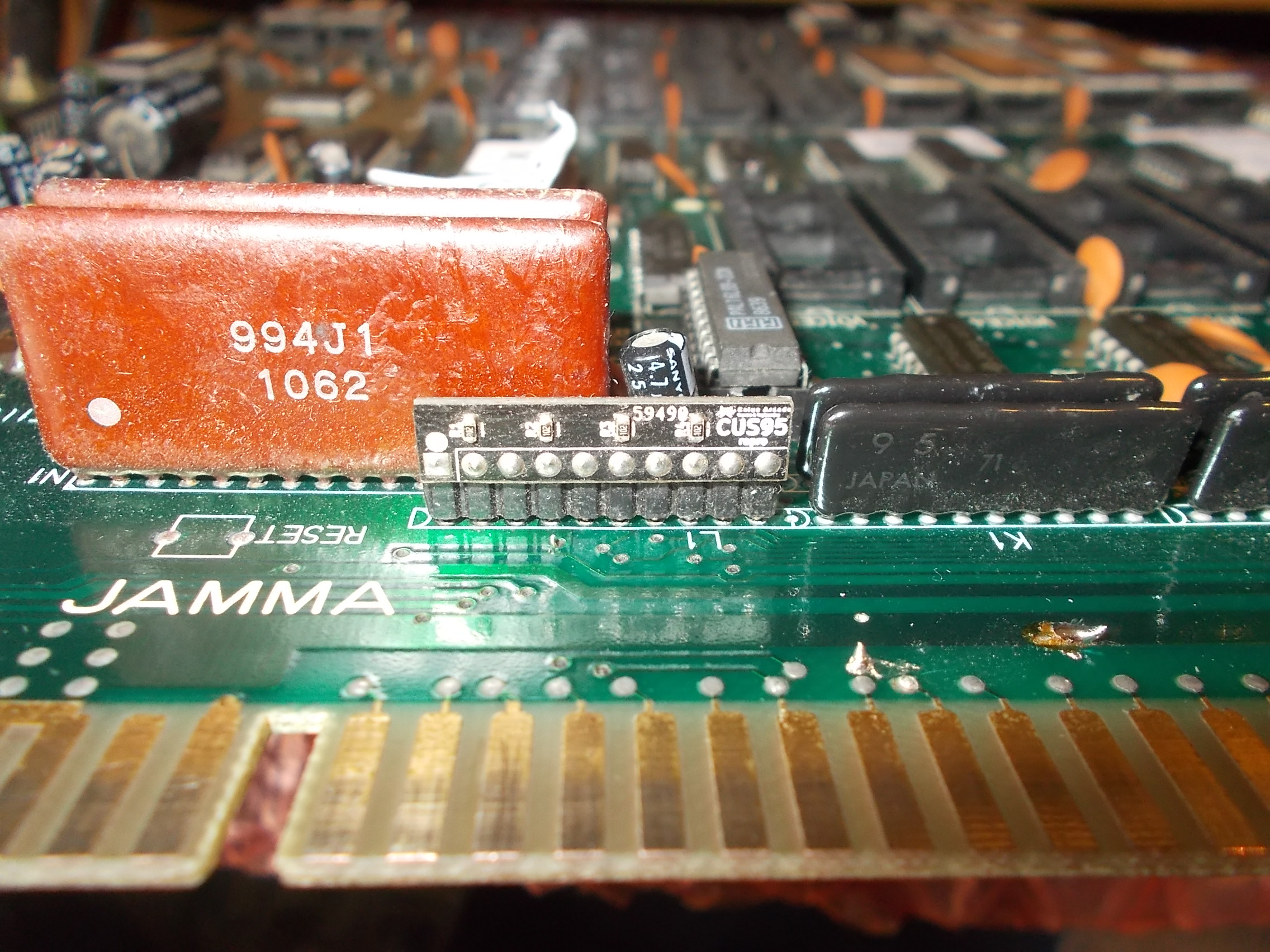
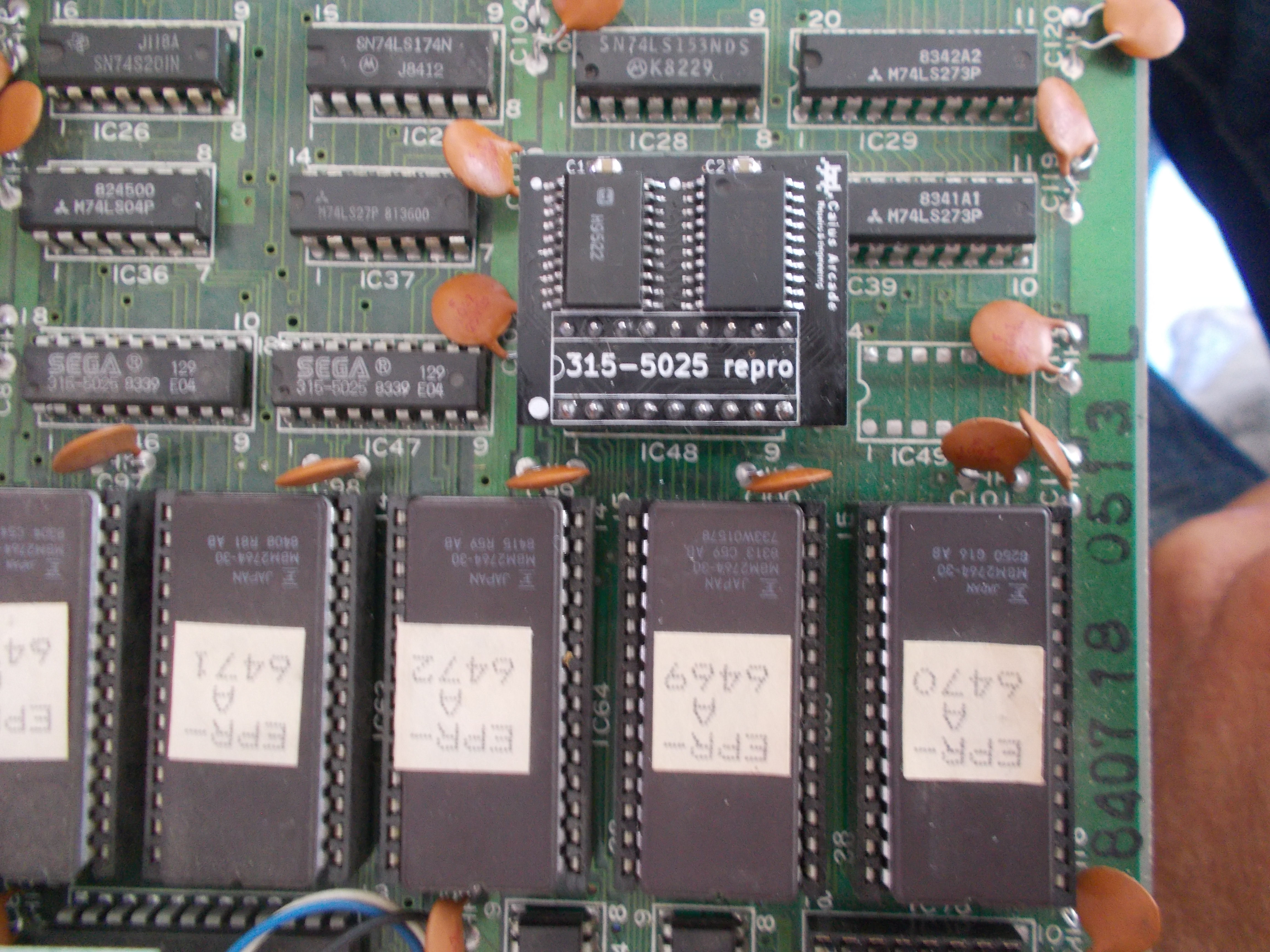
Replacing it restored the sprites :

First board fixed.


The second set was in good shape too :

But it booted to a static garbage screen :

Probing the Z80 main CPU revealed clock input (pin 6) was stuck high:

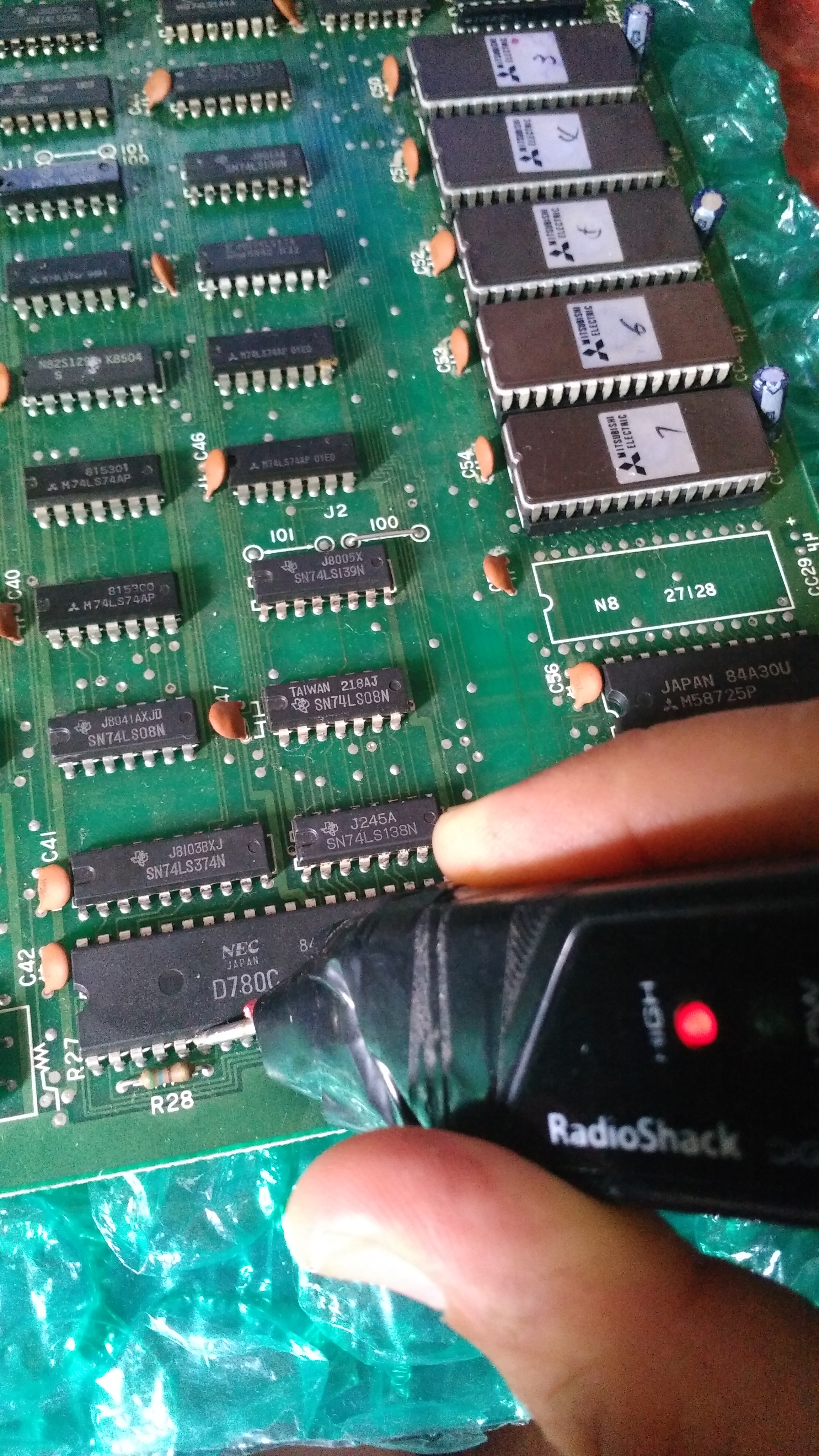
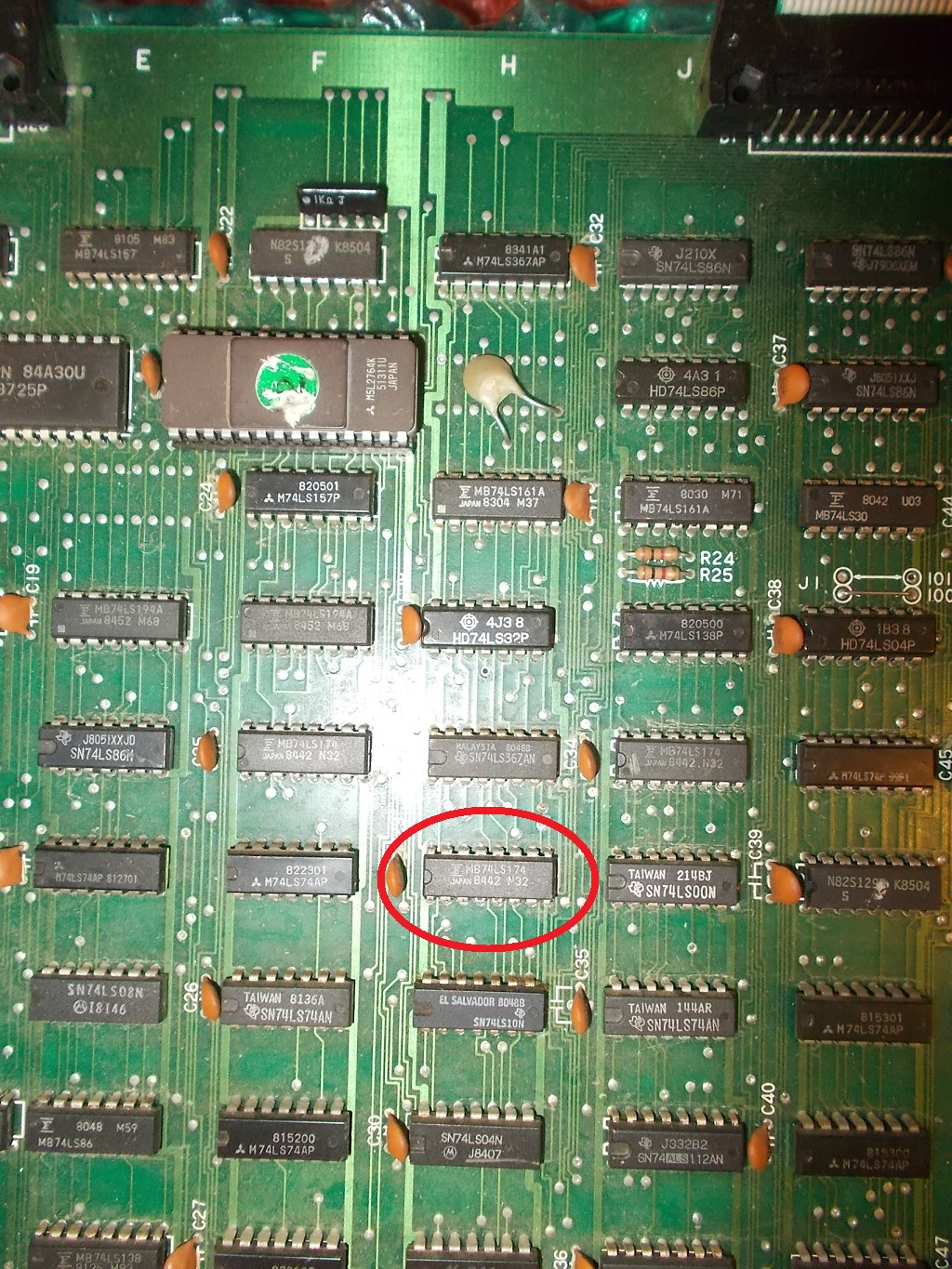
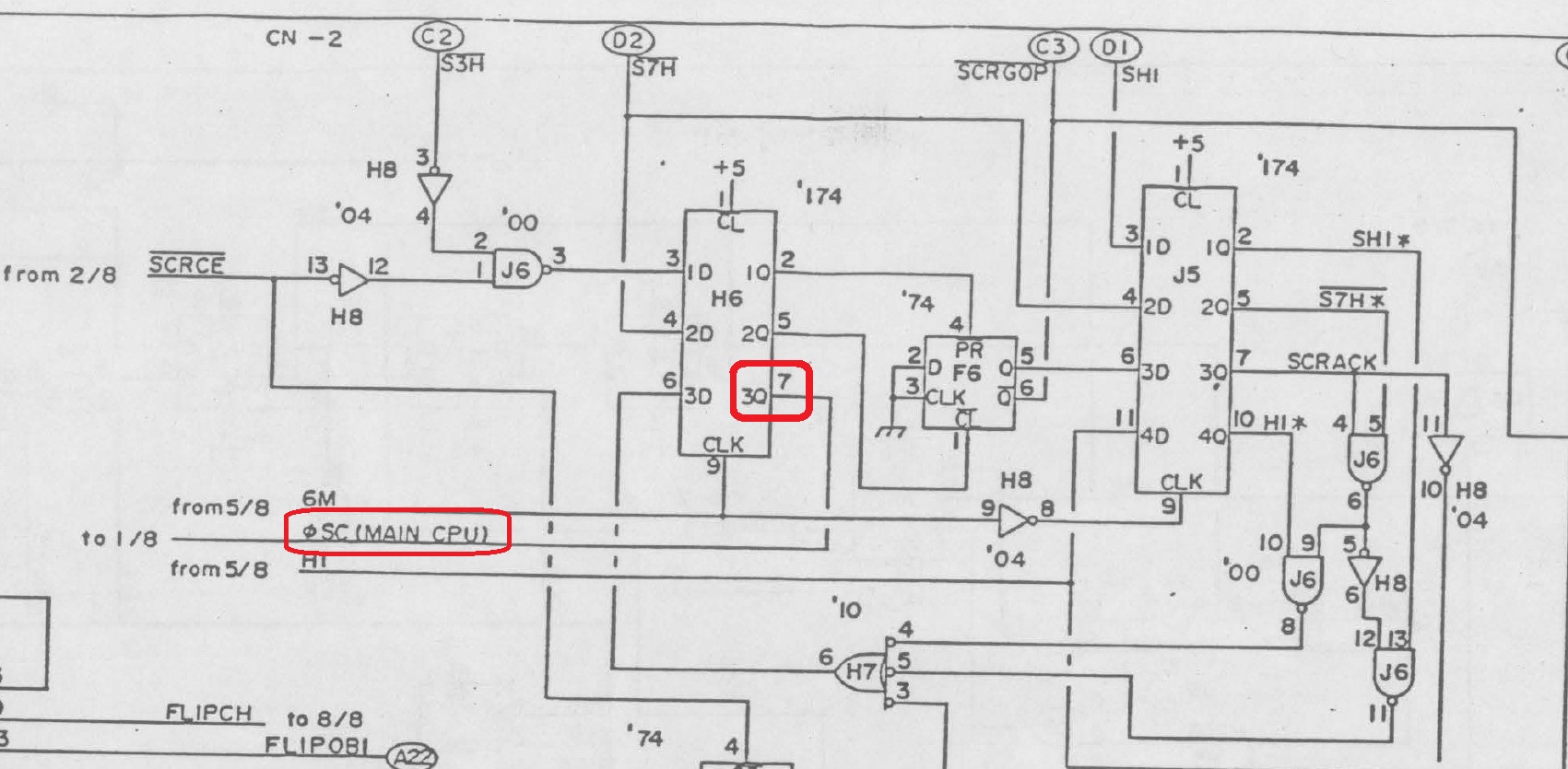
With the help of schematics I traced the clock input back to pin 7 of a 74LS174 @H6 located on CPU board, chip was again from Fujitsu :

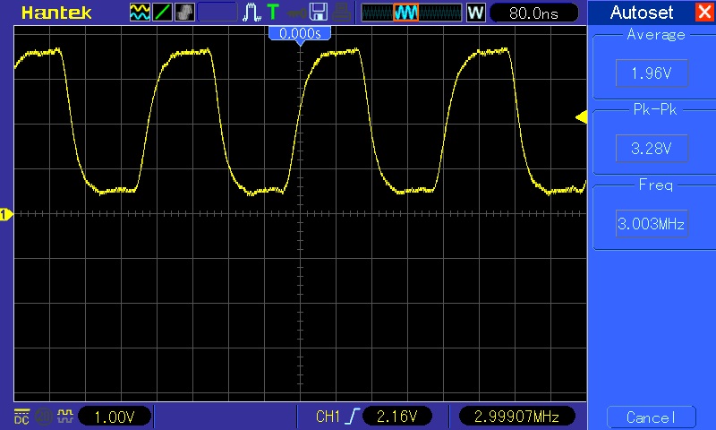
Input pin 6 was correctly receiving a 3 MHz signal:

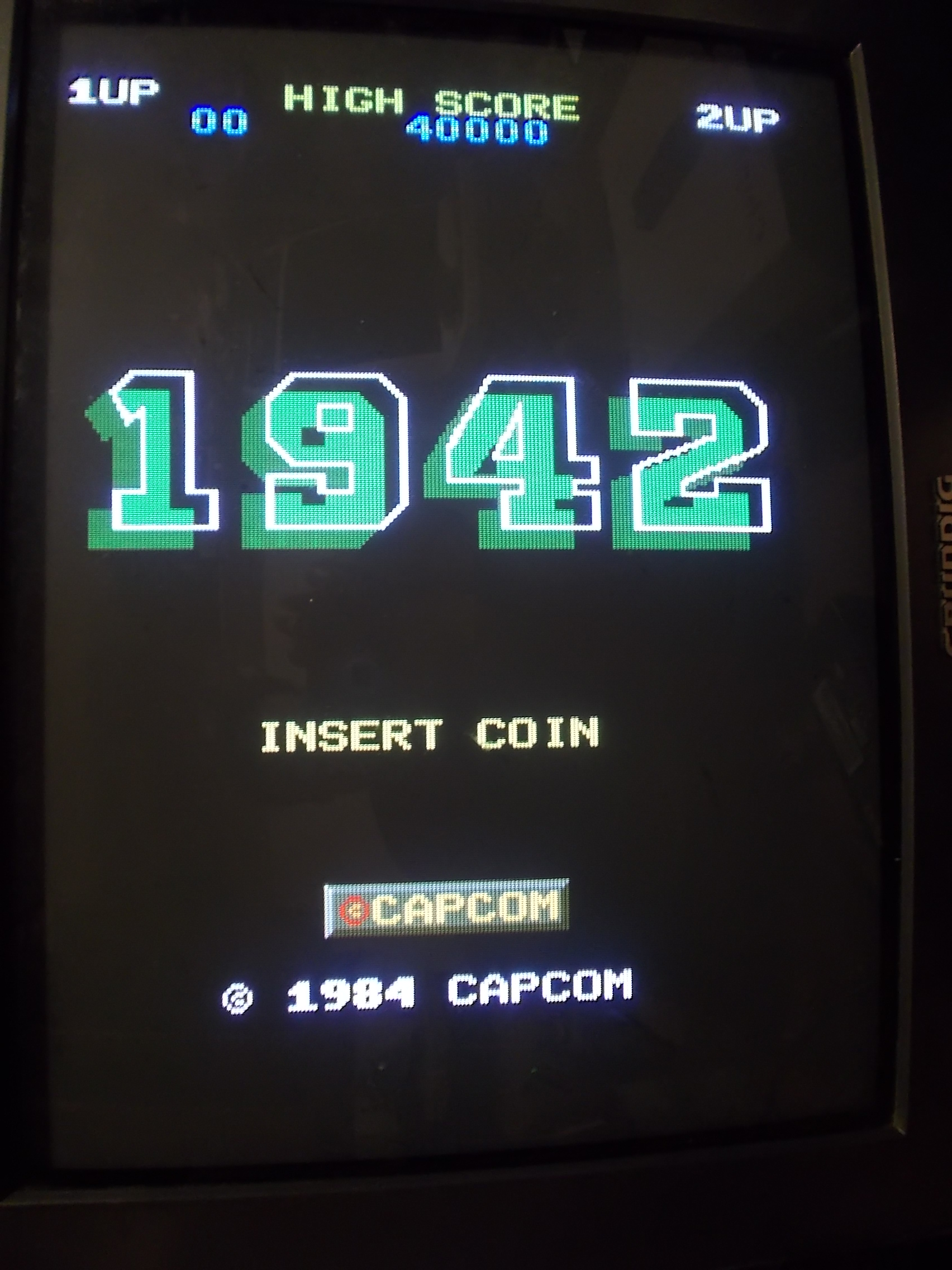
I made piggybacking with a good known IC and board succesfully booted into game:

Chip obviously failed the out-of-circuit testing:

Replacing it fixed board completely.Double repair job done.

 Posted by at 11:08 pm

Namco System 1 ROM boards repair log and ‘CUS95’ reproduction

 PCB Repair Logs, Reproductions  Comments Off on Namco System 1 ROM boards repair log and ‘CUS95’ reproduction
Jun 072019
 

Recently I received a pile of faulty Namco System 1 hardware.I’ve been sent boards grouped by type because, as you may know, it’s a complex system made of a smaller CPU board and a bigger ROM board.I started to troubleshoot the latter.Three of them were tagged as “working but with sound issue” when tested with the same Pac-Mania ROM set :

The issues went from corrupted sound to lack of some music tracks :

Using an audio probe I figured out the sound was properly coming out the YM3012 DAC but then got corrupted before being amplified.In the middle there are two TL084 quad OP-AMPs :

This part is well known to be very prone to failure especially the ones made by Texas Instruments manufacturer like in this case so I removed them all and they failed the out-of-circuit testing :

Replacing them with good ones restored full sound but while I was testing the boards I noticed some inputs were not working on one.A quick visual inspection revealed this :

The custom resistors/capacitors array marked ‘CUS95’ was cracked in half.Not having a spare I decided to analyze the part and reproduce it :

Three boards were fully functional now.The last one had also other issues besides sound not properly working as most of graphics were missing replaced by garbage,  sprites were barely visible :

The tilemap generation is handled by the custom ASIC ‘CUS123’ (plus the ‘CUS133’ on CPU board) which generates the addresses to the character ROMs:

It was most likely faulty so I replaced it :

This restored the graphics and left me with the sound issue to fix, music were completely missing on this board:

Replacing the two TL084 OP-AMPs didn’t do the trick this time so I went to probe the rest of circuit.I found that the 78L06 voltage regulator that provides +6 Volt to the YM3012 was outputting only +2.7 Volt :

Replacing it restored full sound.Namco System 1 multiple repair accomplished.


 Posted by at 11:27 pm

6116 to Sony CXK5808 RAM adapter

 General  Comments Off on 6116 to Sony CXK5808 RAM adapter
May 262019
 

The Sony CXK5808 is a 1k x 8-bit RAM of which we know very little about, no datasheet from manufacturer is available, we can only find its pinout on schematics of arcade PCBs.It’s a 400mil DIP22 IC:

Therefore time ago I designed a simple adapter in order to use a common 6116 (or other 300mil DIP24 2k x 8-bit RAM device) in place of this obscure and hard to find part  :

Here’s testing of the adapter on my Gun.Smoke PCB:

 Posted by at 6:56 pm

Nemesis (Konami GT conversion) repair log

 PCB Repair Logs  Comments Off on Nemesis (Konami GT conversion) repair log
May 252019
 

Received from Portugal a faulty Nemesis PCB for repair, actually a conversion from Konami GT on GX400 hardware.Set is made of a CPU board :

And a VIDEO board :

The game was full playbale with sound but the graphics were glitched as there were jail bars all over the screen:

The fault was obviously located on the bottom VIDEO board therefore first of all I ruled out all the custom ICs by swapping them in a good board, they were all OK.Then I focused on a couple of rows of 4164 dynamic RAMs (some were already replaced) :

They are 64K x 1-bit devices, here’s pinout :

On this board they are used as sprite line buffer like schematics show :

I went to probe them with my scope and I found one with an unhealthy signal on data output pin (good signal for comparison on left of below picture)  :

It was the chip @5H which I prompty removed and replaced with a good one :

This fixed the issue and board competely.Repair accomplished.

 Posted by at 10:55 pm
May 202019
 

Another reproduction of a custom IC successfully carried out.The part in question is the Sega ‘315-5025’, a 300mil DIP18 chip found on System 1/2 boards, Space Harrier and other Sega hardware from 80s :

It’s basically a shift register used for graphics functions being directly connected to data bus of the ROMs as per Choplifter schematics (it’s shown as a 20 pin IC because it’s compatible with the bigger ‘315-5155’ found on System 16A and Out Run boards)


Since nobody made it before I reproduced this custom my way by studying how it was reverse-engineered in bootlegs:

Testing on a Pitfall II PCB:

I hope this will help people to repair their faulty PCBs being understood that this project, like all my other, will not be made public although nowadays it’s a common thought that everything should be shared and free.Nothing in life is free and if you don’t work for it you certainly shouldn’t expect it, nor do you deserve it for free.

 Posted by at 9:43 pm