Shou has successfully tested the decrypted set for Laser Ghost (317-0164).
Thanks to Shou for giving feedback !

Shou has successfully tested the decrypted set for Laser Ghost (317-0164).
Thanks to Shou for giving feedback !
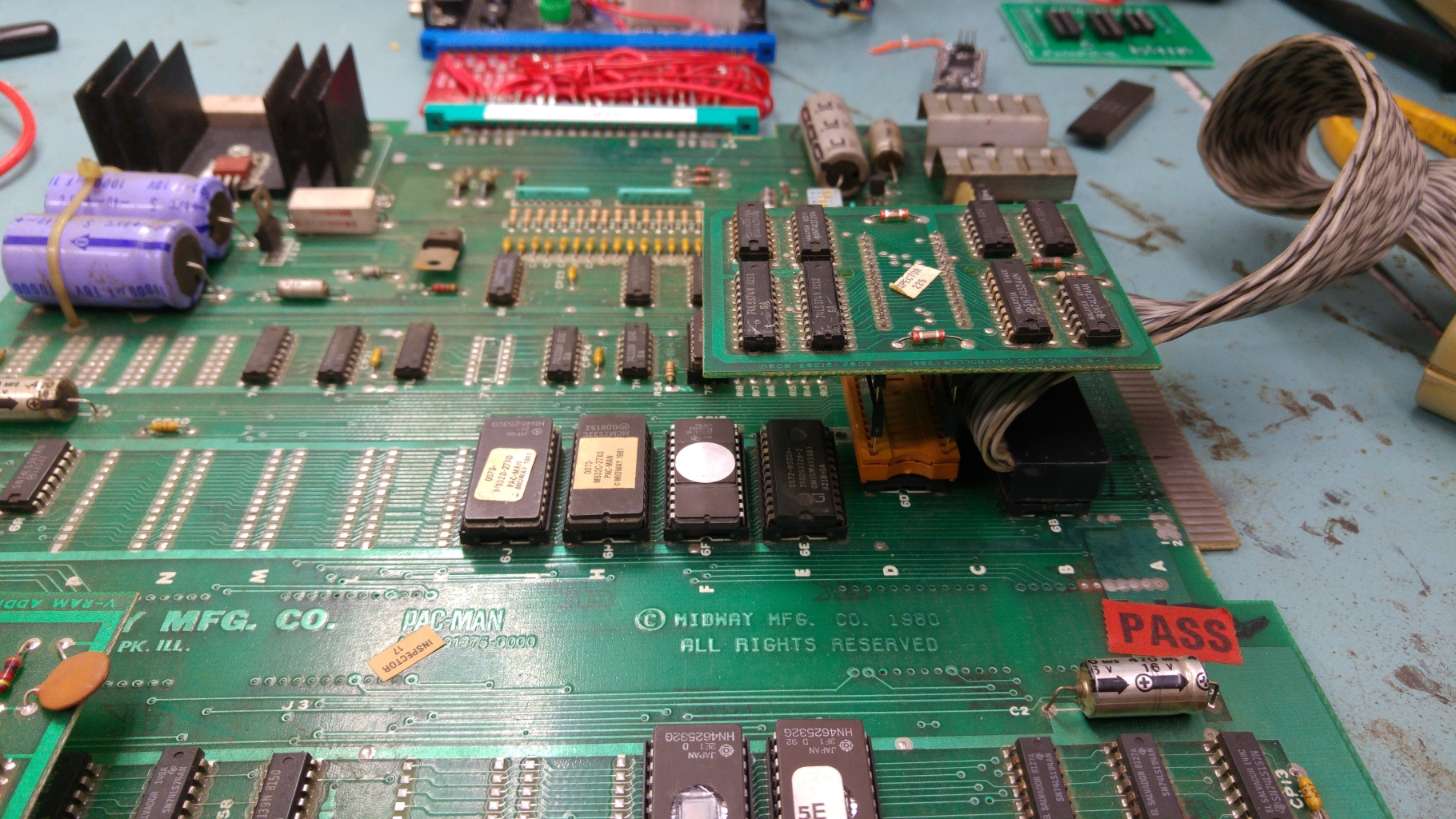
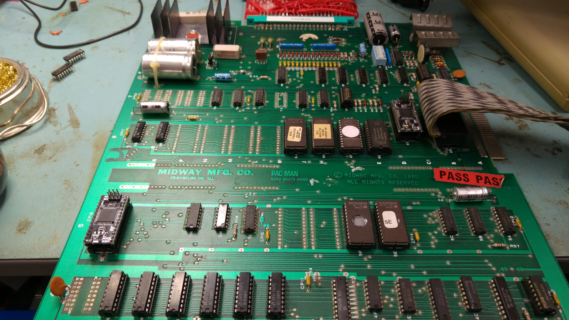
I recently asked on UKVAC if anyone had a Pac-Man PCB I could borrow in order to test the recreations of the two custom chips I made for the CPLD replacement device.
JonHughes replied and a few days later I had not one but two PCB’s to play around with.
One was pretty much stripped of parts but the other was complete and even had the TTL versions of the two customs.
I already have a JAMMA adapter for this that I made for my first Pac-Man repair so I was all ready to go.
Visual inspection revealed nothing to be concerned about so I went ahead and fired the game up.
I got nothing. The game was absolutely dead. I checked for activity on the CPU address and data bus but they were static.
Checking the clock pin also showed up no activity. Probing around the clock section suggested that the crystal had died so I went ahead and replaced it but this didn’t help.
There was a small build up of old flux around capacitor C4 so I went ahead and cleaned this up. The clock signal came back!
So now I had this my clock back and activity on the address and data bus lines but I still had a blank screen and it wasn’t making any noise. I also confirmed the board was not watchdogging.
Since the Z80 CPU is already socketed I decided to use the Fluke 9010 to check the ROMs/RAMs. Here is where a little problem came as the TTL custom replacement covers over the Z80 so I fitted a few header to the pins to raise it up enough to fit the Fluke pod.
With the Fluke connected I quickly verified the ROM’s and RAM’s were fine. It also verified that the connections between these chips and the Z80 were good.
Next step was to work backwards from the RGBS pins at the edge connector.
There was obviously no video output.
I found there was no activity coming out of the 74LS157 at 3A but some activity going in and to/from the connecting chips.
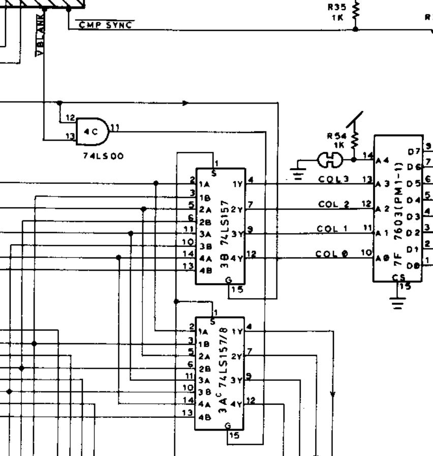
Checking the strobe pin (pin 15) of this chip I found the signal was stuck HIGH which basically means the chip was disabled.
Checking the 74LS00 at 4C showed I had activity on pin 12 but pin 13 was stuck HIGH. This being the /VBLANK it was clear that this was not correct.
The /VBLANK signal is given out by a 74LS74 chip at 5M.
Checking the signals on this chip I found the clock signal was stuck LOW.
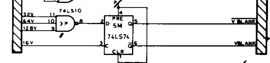
This clock signal is 16V signal that is generated by a couple of 74LS161 4 bit binary counters.
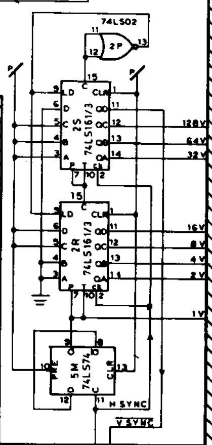
According to my logic probes there was no activity on pins 11 and 12 of the 74LS161 at 2R (the one that generates the 16V and 8V signals) but seeing as though this chip was already in a socket and it tested good in my chip tester I didnt believe what the probe was telling me so I fired up the scope to take a look at those pins.
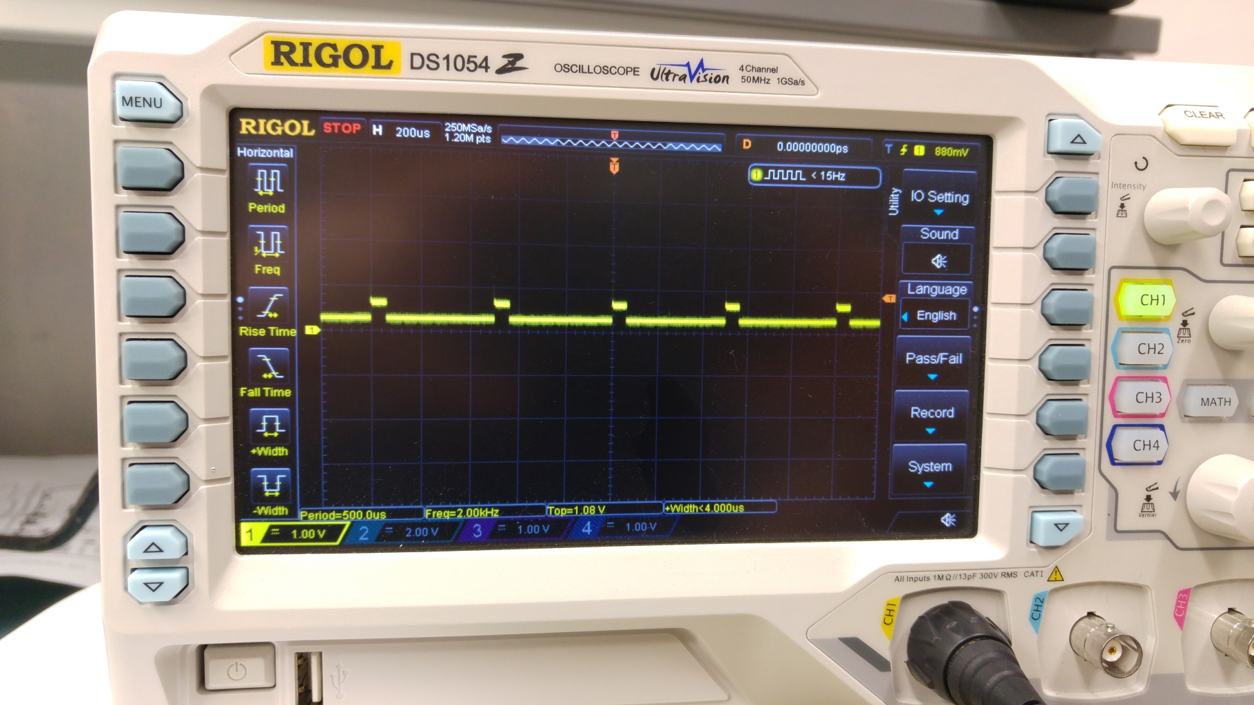
This is a good clear example of signal contention. You can see that the signal is trying to rise up but only getting to about half a volt. Knowing that the chip is actually good out of circuit confirms that there is another signal driving it low.
I found that pins 11 and 12 were shorted together.
I couldn’t see anything really wrong physically on the board where these two signals went so once again I opted to clean off the small bit of old flux I could see and once again this fixed my problem.
Although I’ve read about old flux causing issues I’ve never actually seen it myself until now so this has been a lesson learned for me.
Now I got this.
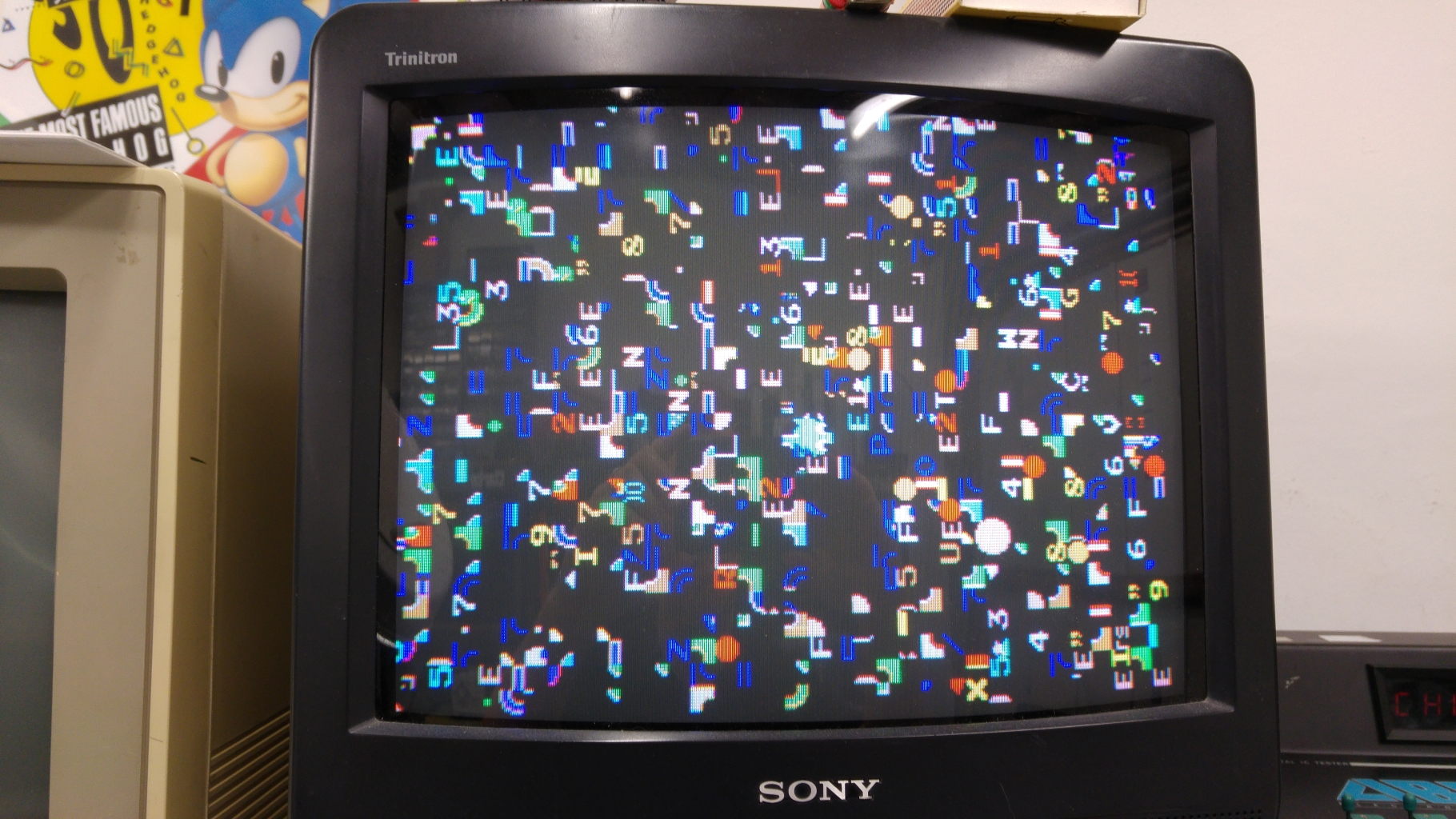
The game is actually running here but there is garbage on the screen. If I left it running all the sprites came on the screen and were complete.
Before moving on I decided to test out my CPLD implementation of the syncbus controller custom. This gave me the same output so was confident it was OK. Now I though I’d try out the VRAM addresser replacement too and I got this.
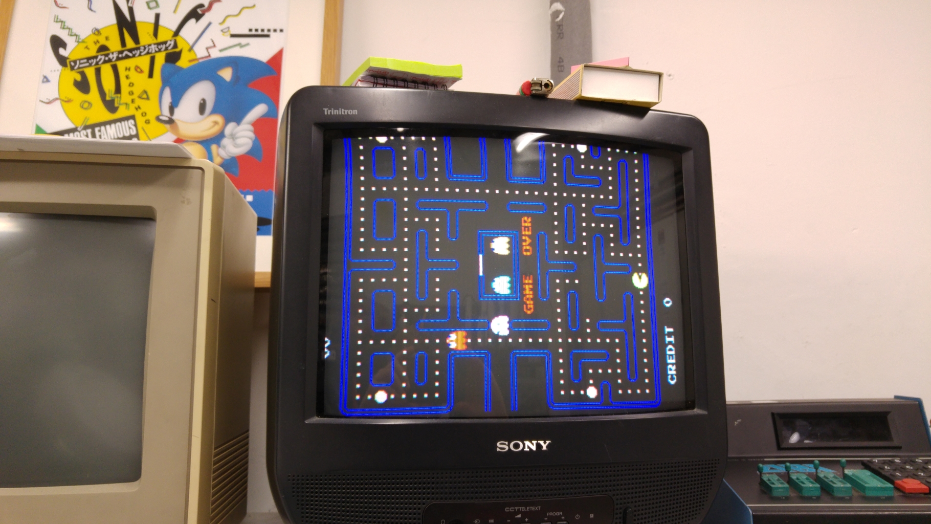
All fully working with sound too.
The actual cause of the earlier fault was created by me as I had bent 2 pins on the VRAM module during one of the many remove/replace cycles I had done. I since confirmed this works fine too.
That’s this board fully working and the two replacements confirmed working too.
Thanks to JonHughes for providing me with these boards.
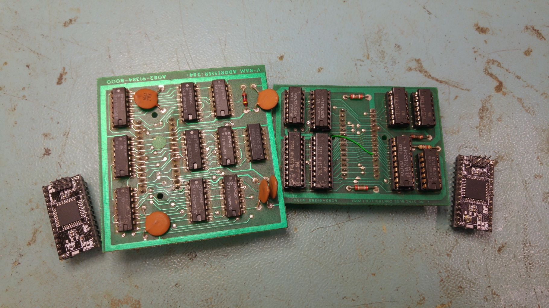
Today I have been able to test my recreations of the syncbus controller and VRAM addresser in ColinD’s 28 pin replacement.
Both files can now be downloaded.
Today we have a big PAL dumps update.
Our contributor ‘cpsystem3’ posted on Dumping Union a dump from a Global Champion Taito F3 cart.Device was an unlocked PALCE16V8H, dump has been tested as working on same part.According to him, it allows for larger audio samples/ bank support.Thanks to ‘cpsystem3′ for this contribution.
As for me, I dumped PALs from these PCBs:
-Explosive Breaker, a vertical shoot’em up from Kaneko (dumped only the socketed chips)
-Bang!, a lightgun game from Gaelco
-City Connection (bootleg)
I also dumped a secured GAL16V8 present on hardware of my defective EETools ChipMax2 EPROM programmer.All dumps have been tested (except for the ChipMax2 one) and working in a GAL16V8 targeting device (except one dump from City Connection which requires a GAL22V10)
Here is a picture showing a recently repaired Rastan PCB with the replaced chips highlighted in red.
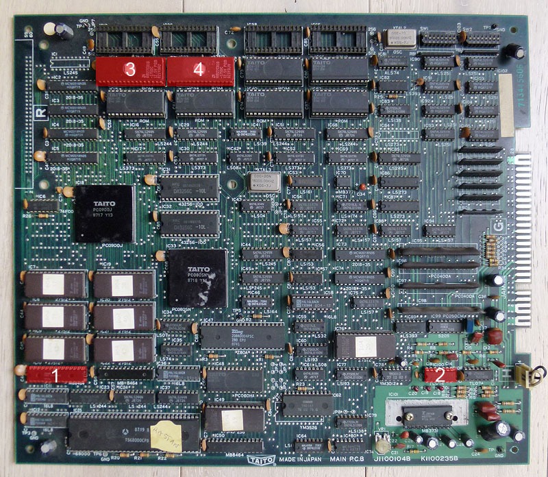
I will explain every step of the repair process here:
1) When powered up, the game was starting but was constantly rebooting after about 5 seconds. I checked the reset pin on the CPU but it was constantly high so that seemed not related to that. I checked the signals on the 2 CPU RAMs @ IC10 and IC22 (2x TMM2063 – 64kb) but nothing seemed suspicious. Anyway, piggybacking the one @ IC10 made the game not rebooting after 5 seconds but after a longer time. That was sufficient to let me think it may be faulty so I desoldered the RAM and it was tested bad on my programmer. Replacing it by a new one made the game working and not rebooting again and again. Good.
2) Well, the game was now playable but there was no FM sound (so no music at all), only voices were audible. Schematics are available online so I could see that the FM sound is generated by the YM2151 @ IC63 then it goes to an YM3012 DAC @ IC78 then it goes to a TL074 op amp @ IC100 to finally going to the MB3731 amplifier @ IC101. Outputs signals looked healthy at the outputs of the YM2151 and I had correct sound for the voices so the issue should be located before the mix between FM and voices signals, so before the amplifier: more probably within the DAC or the op amp. The TL074 is composed of 4 operational amplifiers:
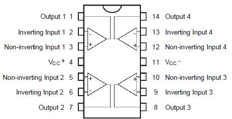
I noticed that every of the 4 output signals on the TL074 @ IC100 were looking weird with a negative voltage (between -1 and -2 V). There is another TL074 chip on the board that is related to the voices and every outputs showed a positive signal of approximately 2.5 V. That was suspicious so I desoldered the TL074 @ IC100 and replaced it by a new one and the FM sound was back ! (the signals on every 4 outputs were now showing a positive analogic signal of approximately 2.5 V).
3) and 4) Ok, so then the game was fully playable with perfect sound but there was some graphical glitches on a few items, as seen here in the attract mode:
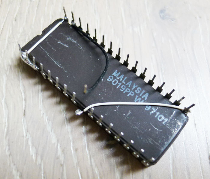
I have a previously repaired Rastan PCB that had one of its gfx mask roms replaced by an hacked 27C010 EPROM so, due to the nature of the problem here (glitches on only a few particular items), I suspected one or multiple MASK ROMs to be faulty. I started replacing these ROMs with the ones from my working Rastan PCB and got the gfx working perfectly after replacing B04-07 @ IC14 and B07-08 @ IC27. As noticed in my previous Rastan repair log, the gfx ROMs on this board are 128kb fitted into 28 pins chips. Finding blank chips with these exact specs is hard nowadays so I used 128kb 32 pins 27C010/27C1001 EPROMs as replacement (I could use a 27C1000/27C301 EPROM to make the modification even easier but I didn’t have one remaining then). To fit them on the 28 pins sockets present on the Rastan board, you have to make the following modifications on every EPROM:
If you use a 27C301 or 27C1000 non-JEDEC EPROM (simplest way):
If you use a 27C010 or 27C1001 JEDEC EPROM:
I did these connections on the underside of the chip. Here is how it looks on my 27C010:
And this is how it looks after the 2 chips plugged in:
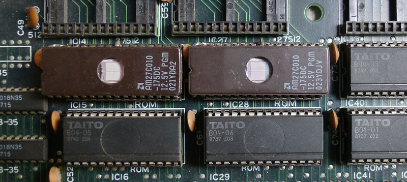
Now the gfx are fully restored, as well as the rest: