NAOMI Netbooting

 General  Comments Off on NAOMI Netbooting
Jul 232011
 

Was unsure whether or not to post this but here it is anyway but without links to any of the utilities needed. I actually own a fair amount of GD-ROM games and netbooting gives me a more convenient way of loading my games now my GD drive is dead.

As most owners of a Net DIMM will know, it is possible to load code from a PC via ethernet.
To start with there are some jumpers to change on the DIMM board to set it to network mode.
My net DIMM had version 3.03 firmware which is fine for netbooting but as my ultimate goal was to build my own compact flash booting device I need the latest firmware, 4.01.

My first problem came with the DIMM boards I have. They were not recognised by my NAOMI.
My BIOS was 21577D which is too old for network support.
A newer BIOS was needed so I burned a new 27c160 EPROM with the latest available export bios.
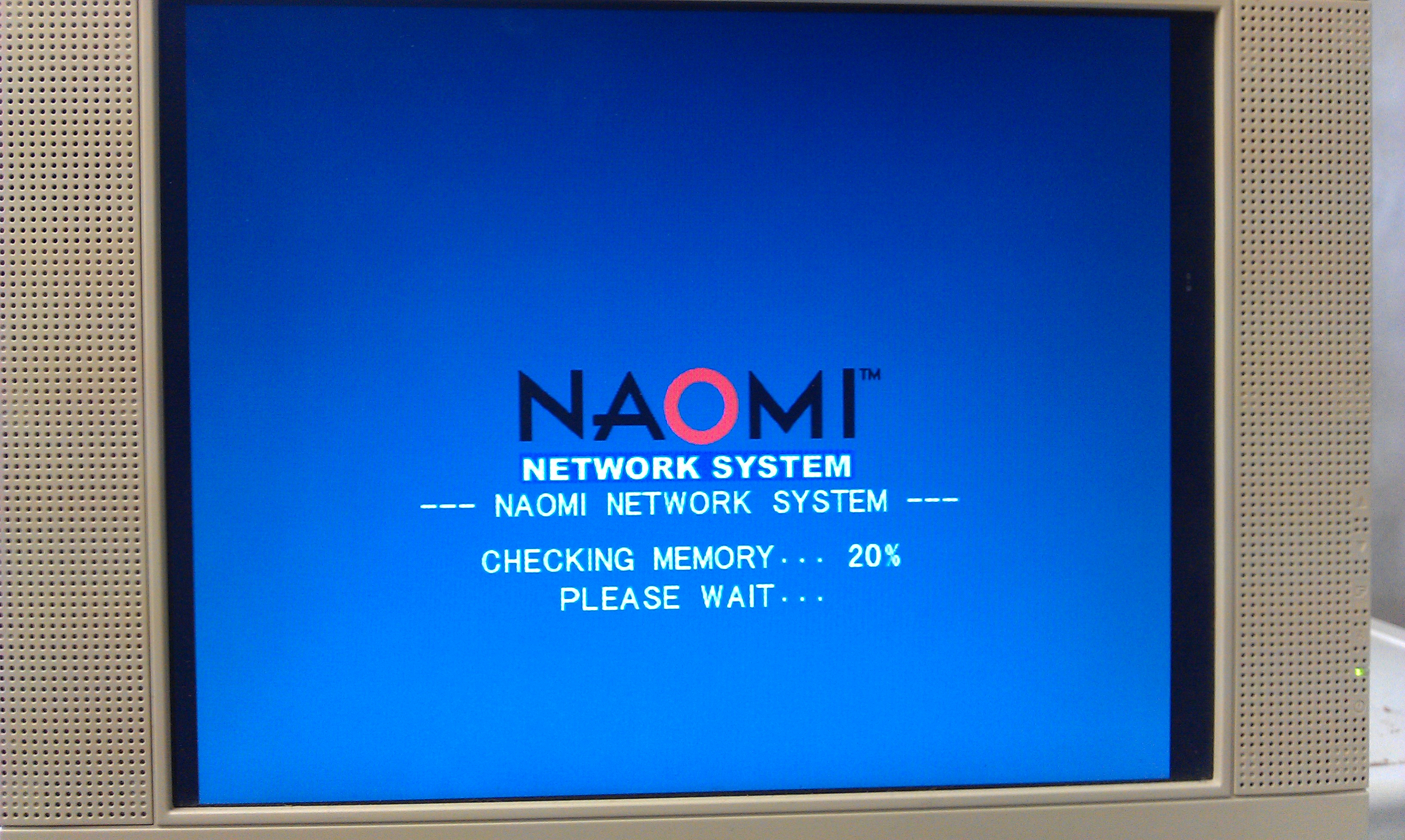
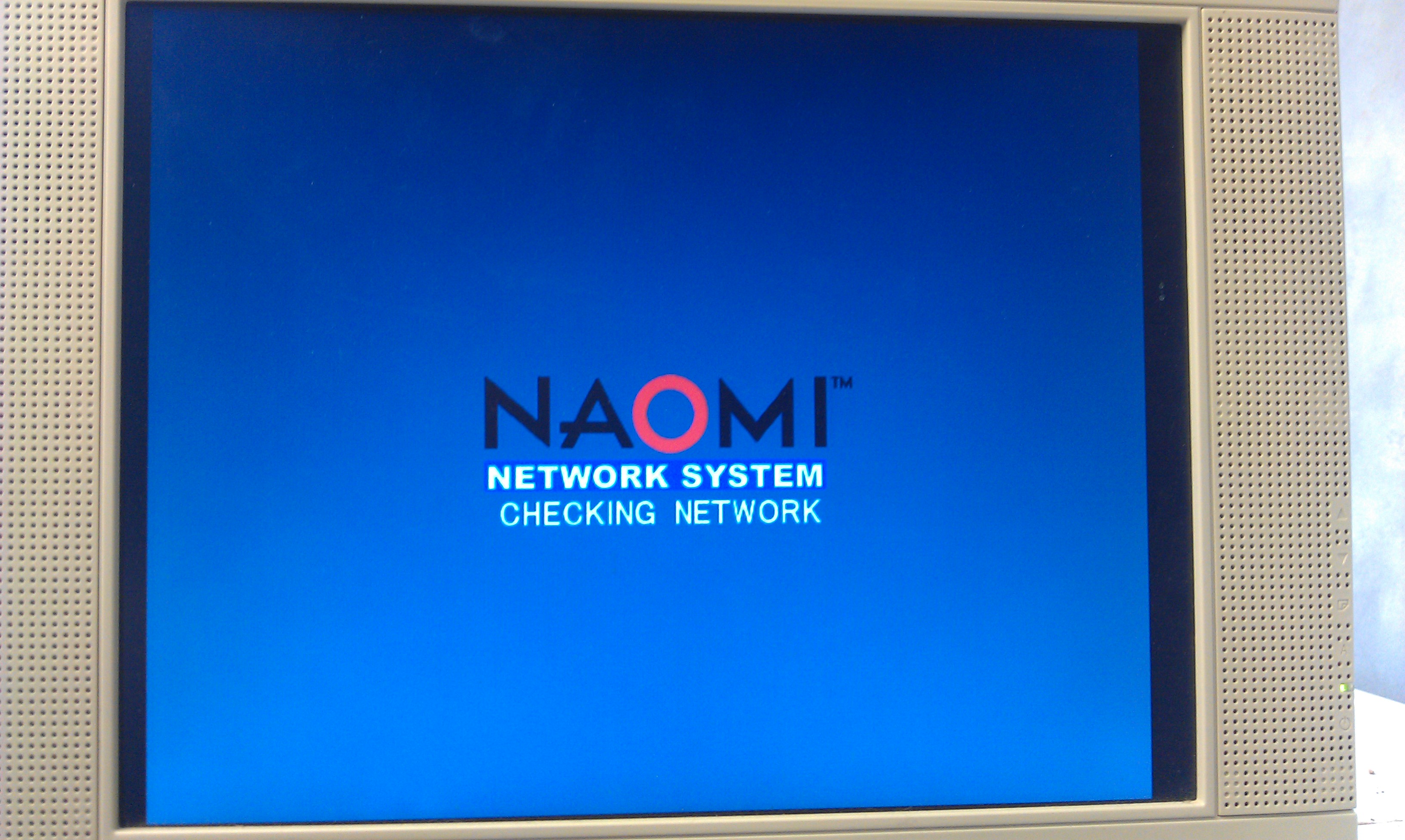
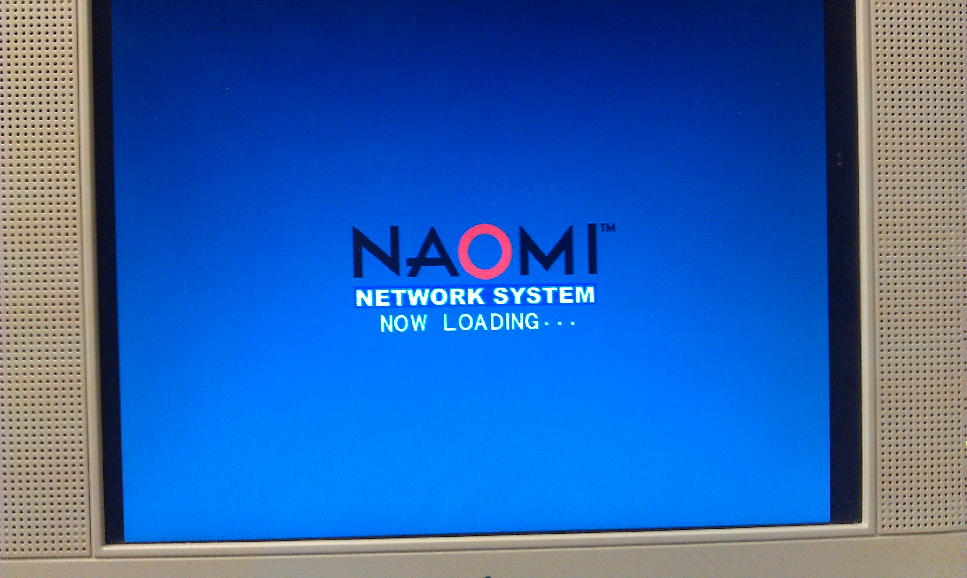
This let me access the DIMM module in the test menu.

In the test menu you can setup the network settings.
The device must be set to ETHER
The network IP and subnet need to be correctly set too.

My second problem came with my ethernet cable.
As I wasn’t using a router or similar, I needed a crossover cable and the one I very quickly knocked together ended up being useless.
The second one I made up worked a treat and I could then PING the system.

First job was to update that firmware.
There are 2 tools available for uploading to the DIMM.
The first one is the official SEGA one called “transfergame.exe”
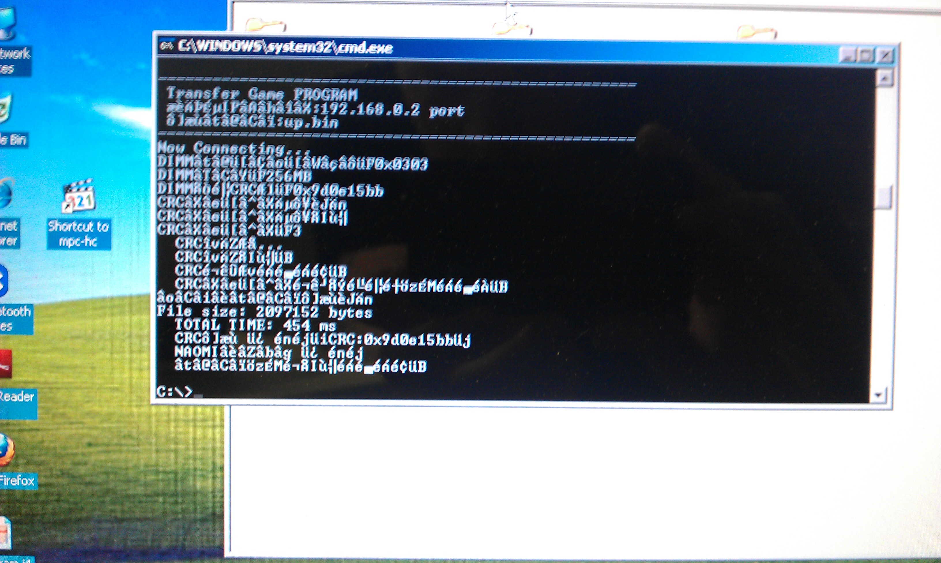
I had no luck at all with this program, probably because I didnt know what security net pic to use.
I had burned several different replacement pics but none seemed to work correctly.
I gave up with the official software and downloaded the very excellent triforcetools python script.
To use this you need to download all the associated Python files.
This script runs pretty much the same way as transfergame.exe in terms of usage but sets the DES key to zero so any net pic can be used.
As it happens I didnt get much further with this at first as it kept giving me a Error 31.
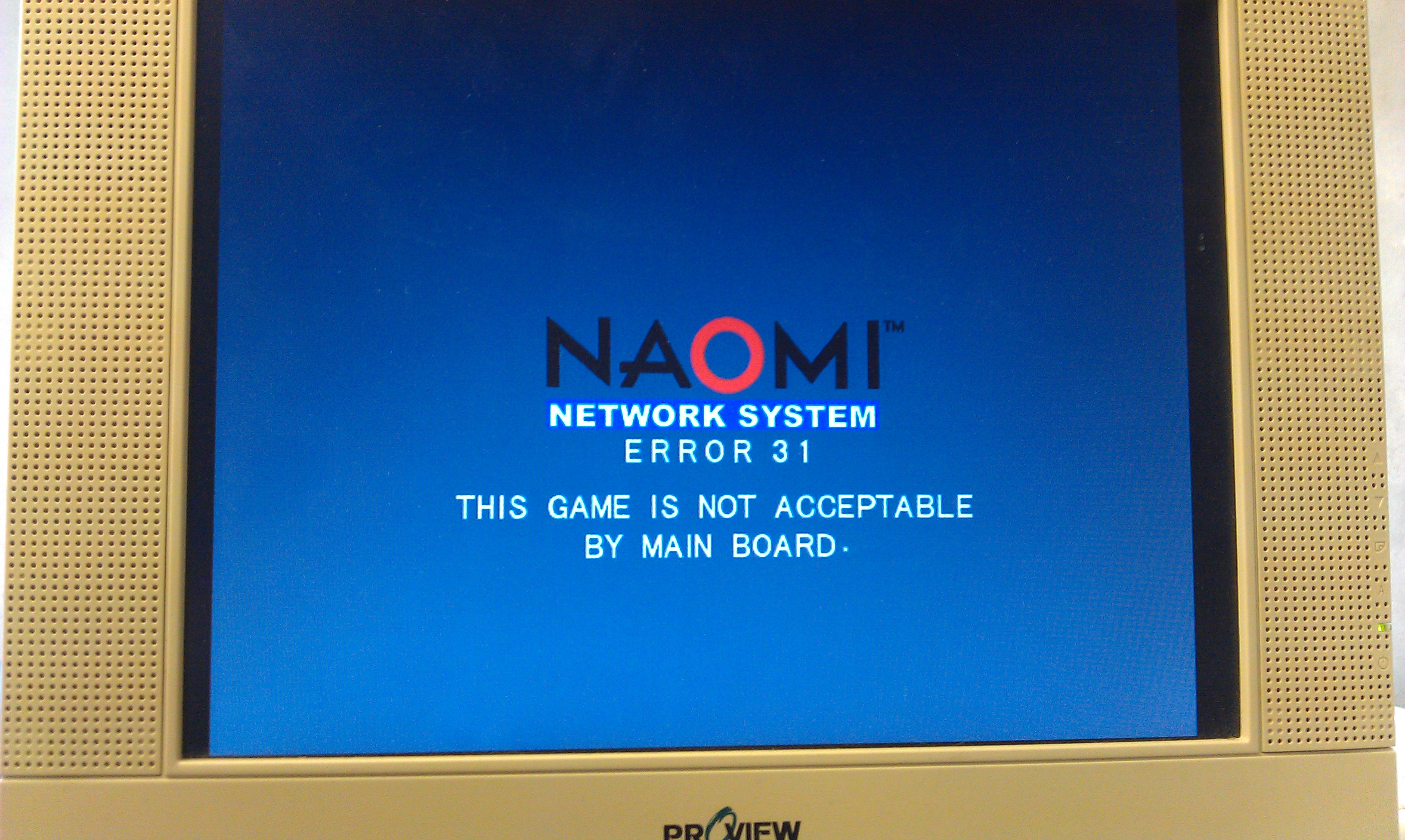
With no ideas I gave up for a day.

Whilst doing a lot of searching around the internet I found a modified version of the python script which claimed to remove the need for any security pic to be inserted at all, and it works a treat too.

Using this I managed to upload the new firmware and update the DIMM to v4.02 (this version lets a user use any CF card and not just an official SEGA one).

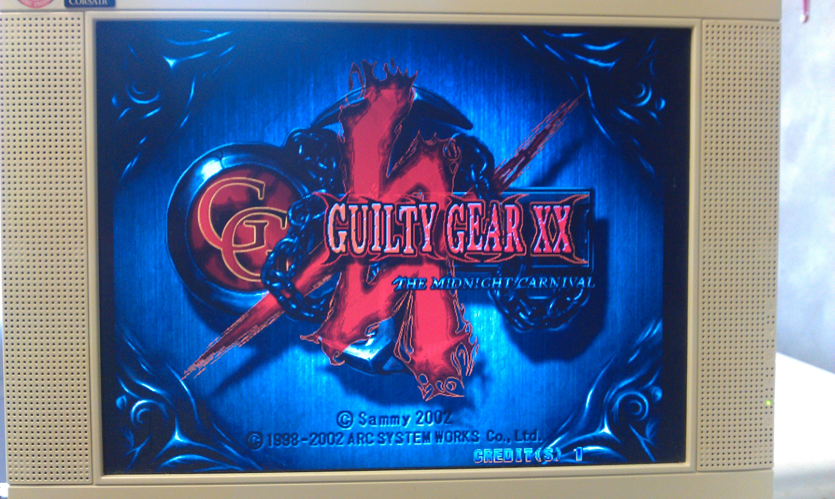
I also managed to boot Guilty Gear XX too. All works fine. Now I have this working I am starting to think I dont need to build the CF adapter but since I have all the parts needed I might as well do it.
SEGA ST-V repair log #1

 PCB Repair Logs, Repair Logs  Comments Off on SEGA ST-V repair log #1
Apr 282011
 

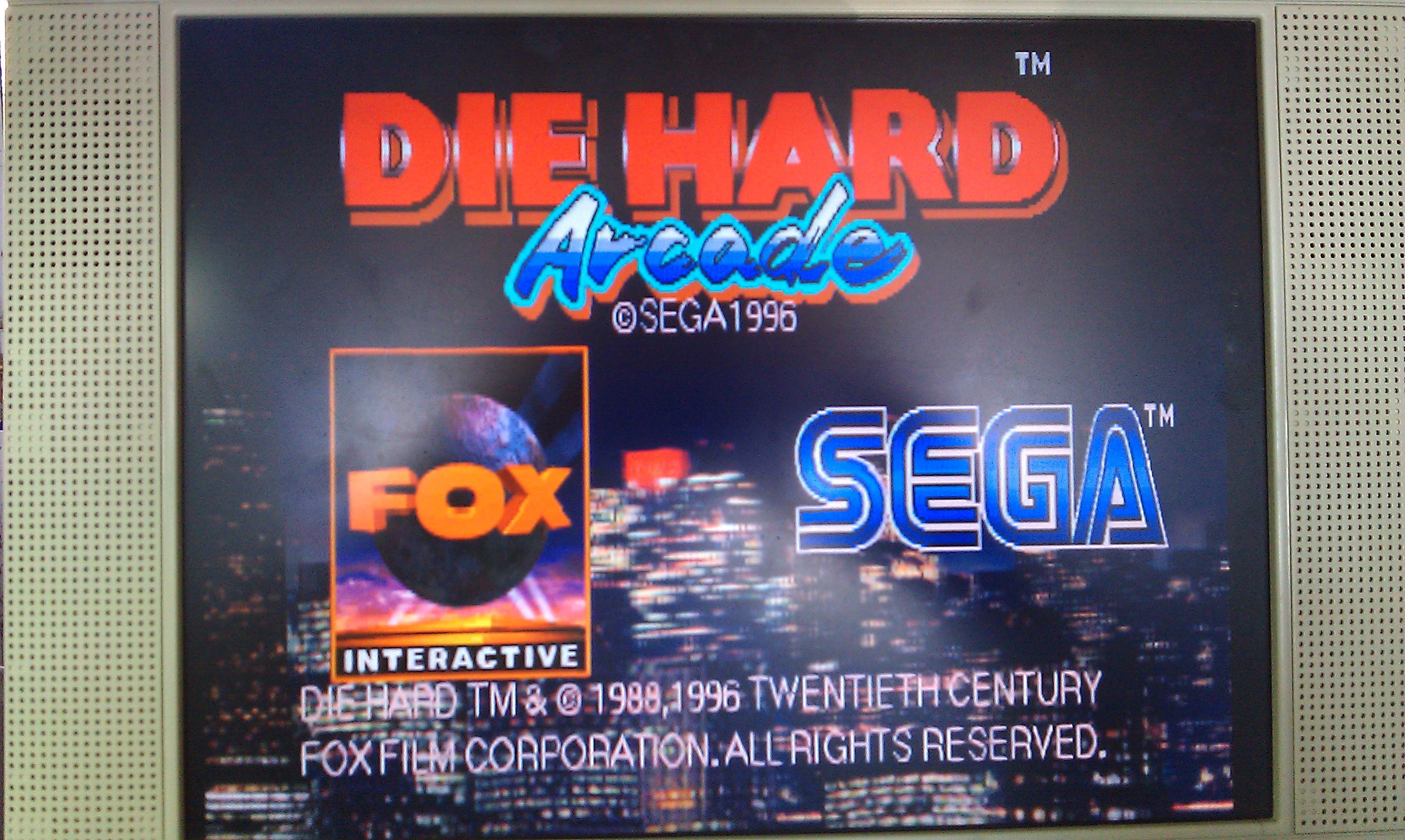
First repair from the lot I recently got. Sega STV motherboard with Die Hard game.
When booted up with no game cartridge the board passed all it ROM and RAM tests. With a cartridge inserted the board crashes after the copyright screens. All the cartridge tests also came up as being good.
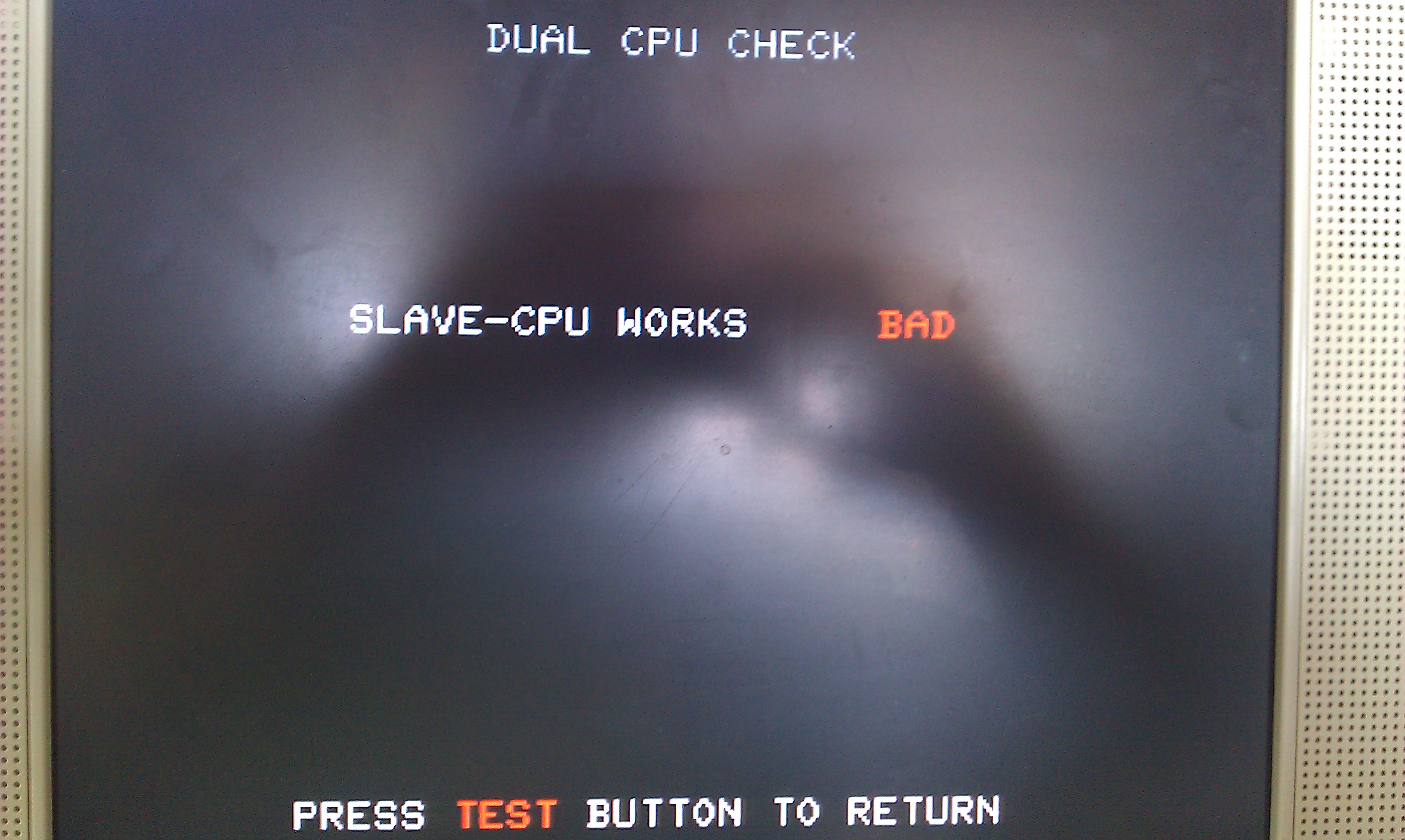
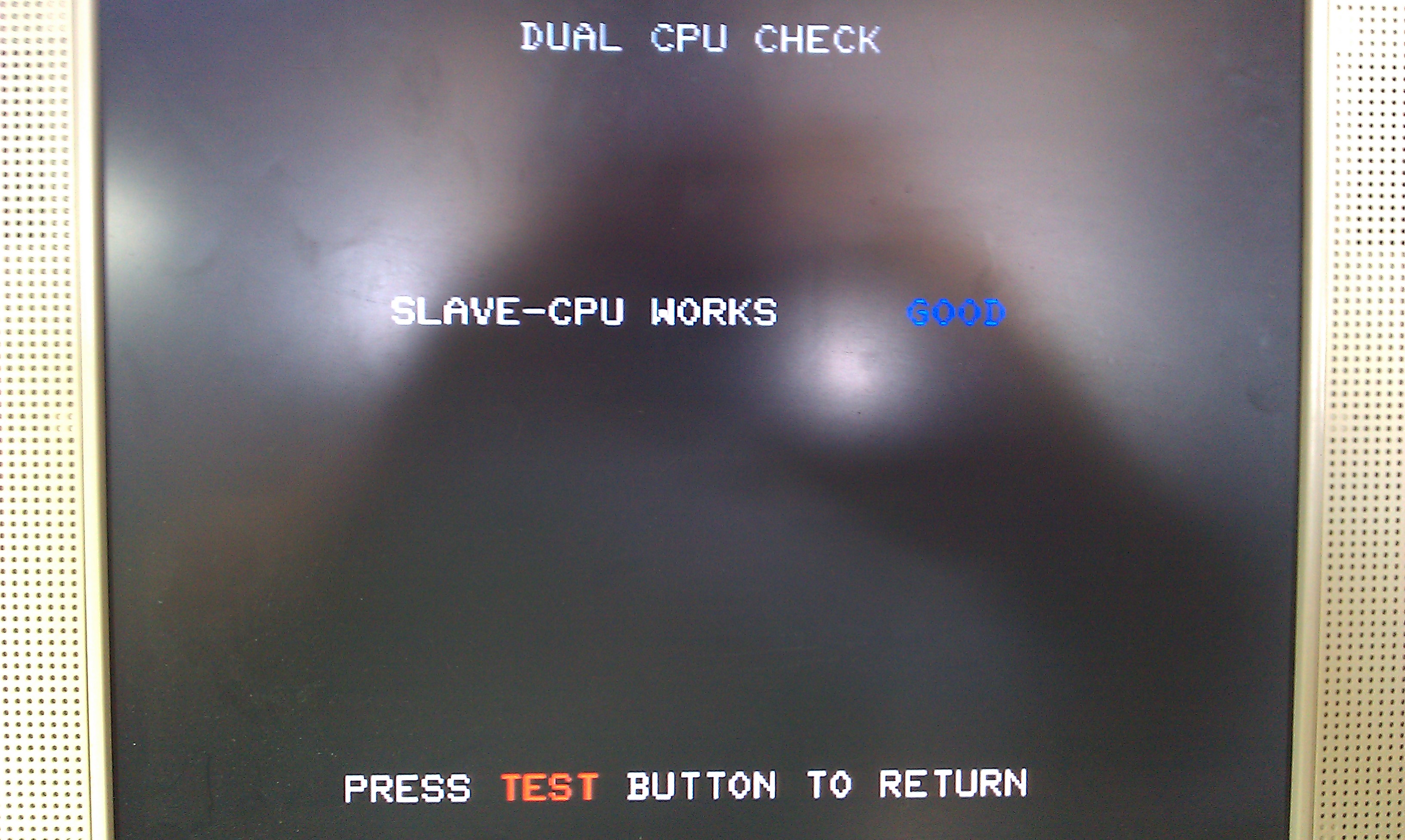
There is a developers test menu that is accessed by holding the TEST button down on power up of the board, this gives you access to a whole host of extra tests, one of them being a Sub-CPU test. Running this test flagged it up as being BAD and the board locks up.

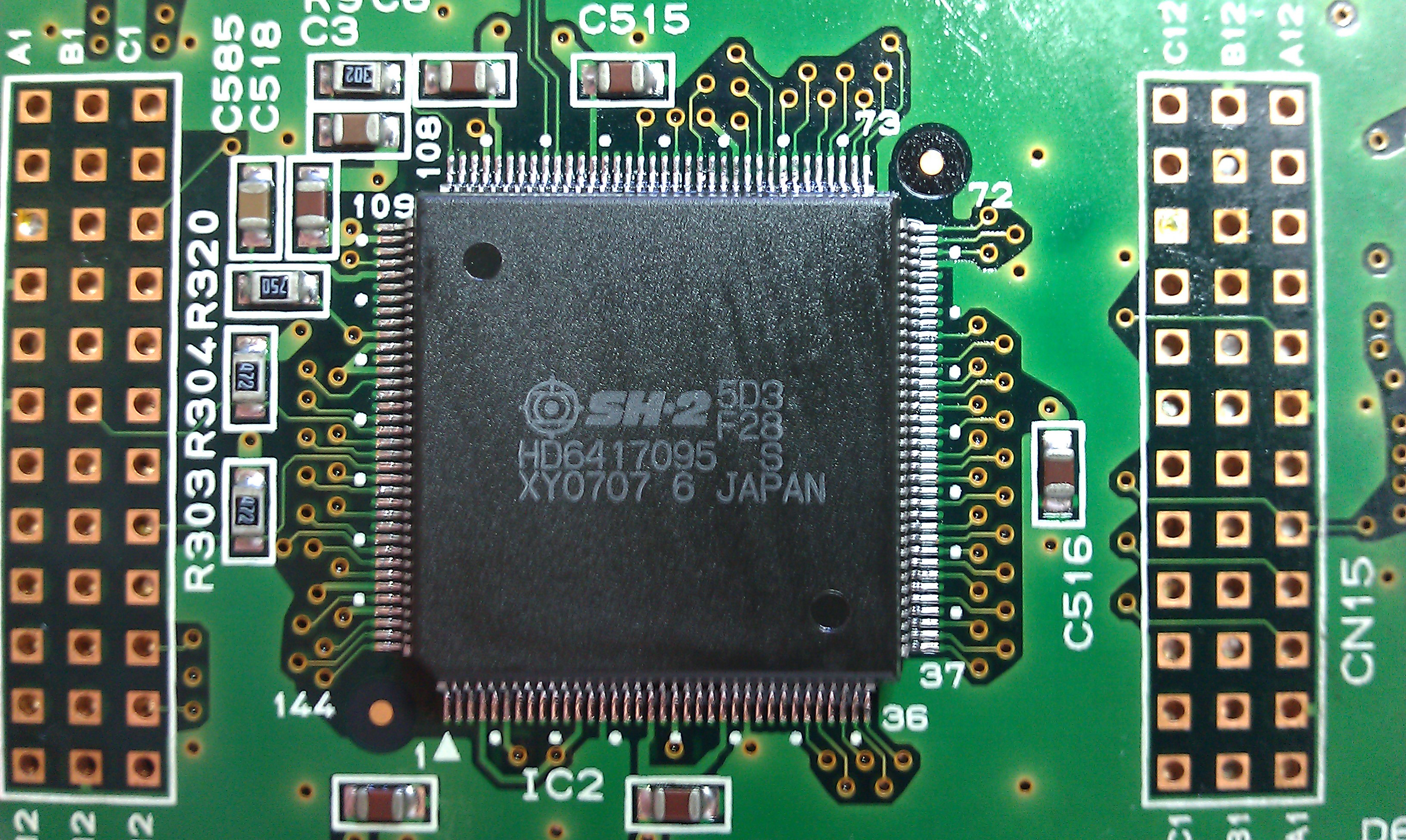
If I pushed down on IC2 (this is the Sub-CPU, an SH2) the board would pass its test.

This fault seems to be very common on STV motherboards and is easily fixed by reflowing solder on all the pins on the SH2 processors. I did both of them for good measure and the board now passes all its tests and the game boots up.


Not played this game before and its actually quite fun, like a mashup of Virtua Cop, Virtua Fighter and a little bit of Shenmue thrown in for good measure, it would make sense as the STV hardware is based on the Sega Saturn (or vice versa?).

SEGA Master System repair log #1

 Console Repair Logs, Repair Logs  Comments Off on SEGA Master System repair log #1
Mar 212011
 

Got a couple of Master Systems for repair.
This one was completely dead on power up.
First thing to check with a dead unit is voltages. The master system has a voltage regulator which in this case was fine. Second thing to check is the clock signal. The Z80 has its clock signal at pin 6. This was quiet. Traced it back to the large custom chip. Looking at the schematics the custom chip takes the clock signal from the crystal and then outputs a clock to the Z80. I checked pin 30 of the custom and this was also quiet.
On this model the crystal is located under a metal housing that is soldered underneath. I removed this cover and checked the output from the 54Mhz crystal. Nothing. Replaced this and the unit boots again.

Pitfall II repair log #1

 PCB Repair Logs, Repair Logs  Comments Off on Pitfall II repair log #1
Jul 252010
 

I wired up the non jamma board I recently got, its a SEGA board marked up as Pitfall II but at some point the ROMs had been swapped out for Wonderboy ones. I already have a Wonderboy board and prefer them to be original so I burned a new set of Pitfall unencrypted roms and swapped them over.
I noticed the the game also had a fault where the left side of the screen was repeated on the right side. After a little tracing out I found a 74LS283 with a floating pin, I swapped this for a spare and fault fixed.
Not a fan of this game, will probably sell it.

Golden Axe repair log #1

 PCB Repair Logs, Repair Logs  Comments Off on Golden Axe repair log #1
Jul 242010
 

I have decided to take a look at the Golden Axe problem today.
The problems with it are:
1. None of the inputs register
2. There is no sound

Normally faulty inputs are easy but not with the System 16 board. The inputs are controlled and isolated by 8 NEC2501 chips. I couldnt find a single bit of info on these chips but as luck would have it when I removed the chip from the board there is an alternative printed on silkscreen of TLP521-4. The datasheet for these is readily available and its description is a photo transistor. I wasnt prepared to believe that all 8 of these chips had gone so I traced the pinout back to the edge connector. It turns out that pin 4 on the solder side of the edge connector NEEDS to be connected to its own +5v as this supplies the voltage to the photo transistors and in my haste to get an adapter up and running I never wired all the points in. Lesson learnt. All inputs have now been tested working.
Next job, sound. I have dumped the 2 ROMs associated with the sound and checked them against MAME, both are good.
NOTE: The SEGA branded MPR- maskroms can be read as a 27c301 with a slight wiring mod.

There is a Z80 on the board which is the processor for the sound, this was dead. Replaced the processor and full sound is there.

Very happy to have this one up and running.