Juno First repair log #2

 PCB Repair Logs, Repair Logs  Comments Off on Juno First repair log #2
Jun 152014
 

So here is the second repair log.
Pretty simple this one but I never took any pictures of the actual fault so Ive taken a snapshot of the event in MAME to show it.

The game plays as normal but when the blue ball enemies spawn into the game the froze up on screen and did nothing as circled in red in the picture below.
juno2

On my visual inspection I noticed a 1K pull up resistor array next to the bank of 4116 RAM chips what cracked in half.
juno2-1

Replacing this fixed the fault.

I did initially think there was another fault as the ship movement in attract mode seemed a bit strange but after checking in MAME this is a characteristic of the non Gottlieb version. In the Gottlieb version this behavior is not present.

Jun 062014
 

This is hopefully one of five Juno First repair logs.
Thanks (I think) to muddymusic I have a stack of these needing repaired. There are two originals and three bootlegs altogether and decided to make a start on the originals first.

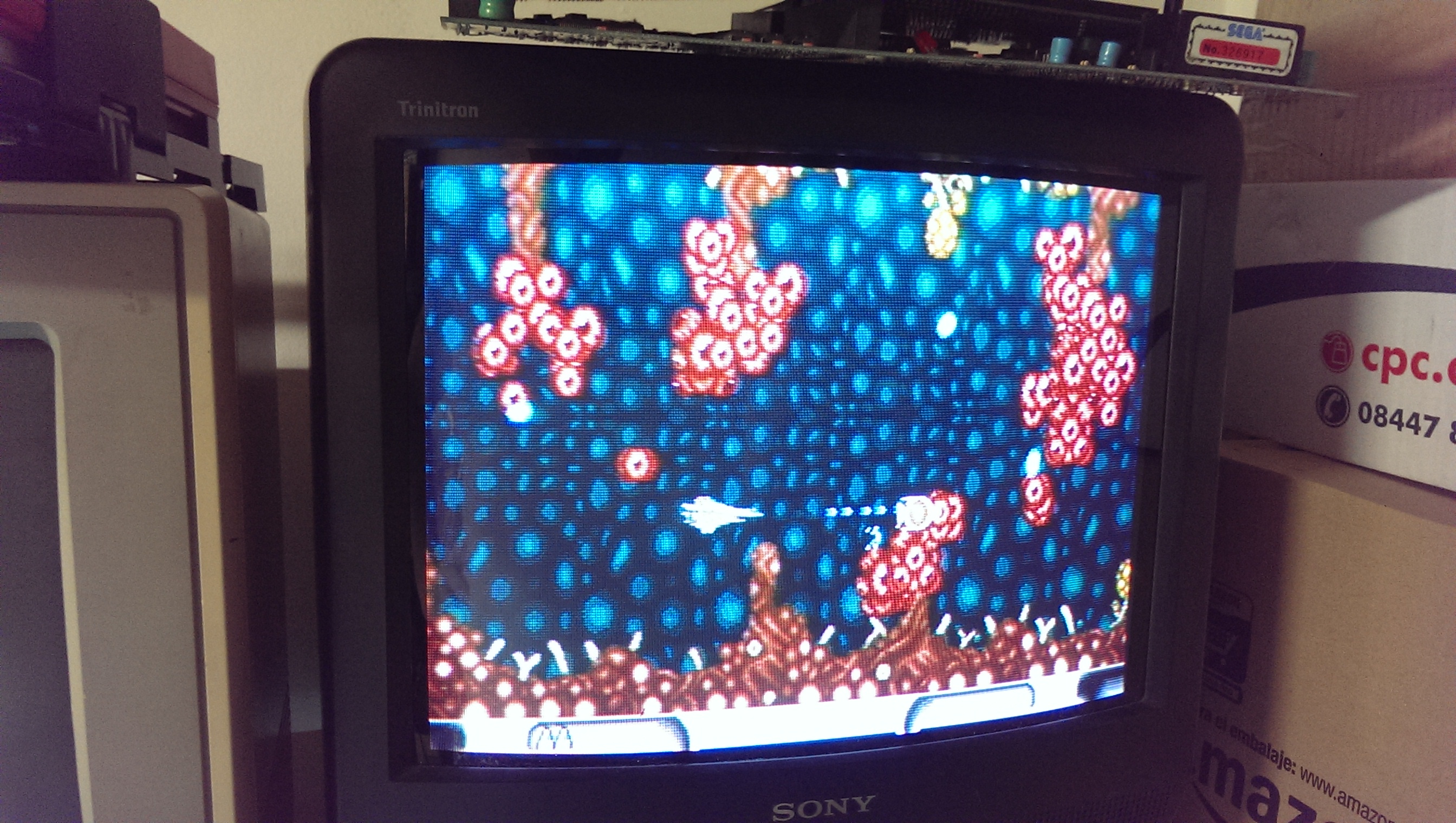
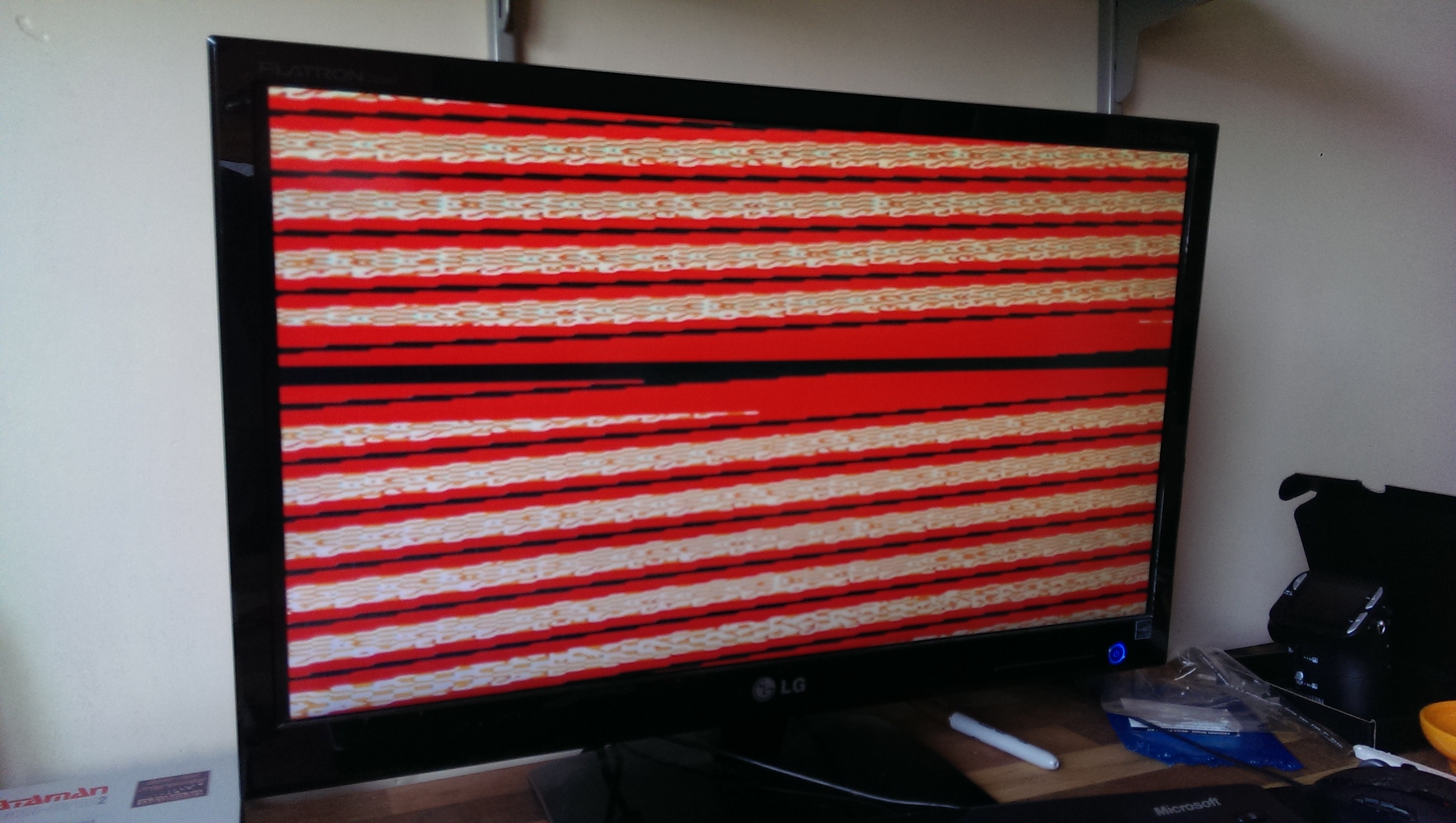
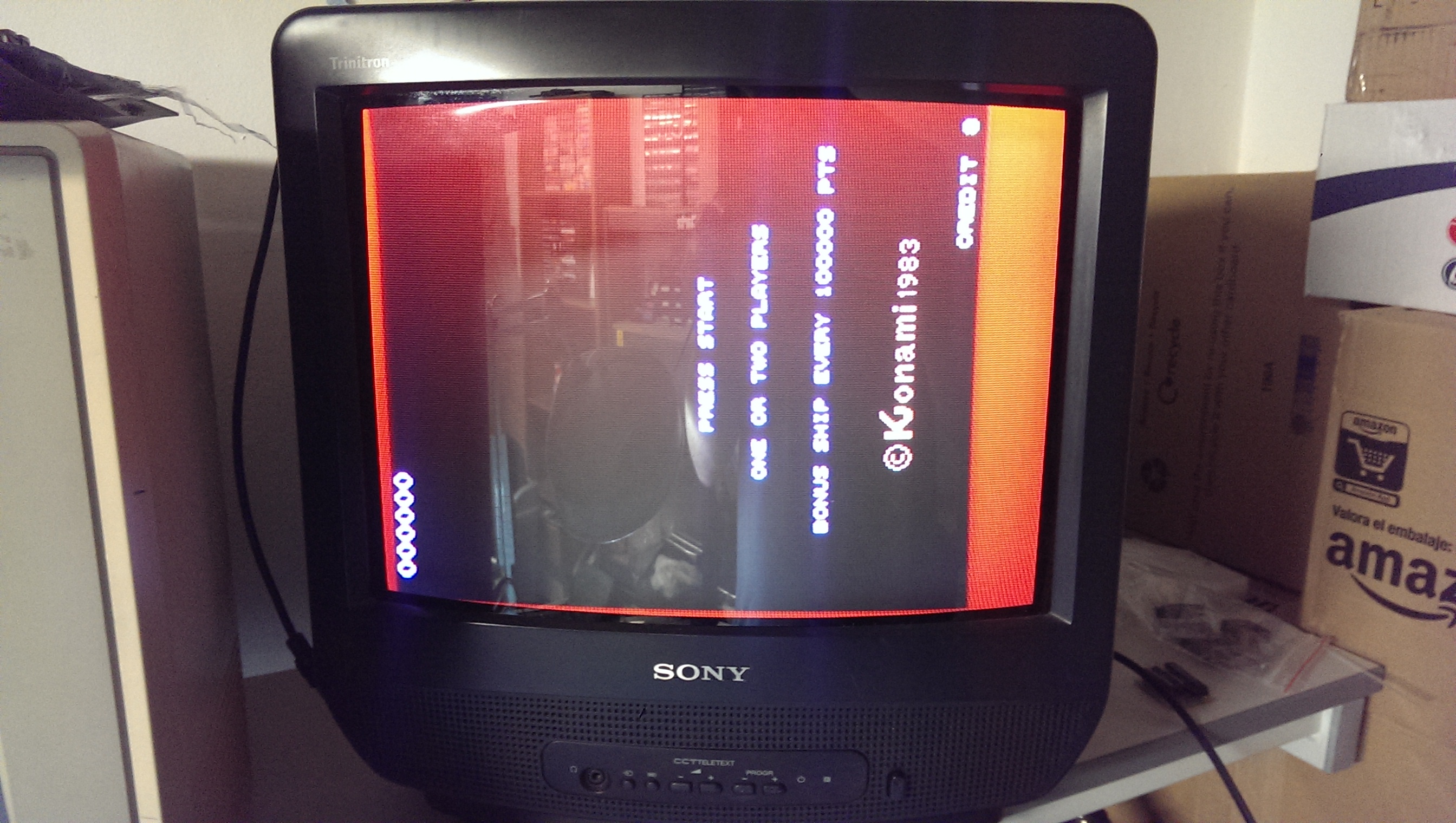
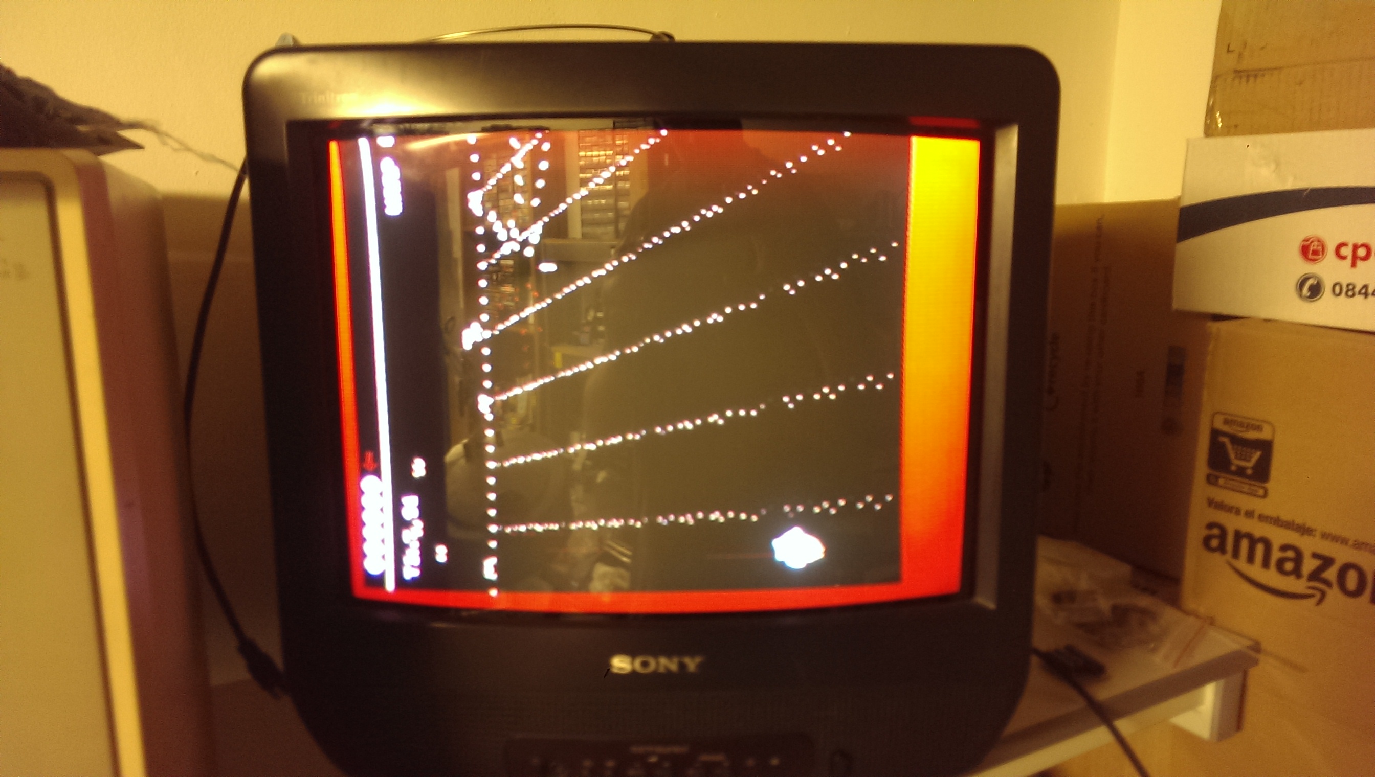
This one booted to an unsynced red picture.

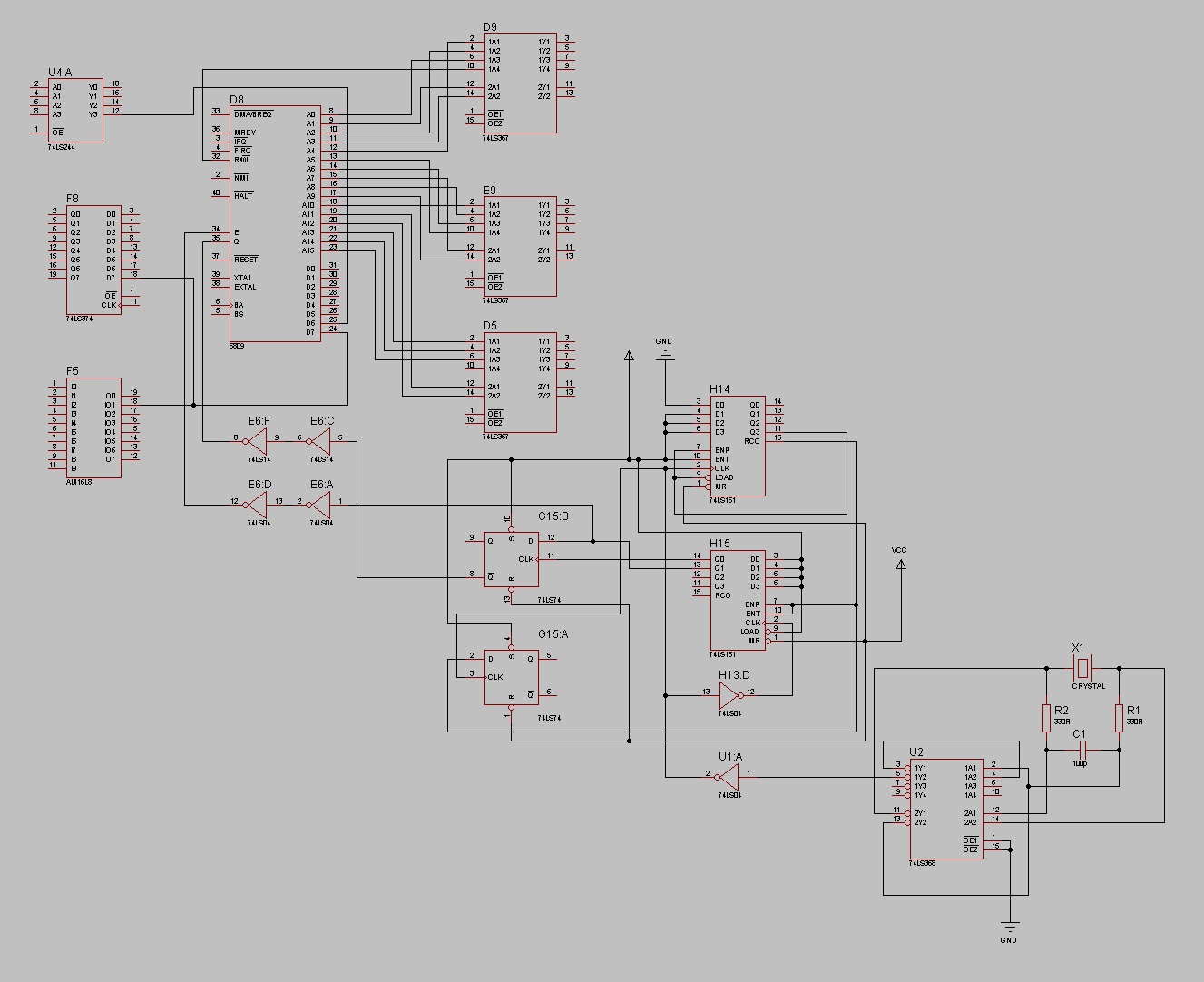
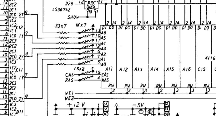
Looking at the schematics I could see that the sync is generated by custom chip 082 at location EF13 on the bottom PCB.
Swapping this chip with the one from the other board set brought the sync back. That’s bad news for original board set #2.

So now I just had a red screen with nothing going on.
It was at this point that I learned this hardware uses a custom 6809 CPU known as Konami-1. I was originally going to try and borrow a 6809 pod for the Fluke but that put a swift end it that idea.
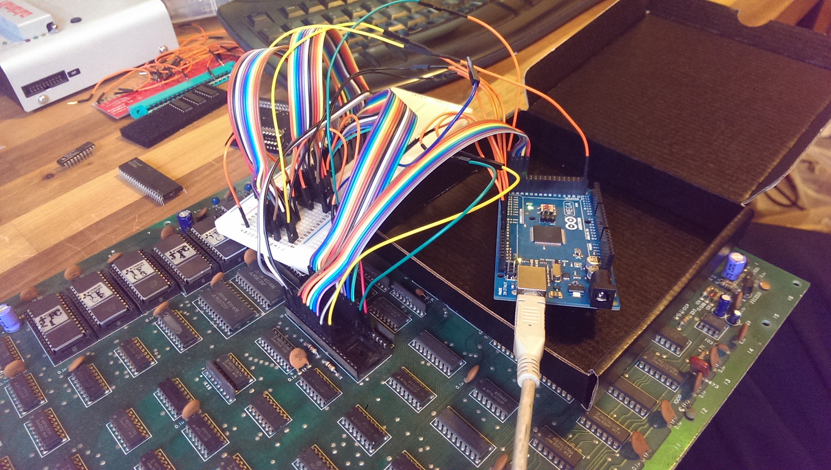
Now’s the perfect time to use my beloved Arduino again.
By hooking it up to the address, data, RW, BA and BS lines I wrote a program that would read the program ROM’s back and display the data as well as a bitsum for the ROM.
It worked really well and found my second issue.

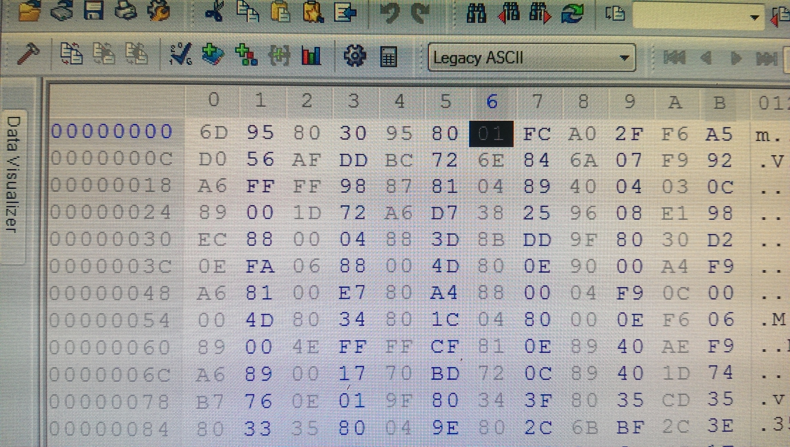
This is the original HEX file

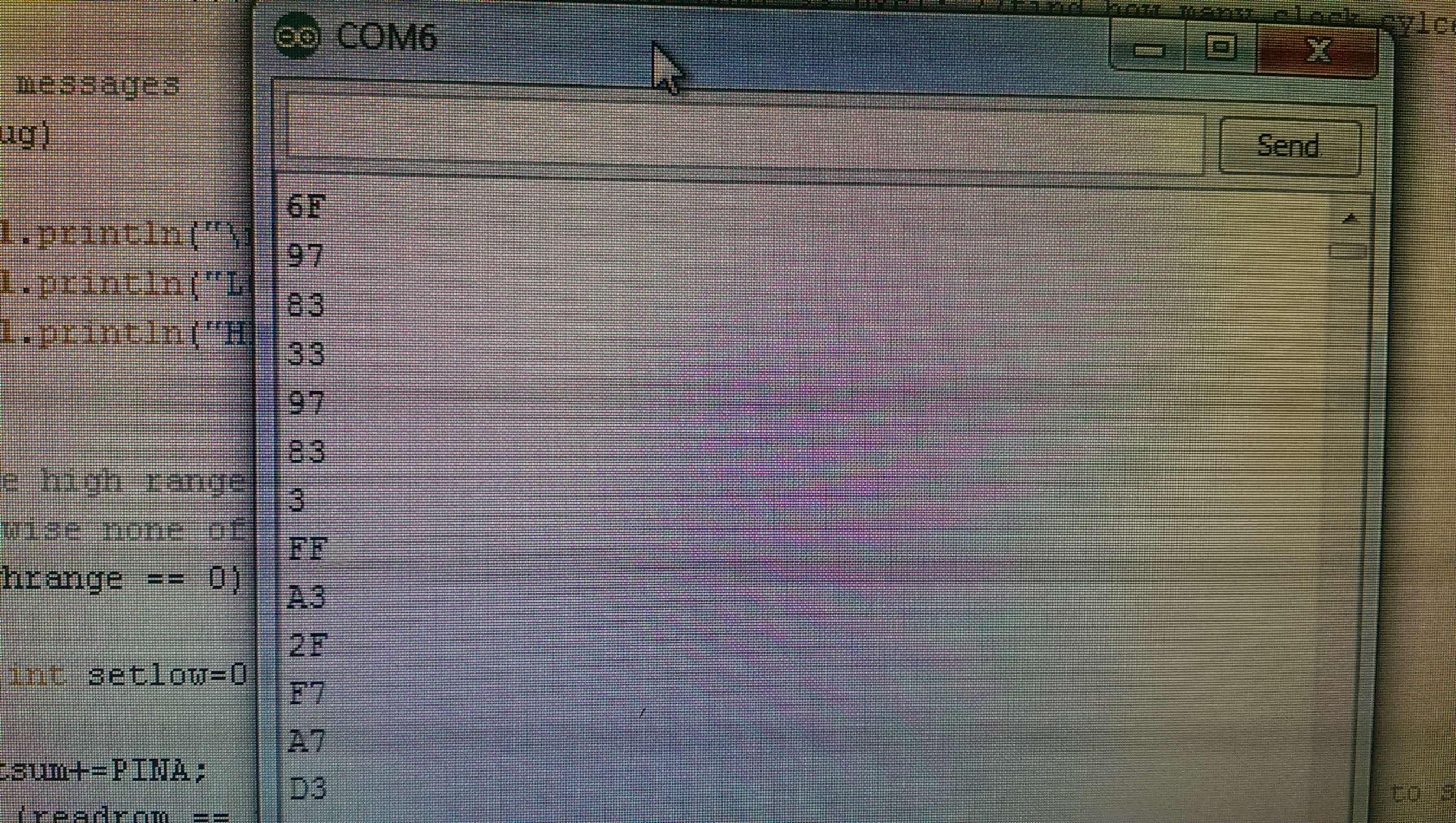
and here is what I was actually reading on the board

You can see that bits 0 and 1 are always on.

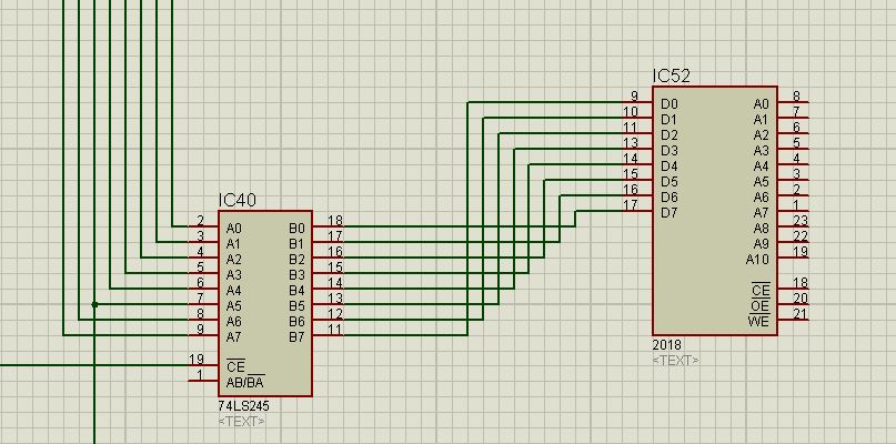
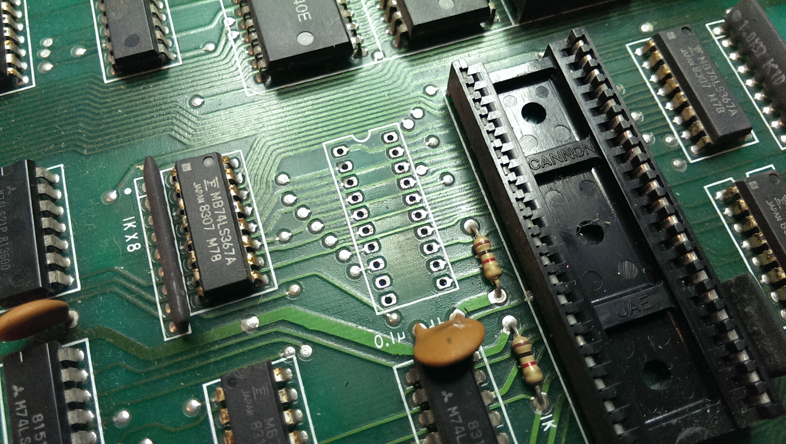
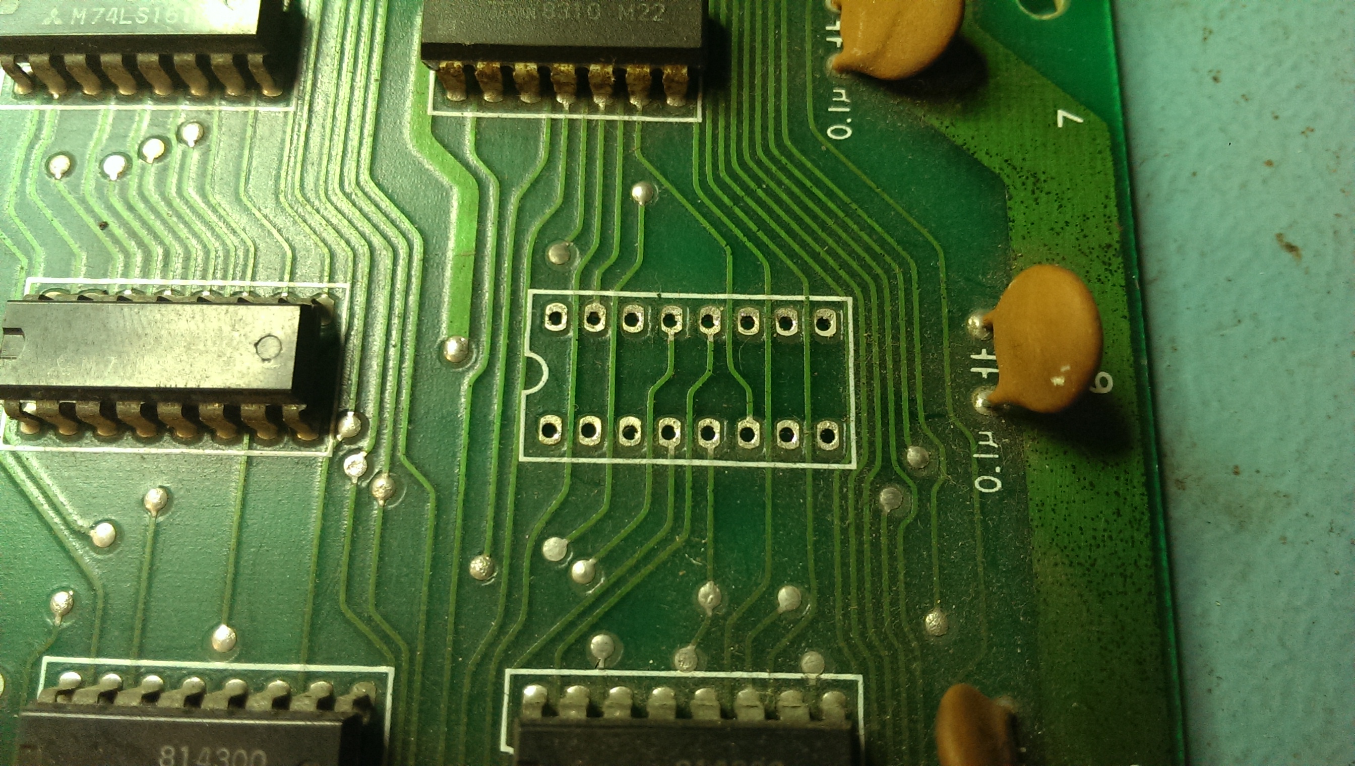
So the 74LS245 at location D7 on the lower PCB had a two stuck pins on D0 and D1.

Replacing this enabled me to read all the program ROM’s correctly.
I had at this point wanted to be able to test RAM too but due to the timings required and not knowing how those custom chips worked I left it alone.

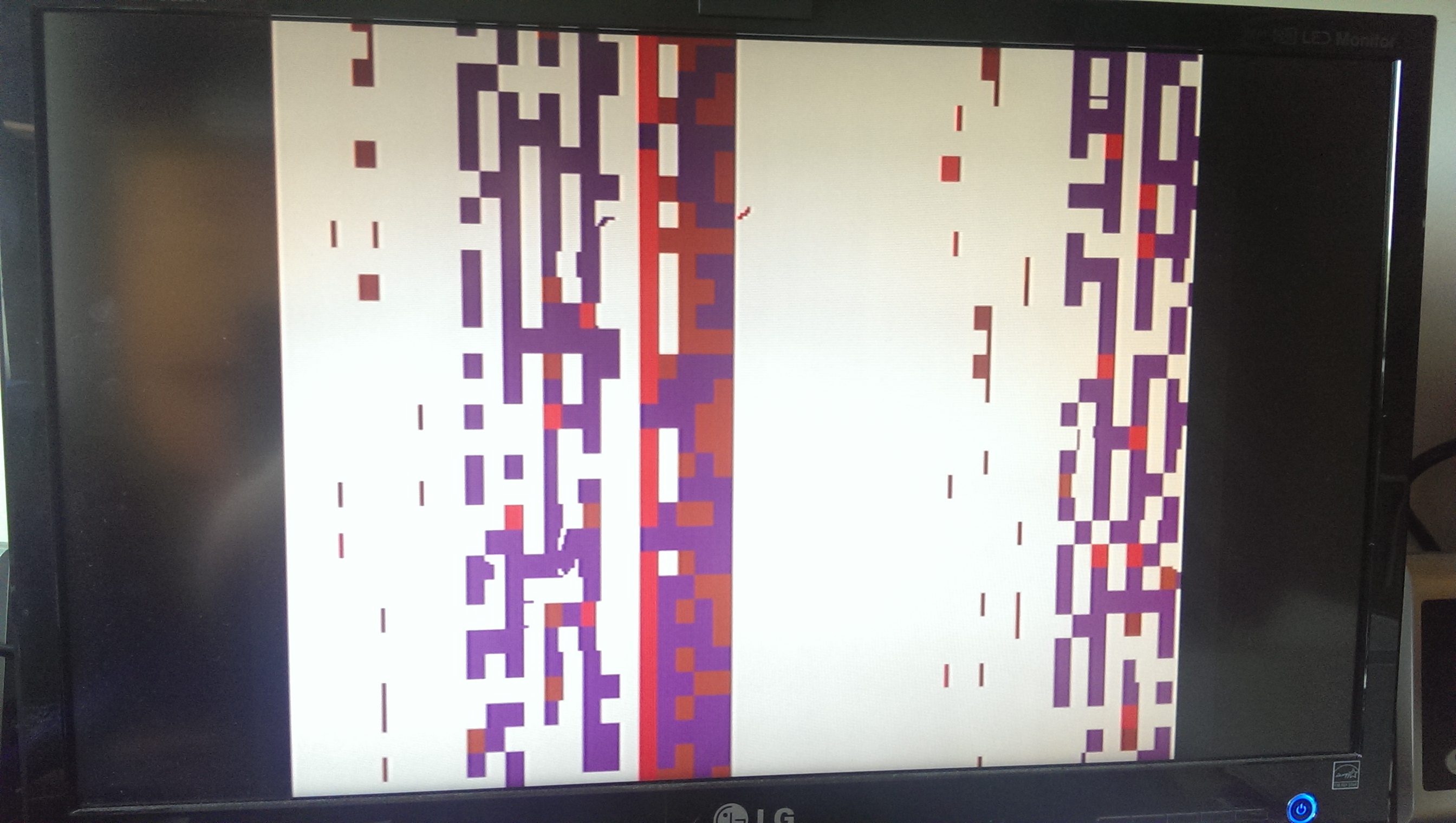
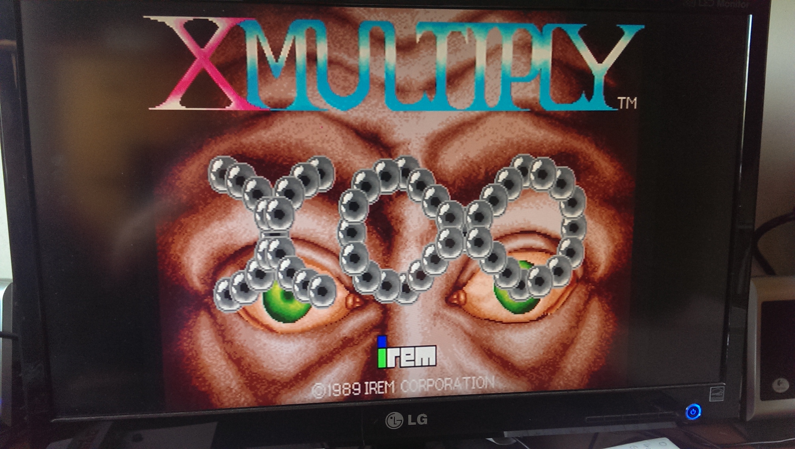
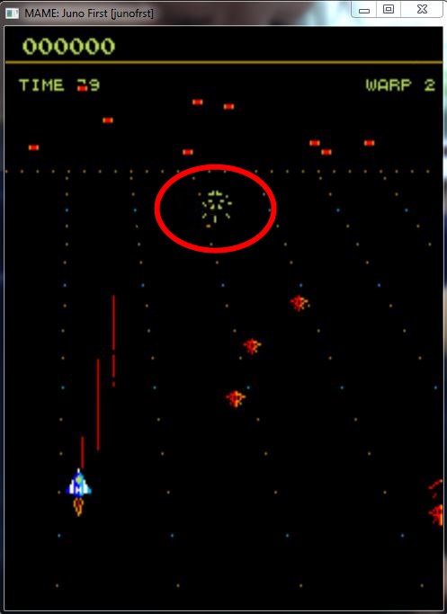
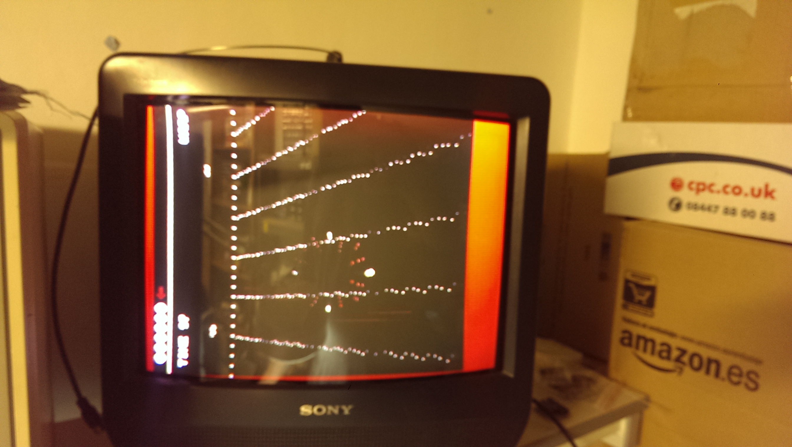
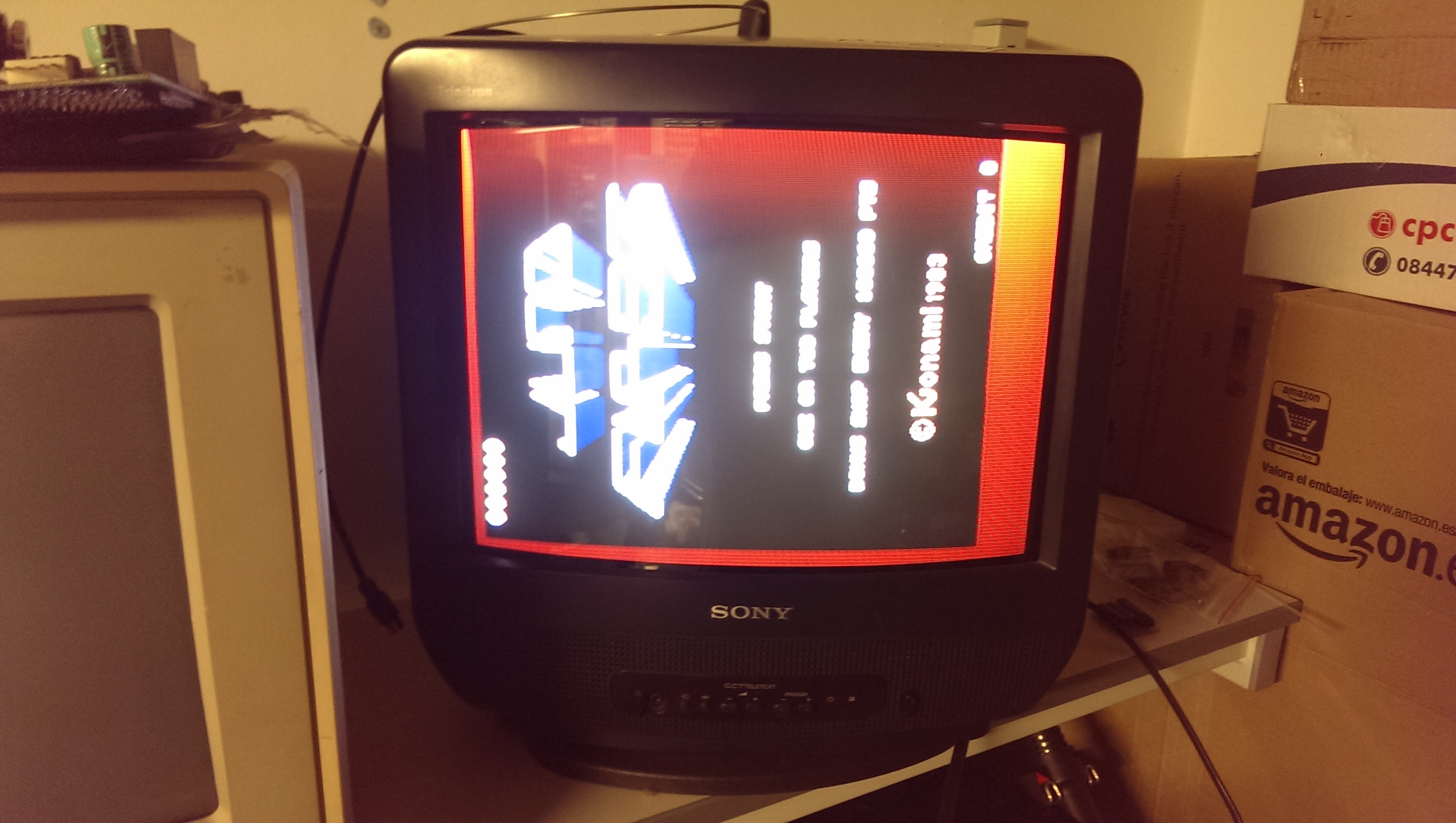
So now I have a booting game but all the sprites and title screen graphics are missing.

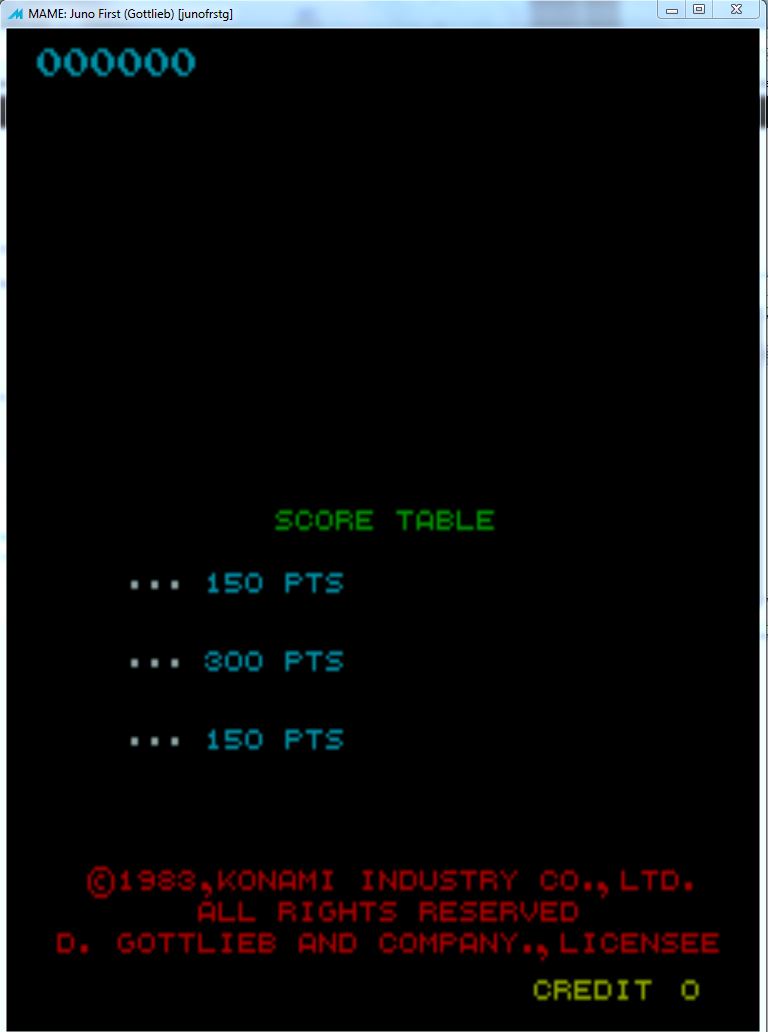
First thing I did was see if I could replicate the fault in MAME.
By creating empty files to replace ROM’s 7C, 7D and 7E on the top PCB I got the exact fault.

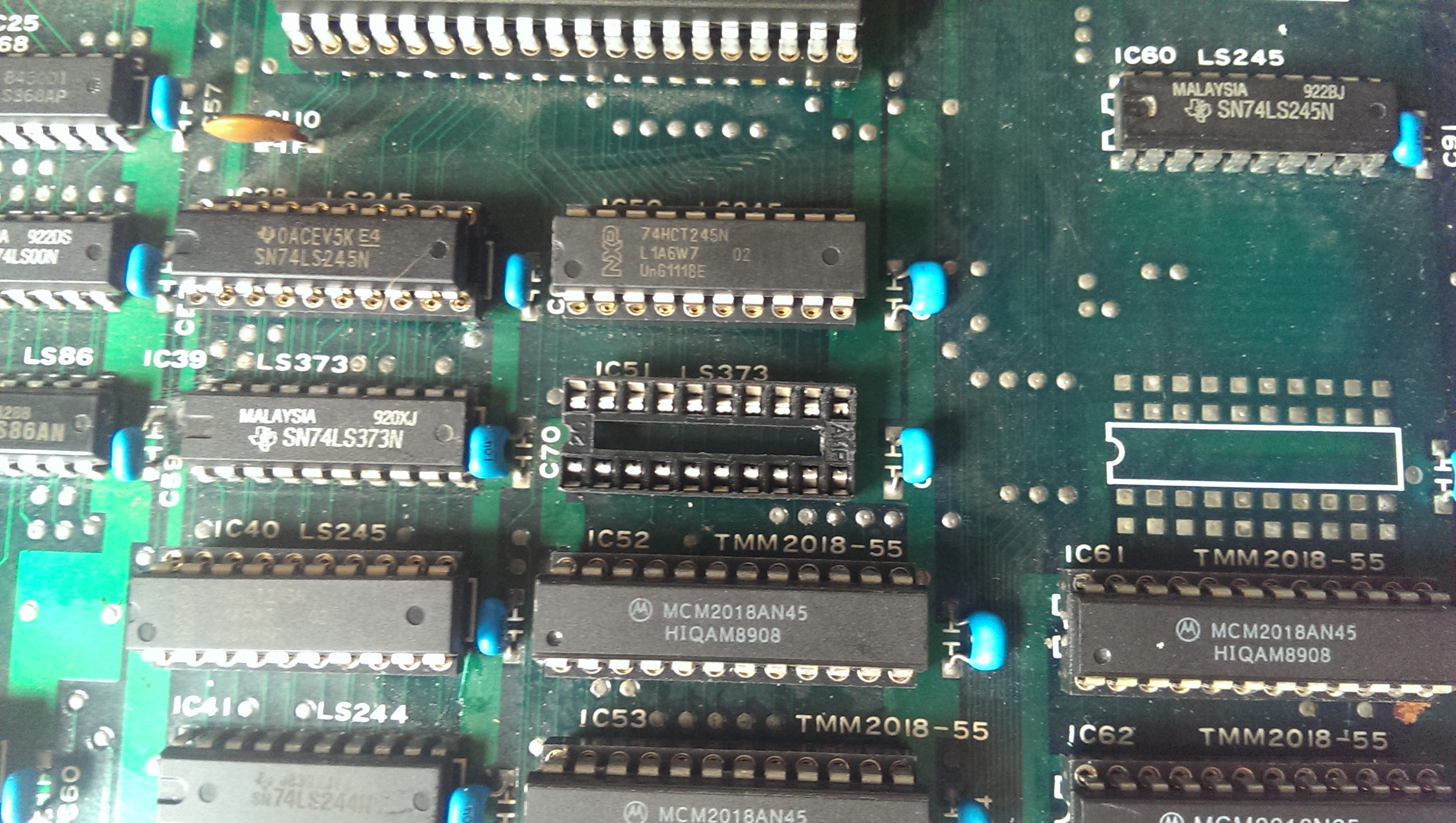
Checking those EPROM’s with the probe revealed that none of the chips were ever being enabled.
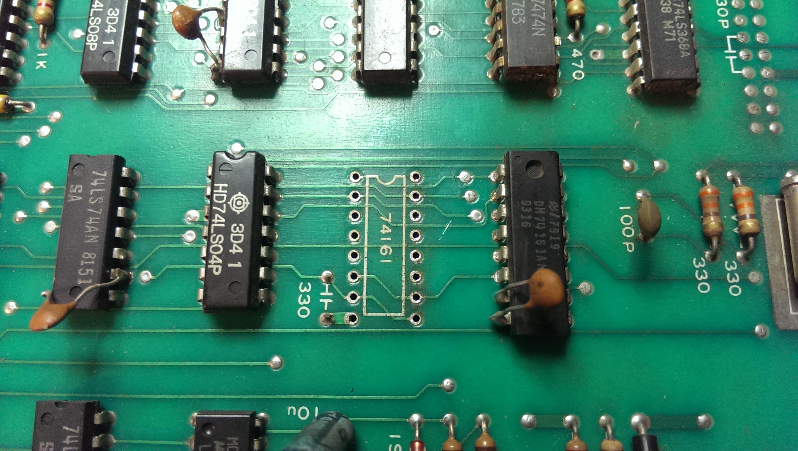
Following the schematics back to where the ROM selection lines are generated I came to a 74LS273 at location 6D on the upper PCB. Pin 11 is the clock pin for this chip and I would expect it to be pulsing but it was stuck HIGH. Following the /SSEL line back to the lower PCB led me to a 74LS138 at location I6.

This had pulsing inputs but either stuck HIGH outputs or floating pins. Replacing this chip gave me the graphics back.

That’s one down.

Silent Scope repair log

 PCB Repair Logs, Repair Logs  Comments Off on Silent Scope repair log
Jul 112011
 

Bought a Silent Scope PCB recently.
It had the “Hardware Error 11P” fault which is known to be cause by the battery failing in the TimeKeeper RAM.
Since the contents of these RAMs are in MAME I thought id fix one up which was probably a stupid idea as I dont have the setup to actually use it, but at least I know I can fix these now.

To get this thing booted up I modified my ATX power supply that I had previously modded to run my NAOMI setup. The power connection are labelled in the picture.

I had to run the VGA output through a standards converter too, it must be 31kHz. Once it was all fired up I was greeted to the startup procedure which consists of what look like RAM/ROM checks. All these passed but then it just hangs on the fault screen for a bit then resets.


The TimeKeeper RAM is located on the top board of a 3 board stack.

I removed the board and set to work desoldering the old RAM chip. It went smoothly considering it had the signature Konami thin traces and small through holes, the RAM just dropped out.

Thought it best to fit a socket in case of any problems with it in the future.
As this version shows up as v1.20, the RAM dump needed if from set UAB.
I did try reprogramming the original but it didn’t hold the data.
After fitting the new RAM the game booted to the test menu.


After working my way through the menus using the pins on the I/O board I was able to finally fire the game up.


So, I have verified that the sound works, the game boots and the digital inputs are working. I have no reason to believe that the rifle wouldn’t work if connected.

UPDATE (06/07/2015):
If you have an Arduino and fancy testing out my Timekeeper programmer ‘sketch’ then you can download it from the Downloads section.
It worked for me but I make no promises it will work for you. Its a basic proof of concept and could do with being developed.

Robocop repair log #1

 PCB Repair Logs, Repair Logs  Comments Off on Robocop repair log #1
Jun 152011
 

Bought a Robocop board from the AO forums. Seller says the jump button didn’t work.
Doing a visual inspection revealed a burnt out track just off pin 23 on the edge connector, which is button 2, in this case, the jump button.

image

I repaired the trace but still no joy with getting the controls back.
Further inspection showed that the custom resistor array had burnt out. This resistor array has some modified characteristics compared a normal array, it passes an input out to a different pin and has a few other differences too. As I don’t have any spares of the custom array I decided to use a standard one pulled from a scrap board.

image

To make this work I had to short pins 6 and 7 together and 8 and 9 together. These are for button 1 and button 2.
The board is now fully working but ill keep an eye out for an original replacement part to fit.

Commodore 64c repair log

 Computer Repair Logs, Repair Logs  Comments Off on Commodore 64c repair log
May 282011
 

The data cassette player would not power up and there was no sound outputted.
There is a big 1.5A fuse inside labelled F1. This supplies the +9v to pin 28 of the SID chip and is also used in powering the cassette unit.
Replacing this fuse brought everything back to life.

The C64c boots up fine without this fuse. I have been using an SD2IEC adapter to load games and didn’t realise at the time that the cassette unit was not working either.