Oct 022014
 

To start with this game wouldn’t boot at all.
The board has had one of its big surface mount custom chips replaced in the past and apart from one lifted track that has been patched out, the swap was very neat.
First job was to desolder the sub CPU and fit the Fluke to see what was going on.
I found a broken link between the ROMs and D4 of the CPU. I patched this and did a ROM check.

The ROM address space lies between 0x0-0x3ffff.
The Fluke 9010 signature for this is 8A4F

This was correct but the game still refused to boot.
Checked the RAM. This lies between addresses 0x20C000-0x20FFFF
Both of these failed and both were replaced.
Ram checks now pass but the game still does not boot.

Next I tested the shared RAM.
This lies between 0x210000-0x21FFFF
This passed up until address 0x21FFFE where I couldn’t write to the address at all.
I haven’t figured out why but I’m starting to think this is normal as the code writes to this address space separately but never reads from it. Maybe some kind of watchdog reset or something?

As the game still did not boot I opted to desolder the main CPU and fit the Fluke there.
Found another broken track between the main CPU and one of the ROM’s (I forgot which one as this repair has taken ages).
I patched this out and the game now boots but there is a faint output on screen. Further probing with the scope revealed a dead TC0070 RGB custom chip.
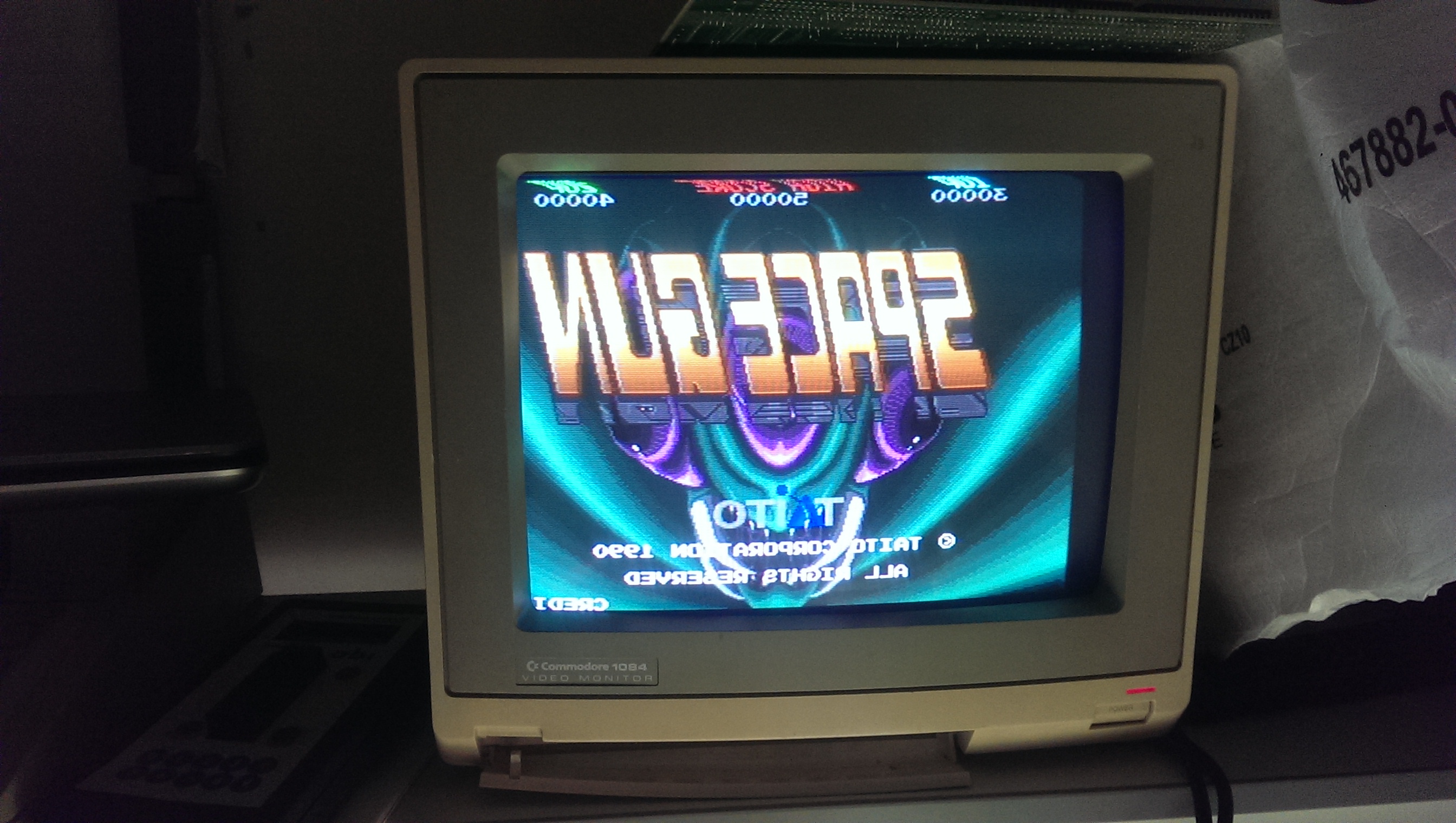
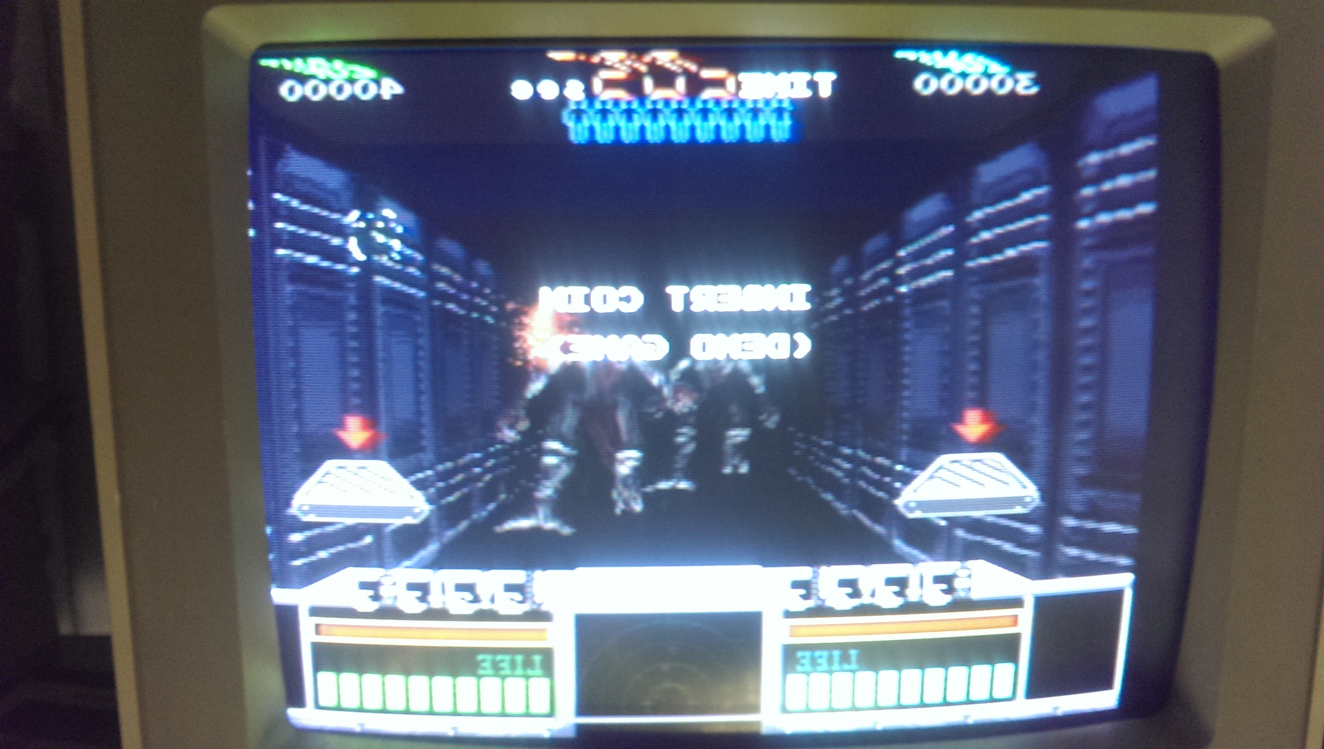
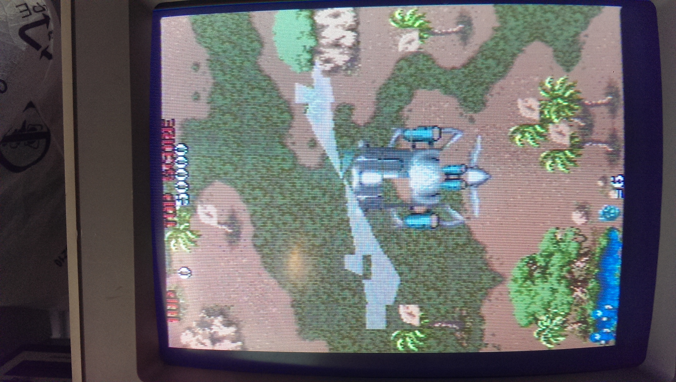
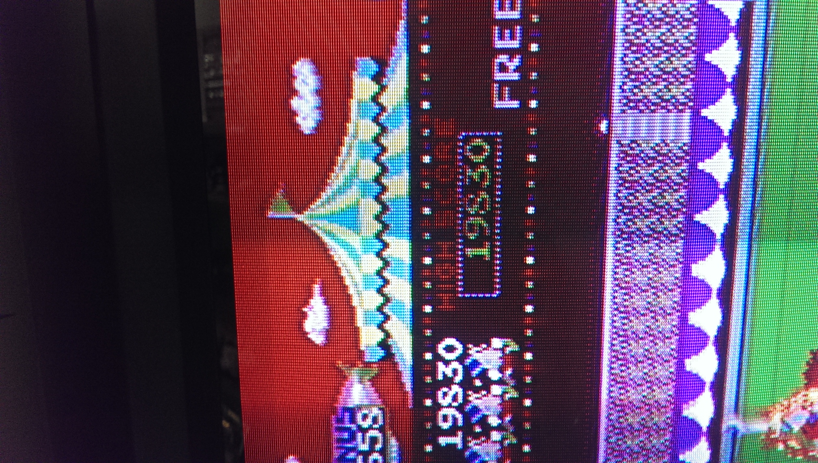
I replaced this and now got a booting game but with wrong colours.
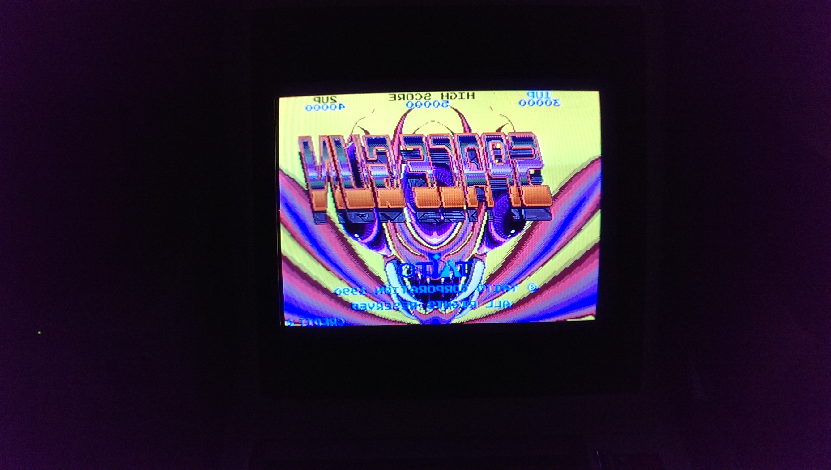
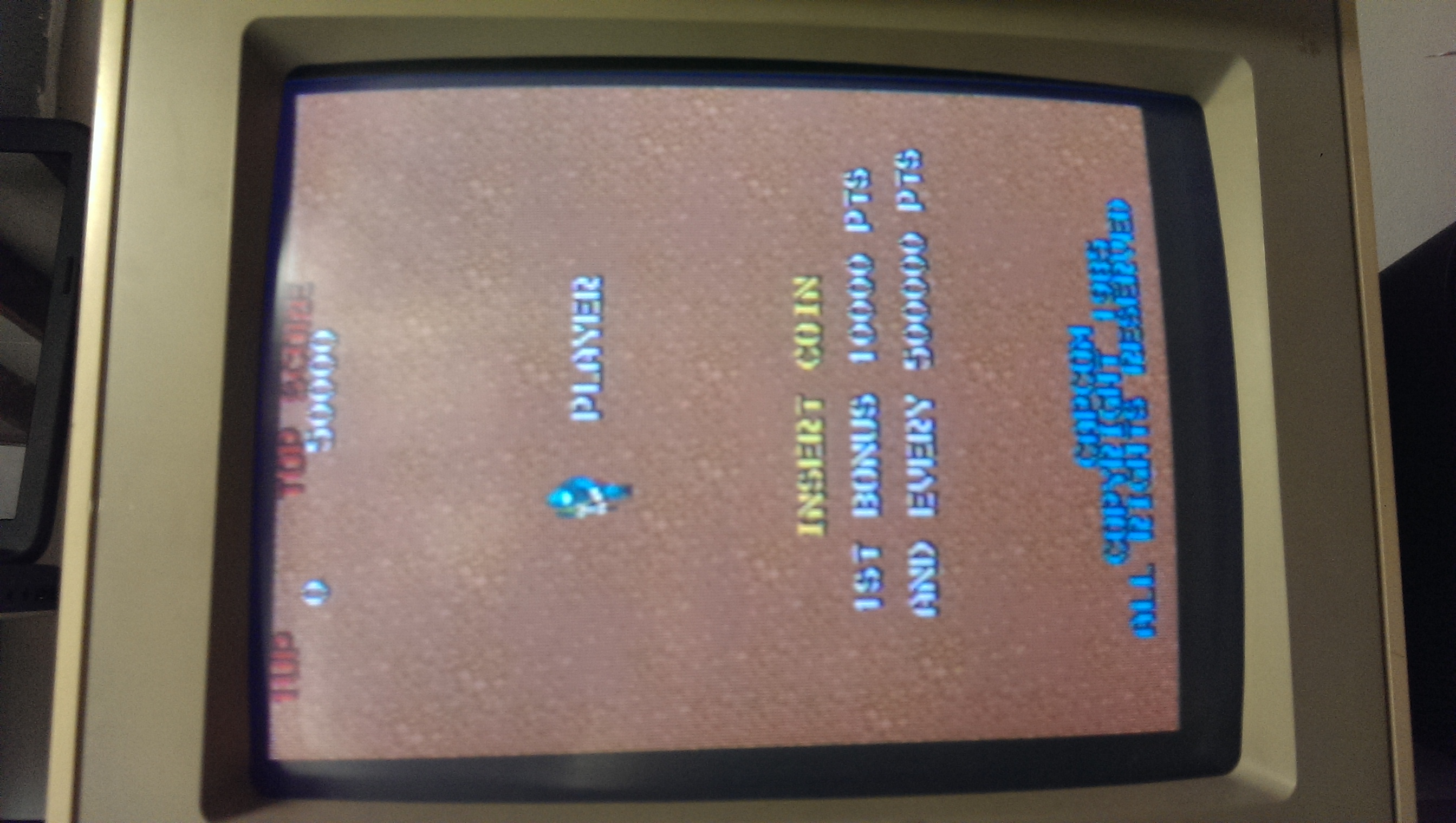
IMAG0883

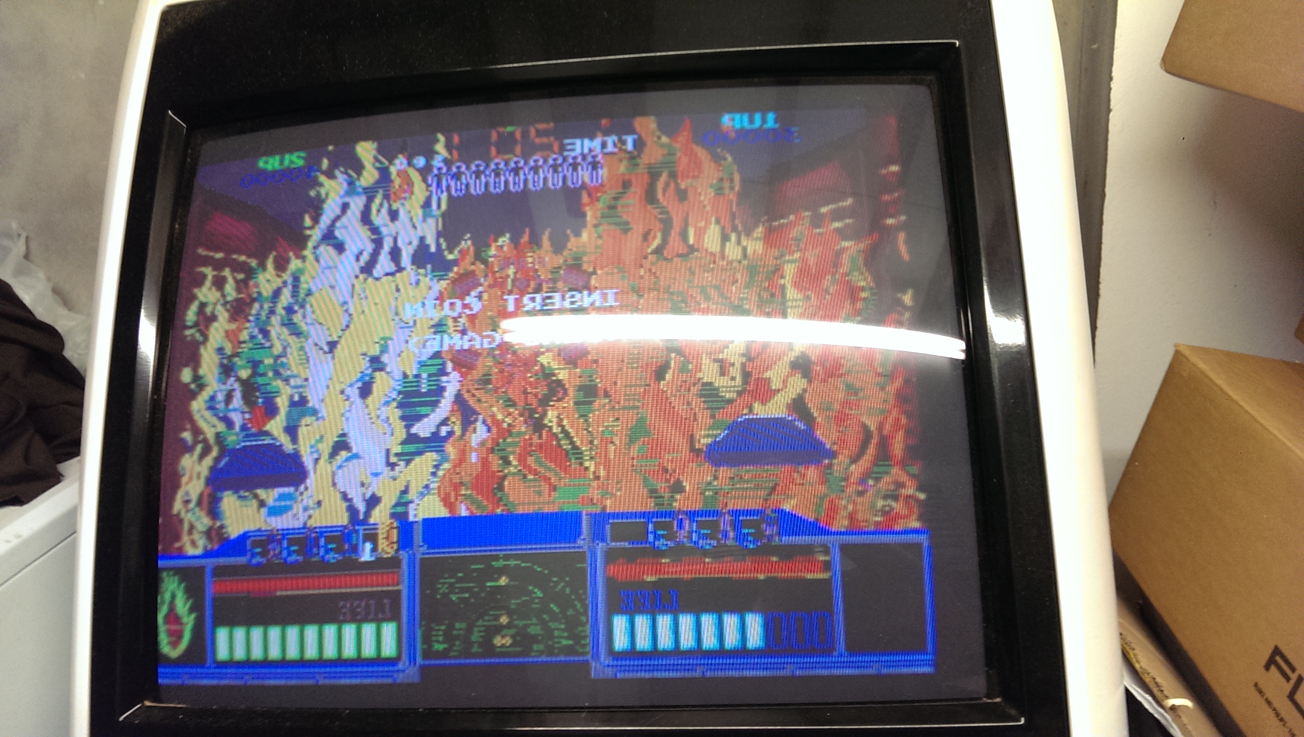
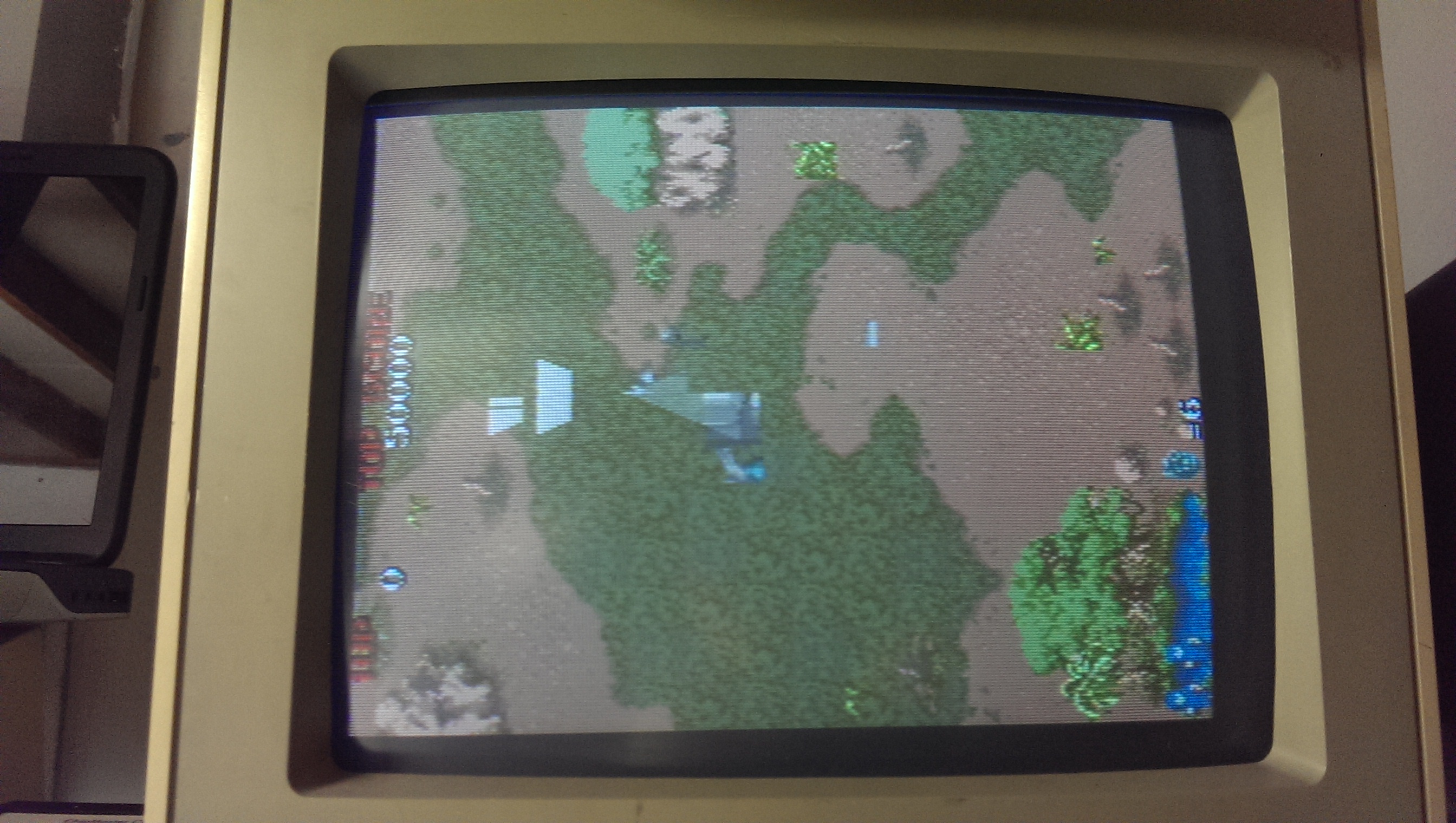
IMAG0885

This had me stumped for a while as there are a lot of custom chips on this board and any one of them could be a suspect as they all feed into and out of each other.
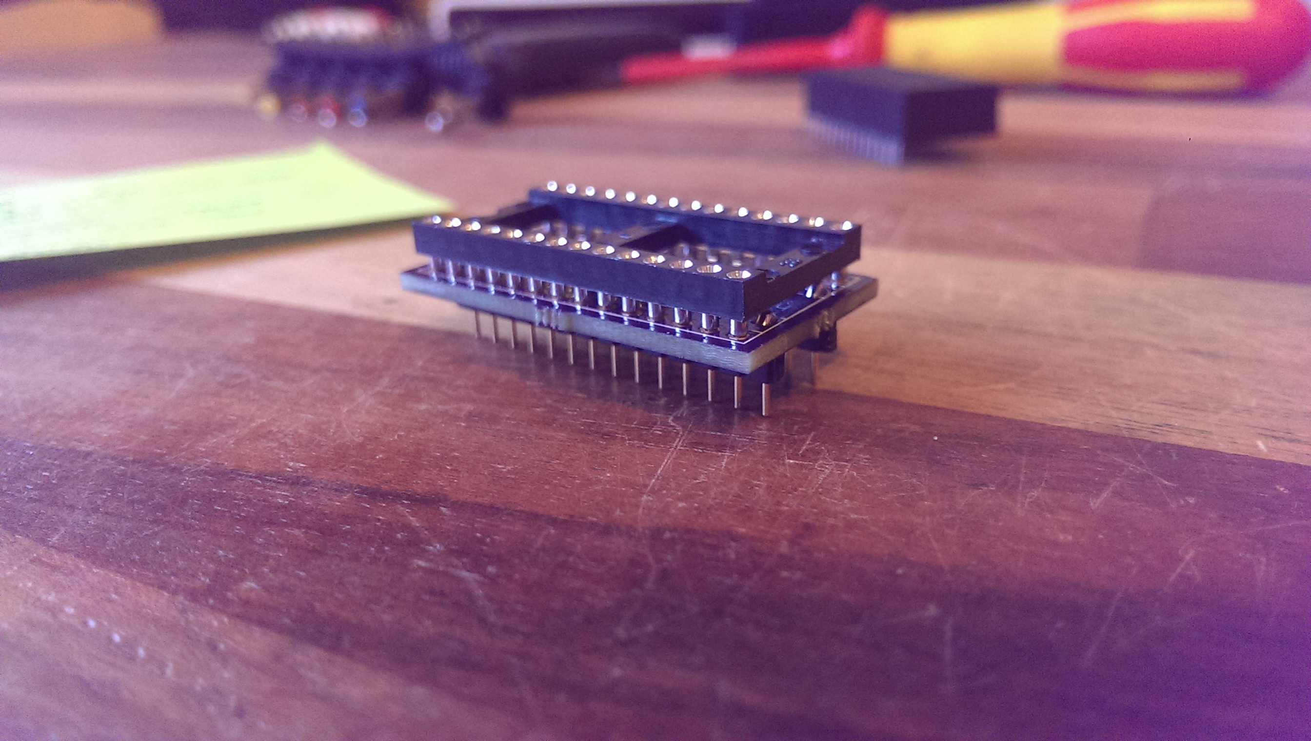
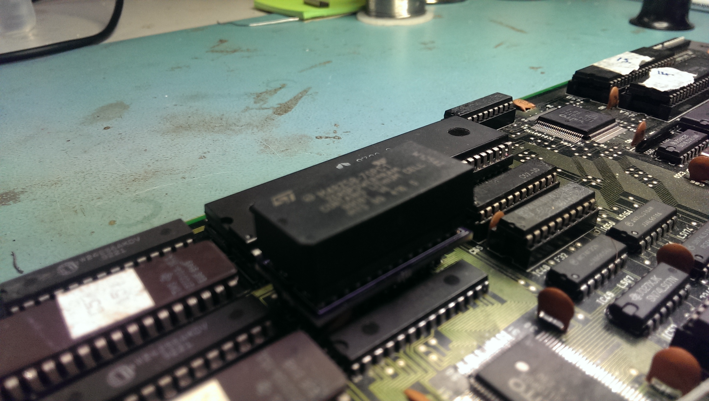
I opted for a different approach to normal and made up a small converter PCB that let me use 0.6″ chips in place of 0.3″ chips. This allowed me to use an NVRAM chip in place of the palette RAM.
IMAG0948

IMAG0933
So with this in place I let the game boot to the title screen and powered off. With the contents stored in the NVRAM I was able to dump it and repeat the operation for the second palette RAM and interleave the dumps together. No I had this I could compare it to what MAME has at the same point. This allowed me to see if the data being written was actually correct or not.

Here is what I got on my first attempt and what I should have got.
SGwrong
SGright

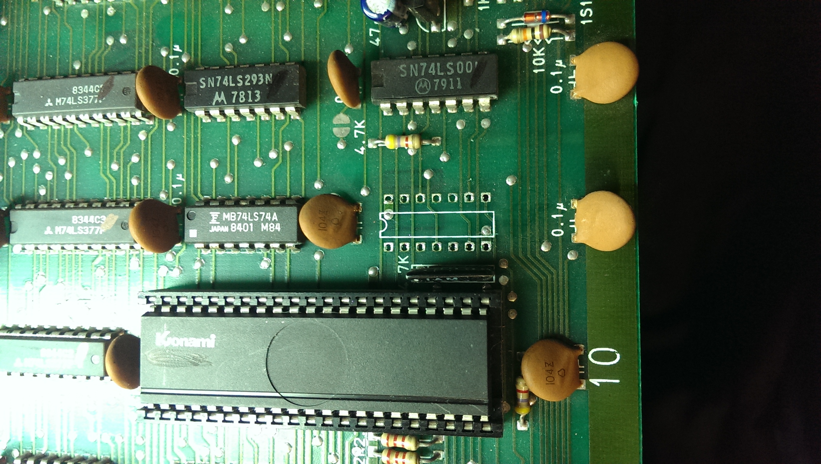
As you can hopefully see, bits 4 and 6 are wrong here so I took a closer look at the custom chip TC0110PCR that feeds the RAM chips.
IMAG0934

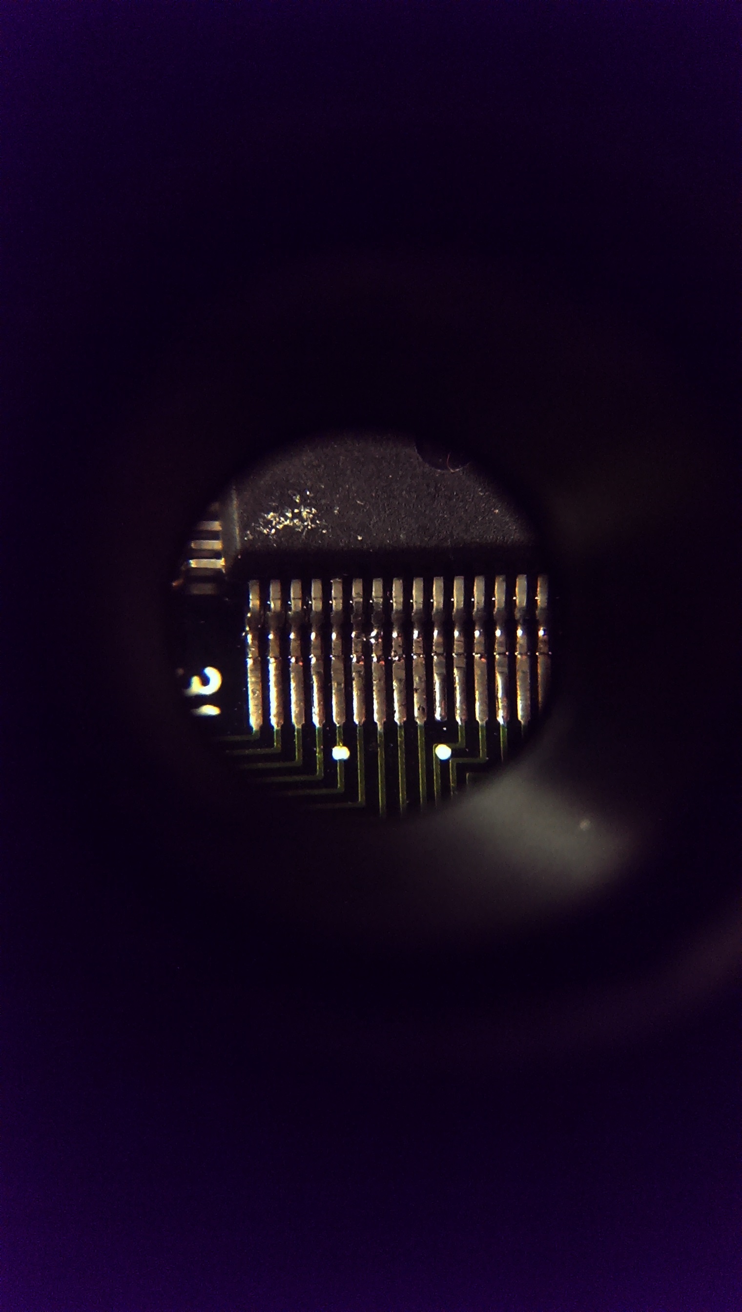
There was the smallest bridge of solder across D6 and D7. Removing this gave me the colours back.
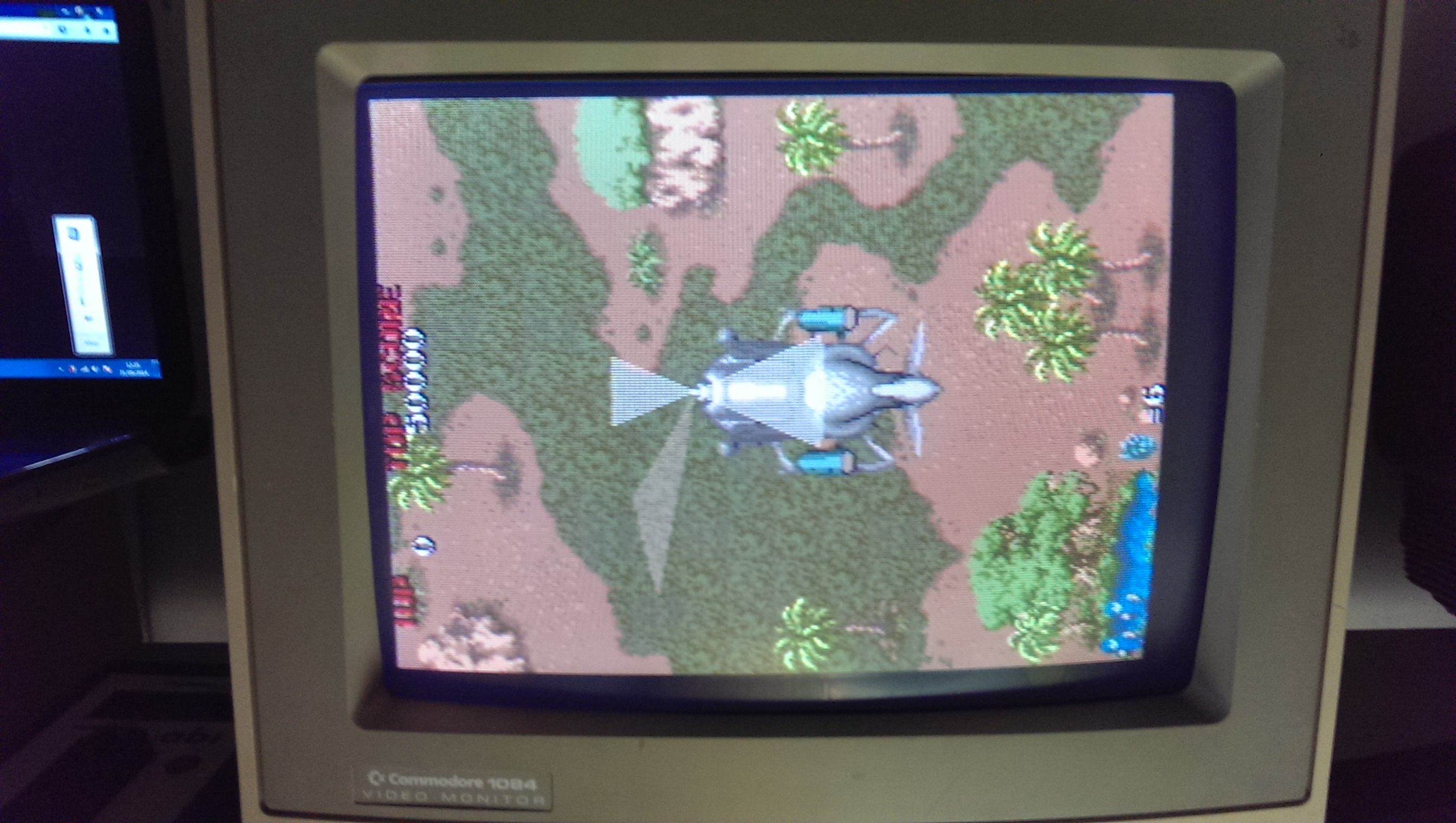
IMAG0944

IMAG0945

Everything else appears to be working so I am glad this is now sorted.

Sep 212014
 

Another one of Ben’s boards.
Had the usual graphics issues you normally get associated with those four 2114 RAM’s only this time the RAM’s had already been replaced and all four were good.
IMAG0908

Following the inputs and outputs from these RAM chips I found some broken traces, probably a result of desoldering them originally.
Pin 1 of the RAM at location 3H was not connected to anything. I patched this and it fixed the solider sprite on the title screen but some in-game graphics were all messed up.
IMAG0909

IMAG0910

After confirming all other connections were good I noticed two other 2114 RAM chips that had been worked one and socketed so I checked those too.
Initially I found pins 3 and 4 of the RAM chip at 1B. Patching these gave me this result
IMAG0912

Getting there but not quite.
A little further inspecting these chips and I also found pin 15 of the same chip not connected to GND like it should be.
Patching this one gave me a perfectly working game.
IMAG0913

IMAG0914

Aug 302014
 

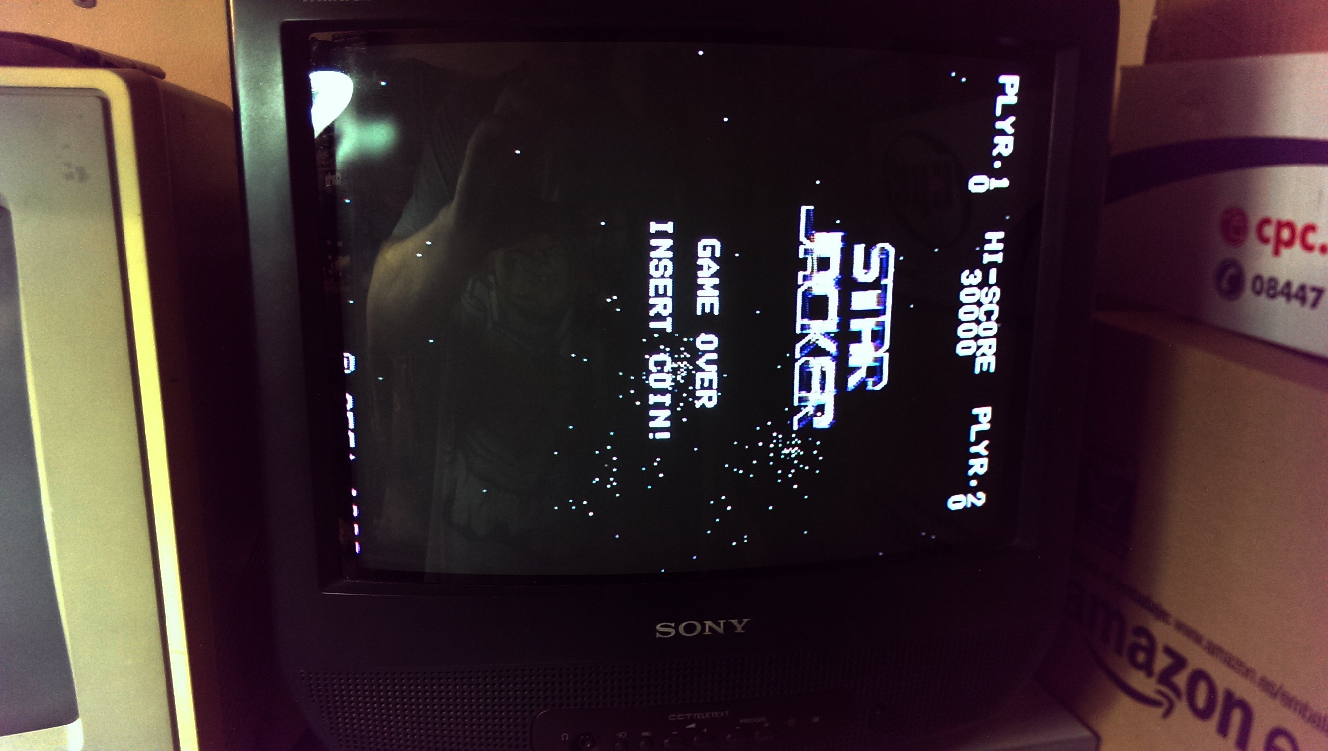
Got a mammoth box of boards from Ben76 the other day. This Star Jacker PCB is one of them.
Game gave a black screen when powered up and there was no sync signal.
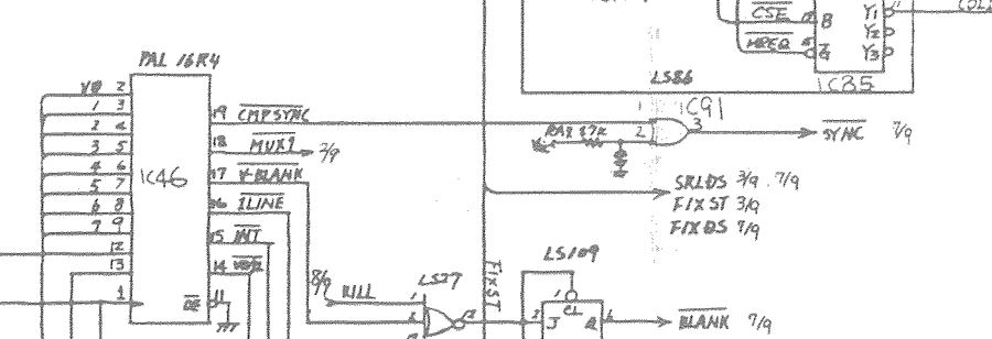
Ben also gave me a scan of the schematics for this board so was quickly able to determine where the sync came from.
My heart sank a little bit as the sync comes from a PAL16R4 chip
sj-sync

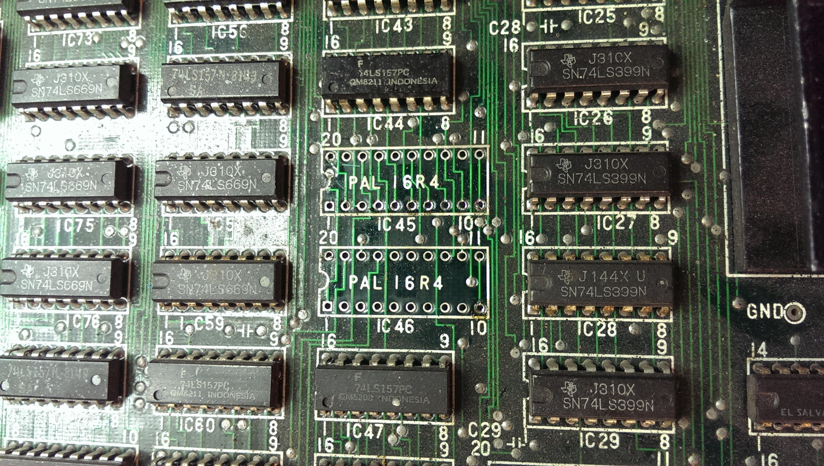
On investigating I found the VCC pin was not making a good contact in the socket so I removed both of the PAL sockets and replaced them.
IMAG0839

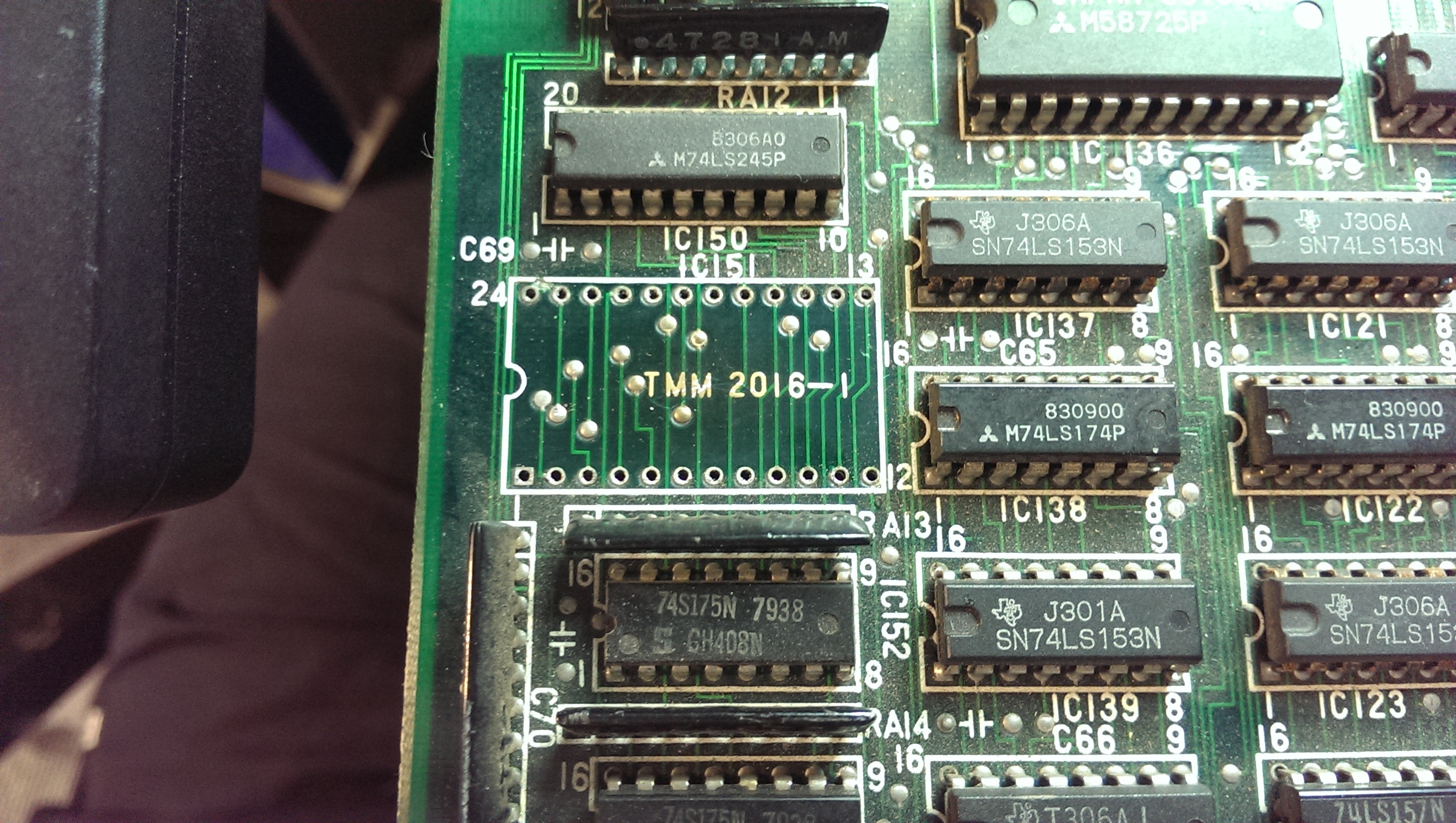
So booting now gave me sync but solid white screen. Ive seen this before on quite a few boards and its almost been RAM issues. I started probing the RAM chips and found a 2016 SRAM at location IC151 had completely dead outputs despite being enabled and having active inputs. I desoldered it and replaced it with a 6116 SRAM chip.
IMAG0840

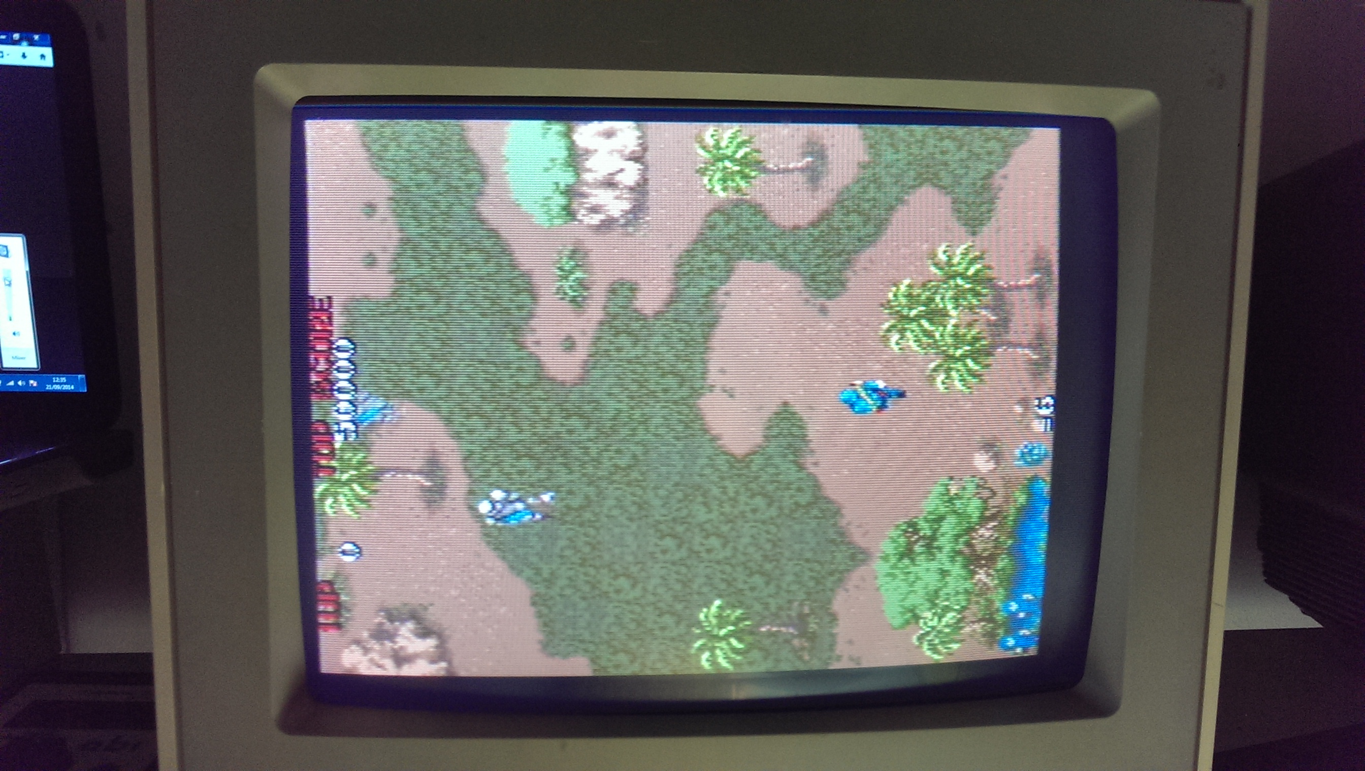
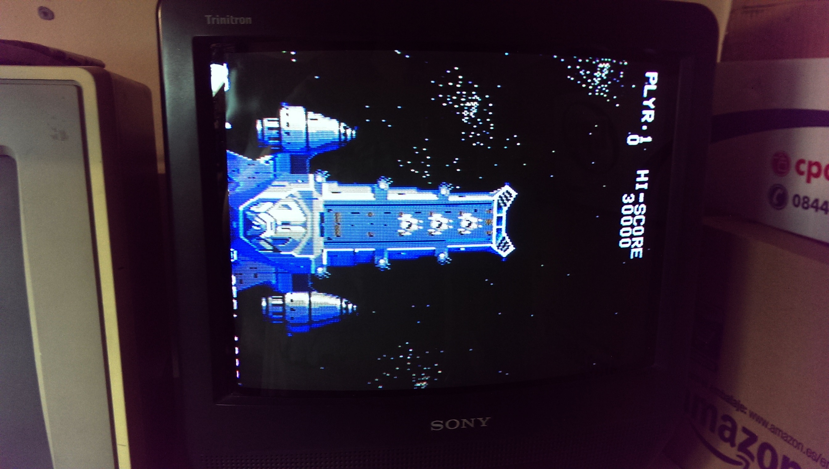
Now I get this (NOTE: the red colour is actually present but I have to edit my pictures these days as the HTC One makes low light pictures all purple)
IMAG0842

IMAG0843

All fully working again.

Aug 272014
 

Game was dead on power up.
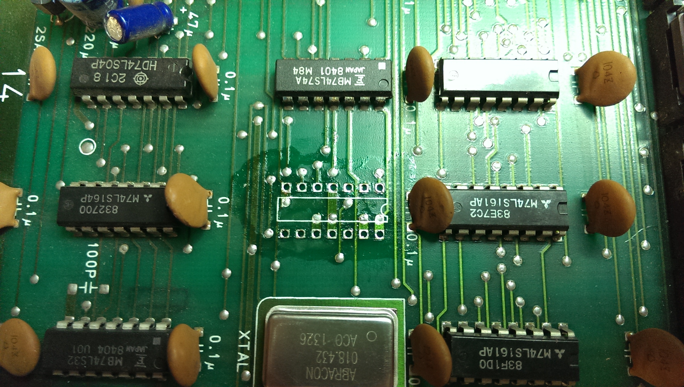
Pressing down on the crystal brought clocks back. Resoldering the crystal didn’t help so there must have been a break internal to the unit. I ordered a spare 18.432MHz crystal oscillator and waited for it to arrive.

The new crystal arrived and fitting it brought the main clock back however my monitor screamed at me.
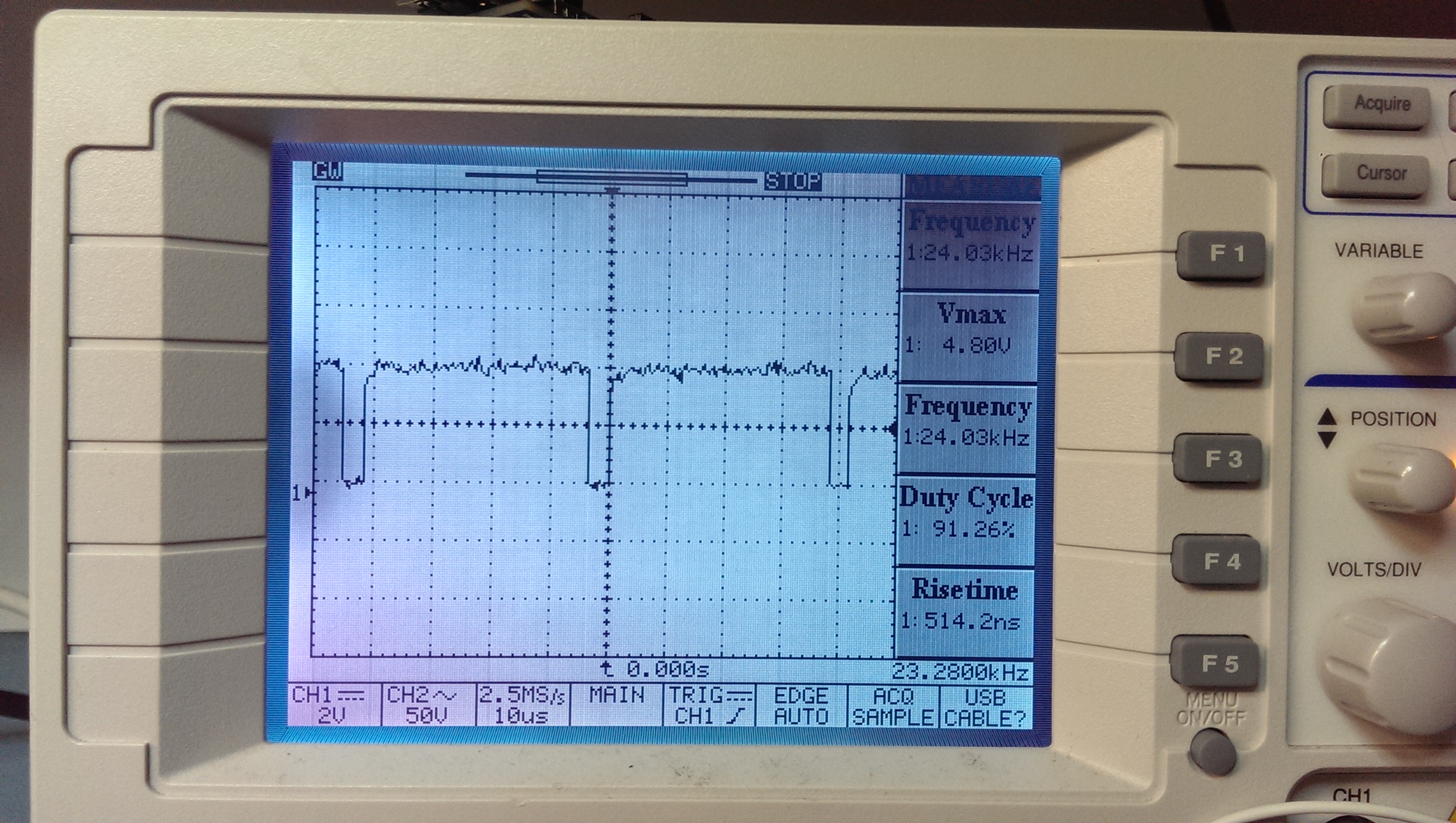
Checking the output from the 082 custom chip on the scope revealed that the SYNC signal was around 24kHz.
wrongkhz

I originally thought the 082 was at fault as id seen so many of them go wrong before but after sleeping on it I started to think this unlikely. At this point I asked for a bit of help from forum user cmonkey. He knows a lot about Konami hardware and has provided a lot of insight to me in the past.
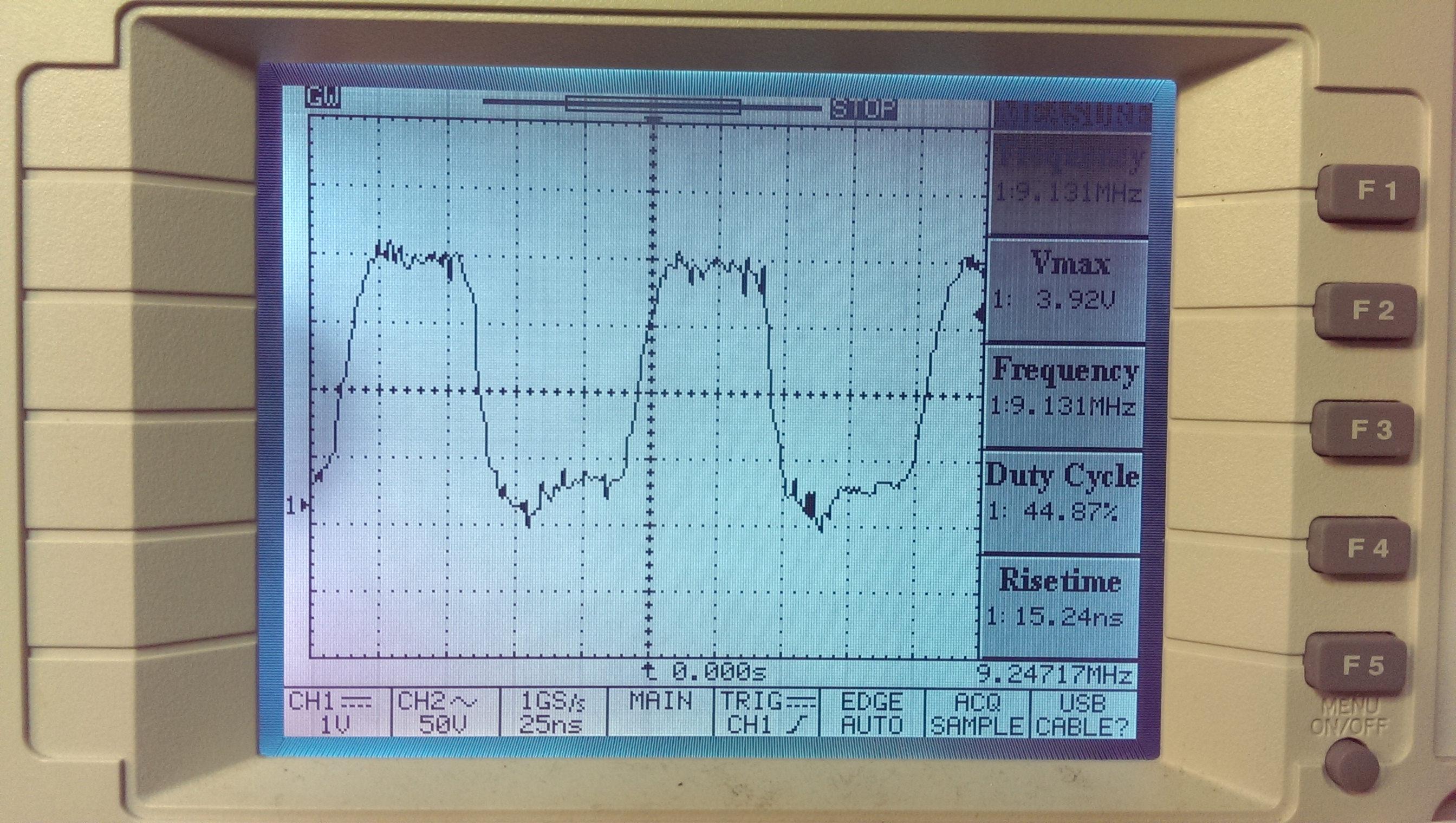
He very generously took some measurements off his Gyruss PCB and it confirmed that the clock input going to the 082 was too high on my board. It should be 6.14MHz into pin 13 and I was getting around 9.14MHz.
wrongkhz2

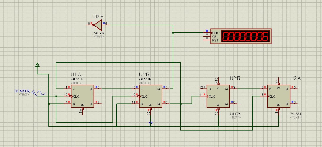
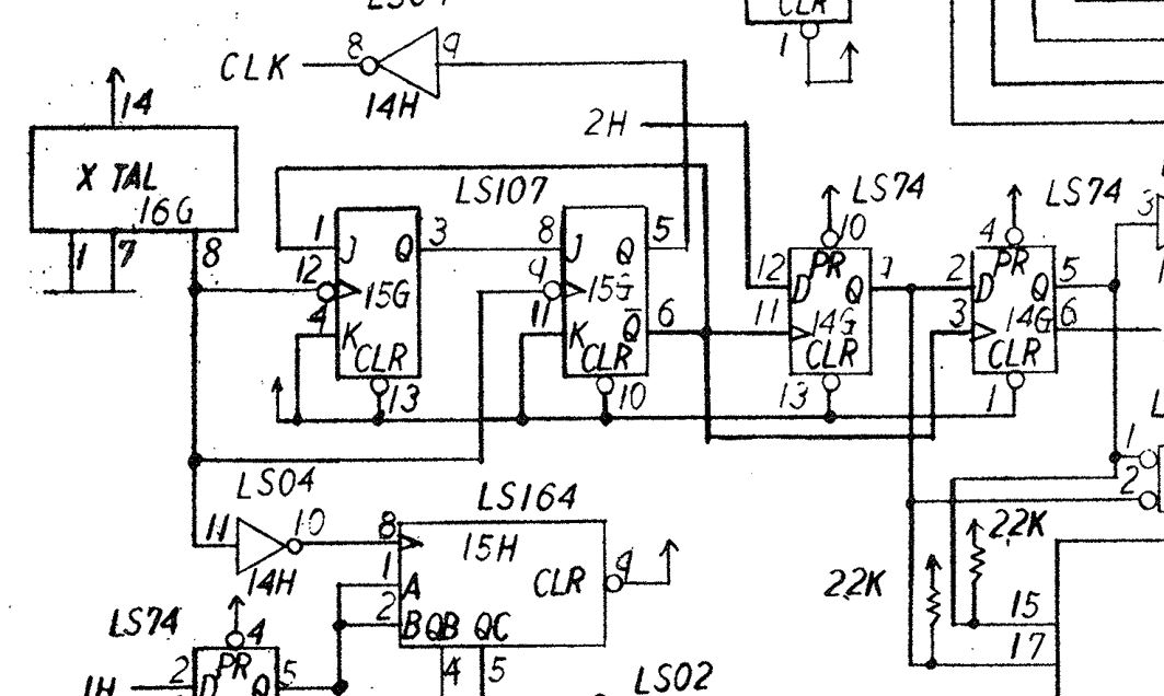
At this point I thought I would do a bit of circuit simulation and drew out the clock generation circuit in PSpice.
cc-sim1

This is how the circuit should be.
ccharlie-clock

As you can see from the simulation I have around 6MHz.
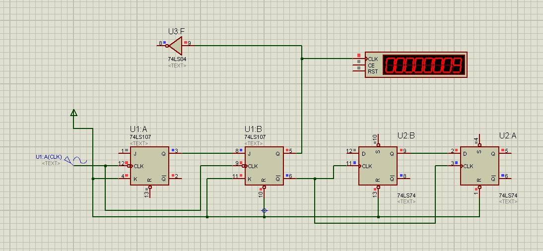
Probing around this PCB however revealed that pin 1 of the 74LS107 was dead. Removing this line from the simulation revealed this:
cc-sim2

Exactly what I was wanting to see.
I removed the LS107 and tested it. It failed as expected.
cc-107fail

I found one on a scrap board. This brought everything back to life.
ls107

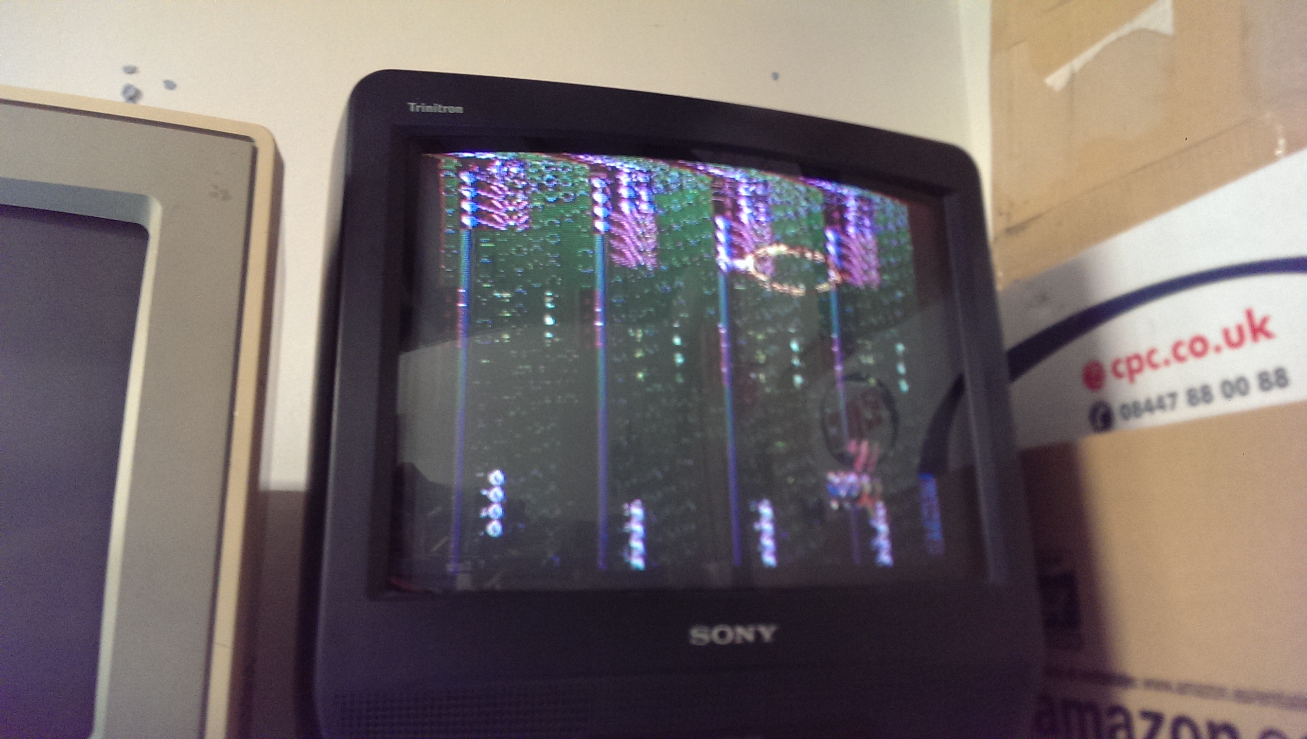
Powering the board up initially gave me a static screen of 0’s. This is what you normally see during the start of the POST. Ill get back to this issue later.
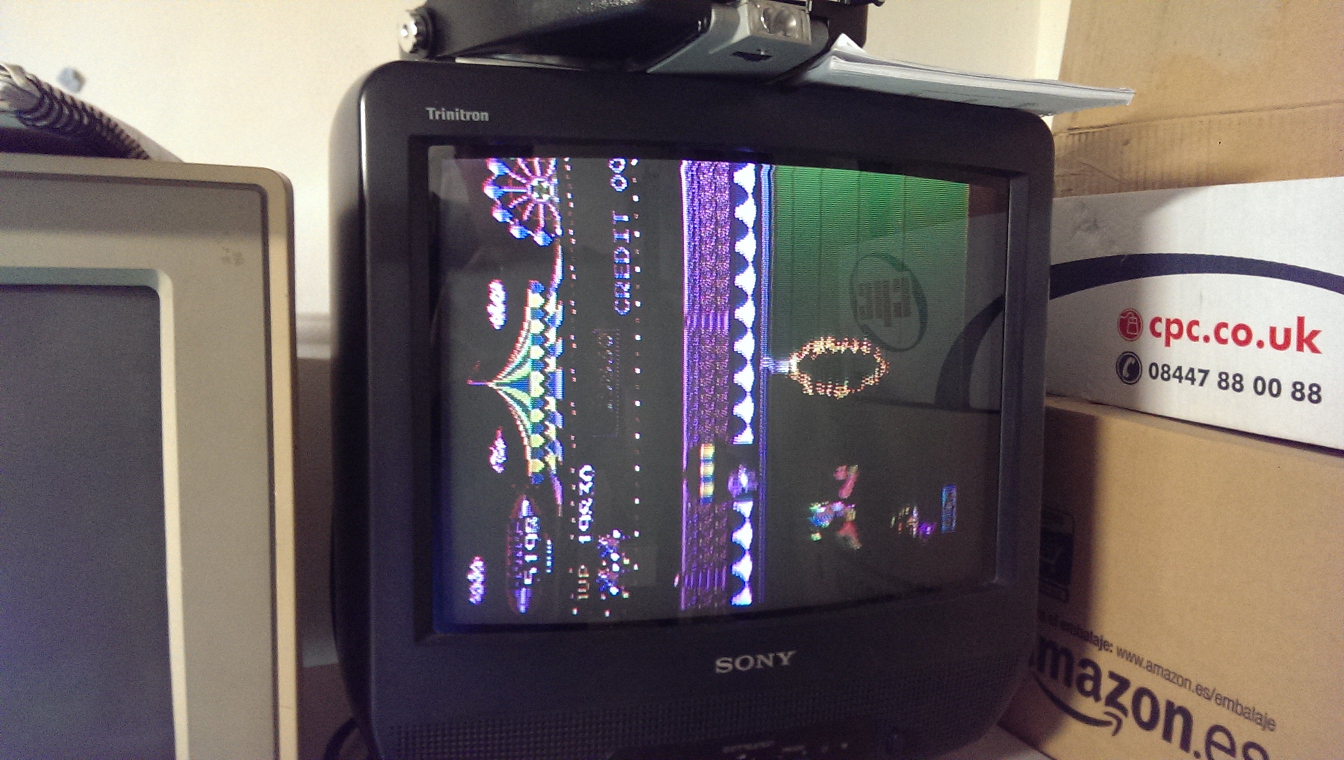
Powering down and back up again gave me this:
rightclock

Using MAME I confirmed the Video RAM area was to blame.
Checking the address lines on the 8128 RAM at location 3E revealed 4 dead lines. I traced these back to 74LS157 at location 5E. Replacing this brought back the graphics.
almost

There is still a small graphics issue at this point which I struggled to find and also the intermittent power up problem I mentioned earlier so thought I would move on to the other issue of the controls not working.

Neither of the coin inputs work.
Back to the schematics, I can see where the signal comes in and taking some measurements shows there is something wrong as I’m getting around 1v at pin 6 of the chip at 3F.
There is very little to this part of the circuit and the resistor array looked good so I desoldered the 74LS253 and it failed all tests. Replacing this brought the controls back.

So back to my remaining problems.
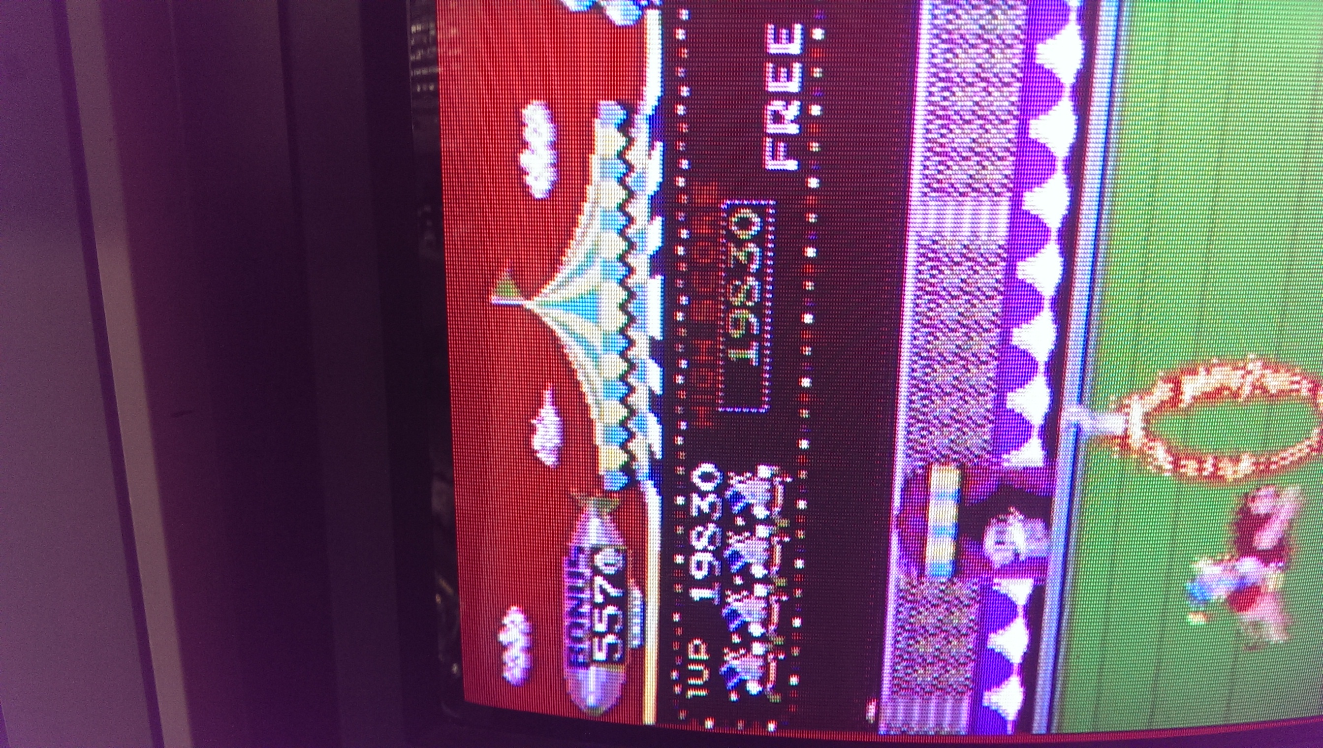
First, the graphics issue. Its hard to describe but on the parts of the screen where the coloured dots cycle round this also affected half of the 8×8 tile above it.
IMAG0820

As it only affected half the tile I eventually came to the conclusion it was a timing issue. This led me right back to the beginning where the reset circuit lies.
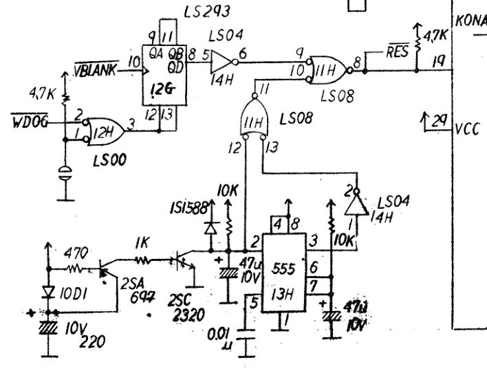
The power on reset is generated by a 555 timer which goes through a bit of logic and eventually out to the rest of the board as a /RES signal.
cc-reset

This signal comes out on pin 8 of a 74LS08 AND gate. Working back I found I had no output on pin 11 at all. I desoldered this chip and replaced it.
IMAG0816

It fixed the reset problem but also fixed the graphics problems too
IMAG0821

I guess it could have been caused by a timing issue after all?

This board looked is VERY good condition and, looking at the edge connector, it cant have been powered up more than a handful of times so its interesting to see that all these problems were present.
Very pleased I got this fixed.
X Multiply repair log #3

 PCB Repair Logs, Repair Logs  Comments Off on X Multiply repair log #3
Aug 112014
 

Yes, again.
During some playing of this recently repaired board the game froze up.
On reset I was greeted with this static screen.
IMAG0758

Non booting boards are generally quite easy to fault find but due to the V30 I was having problems. This is when I came across a post on KLOV from some time ago with someone asking if an 8086 Fluke POD could be used to test a V30 based system. The general thinking was that it could but no one ever tried it, until now!
Im pleased to say it does work (excluding the RUN UUT function).

Very quickly I found that the main ROM’s could not be read properly. The correct signature was 6A03 and I was getting 6935.
Following my schematics I found that there is a 74LS373 at location IC51 that is used as the latch to address the ROM’s.
IMAG0759

This input was confirmed good but there was a stuck bit on the output.
I replaced this and the game was back once again. Ive left this soak testing and hopefully it will be rock solid now.
IMAG0761

So just to confirm. The 8086 pod for a Fluke 9010/9100 can be used to check V30 based systems.