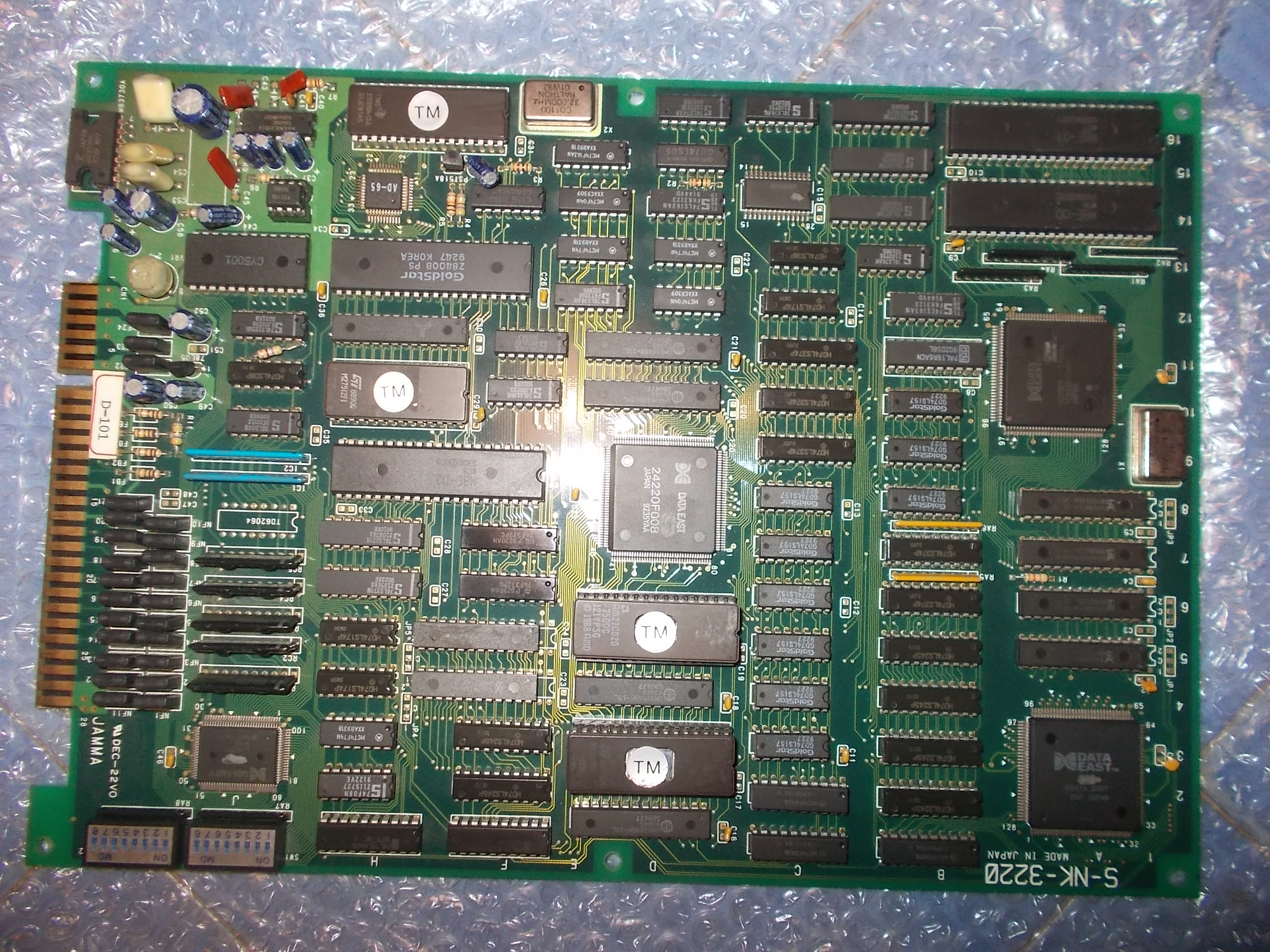
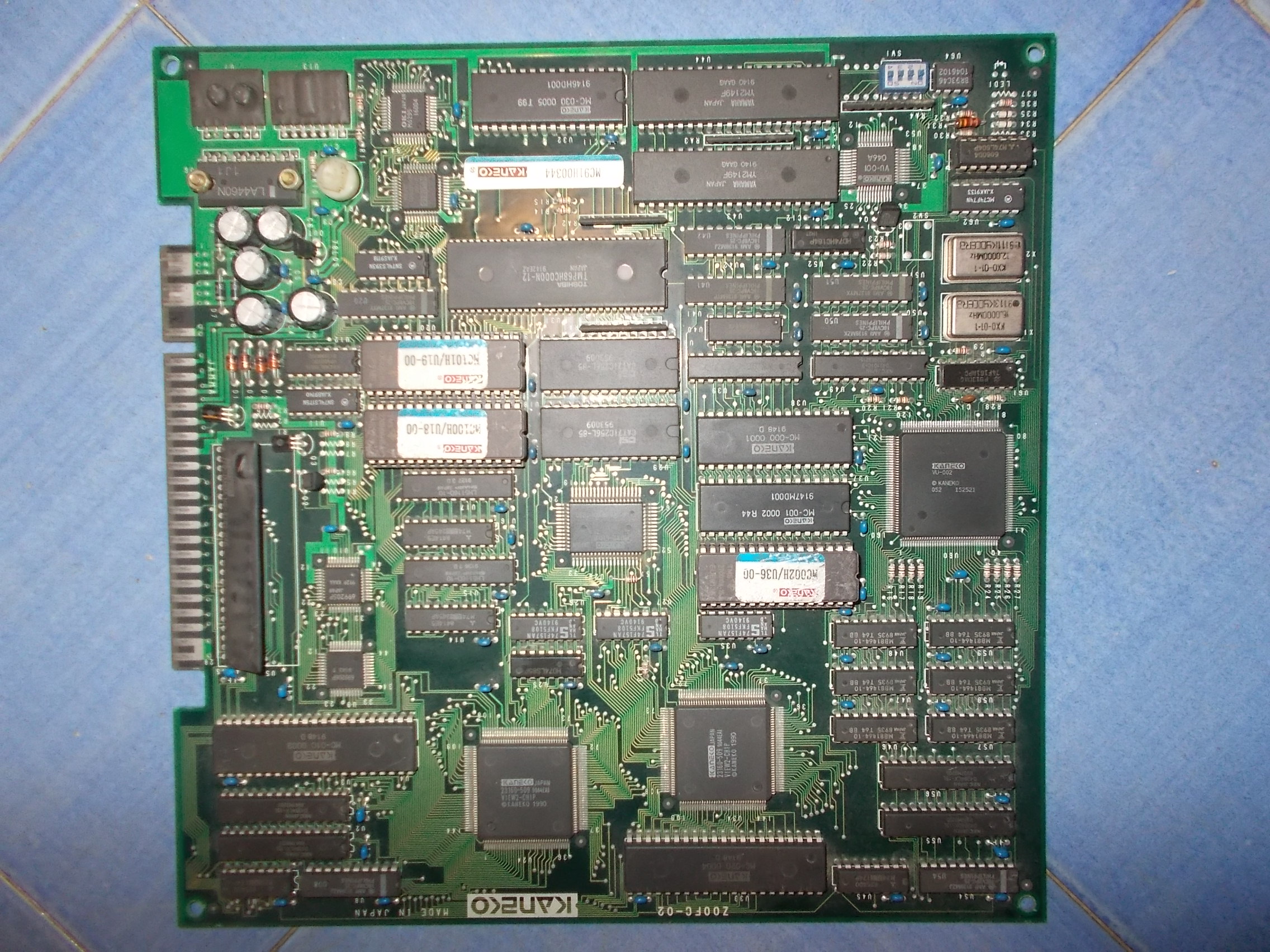
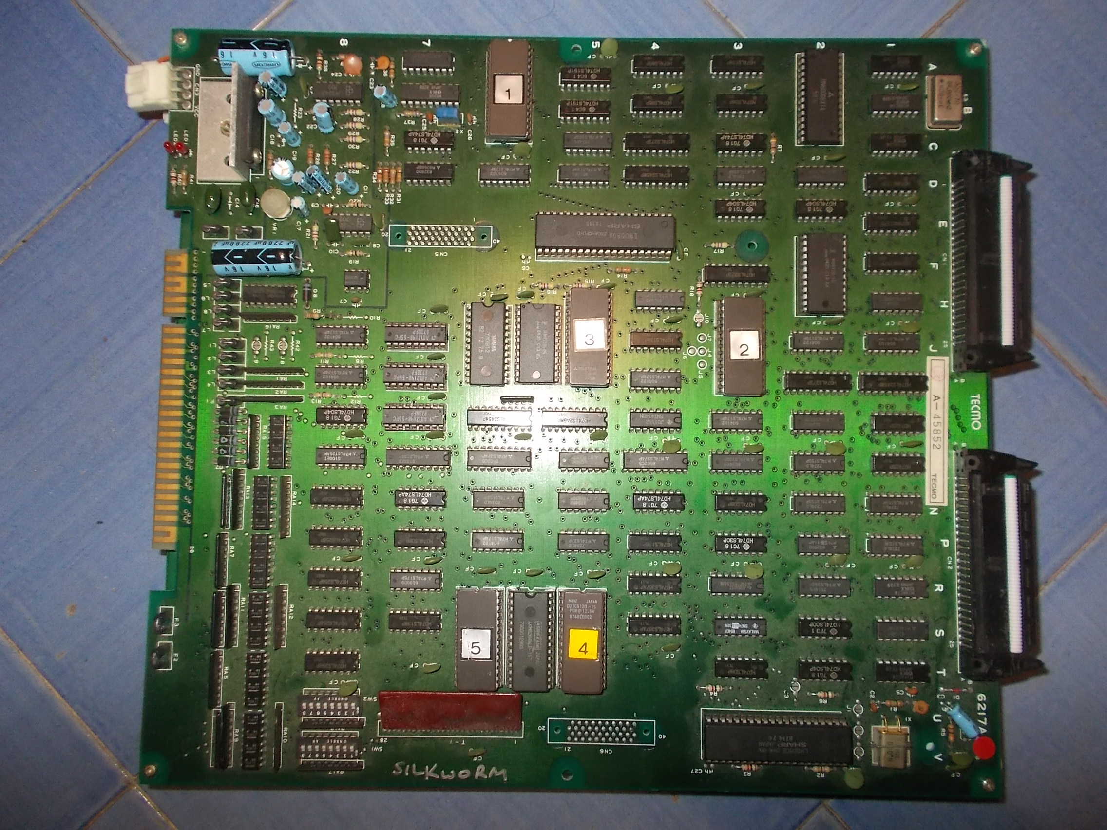
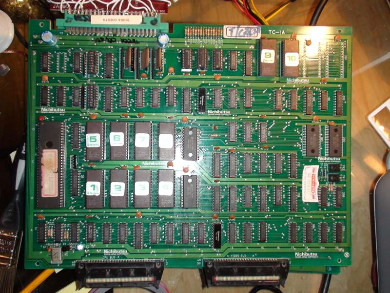
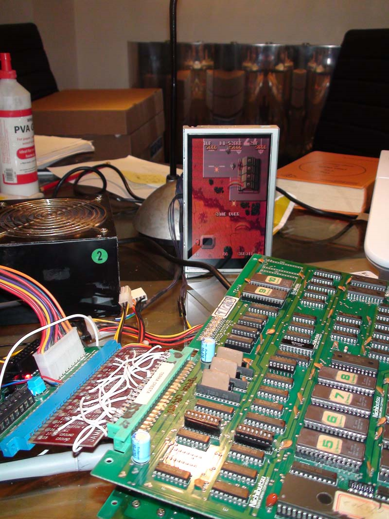
Another on my pile that has been wanting attention for a while. It is an original PCB and is the YM2203 version unfortunately, much prefer the YM3526 version with superior soundtrack.
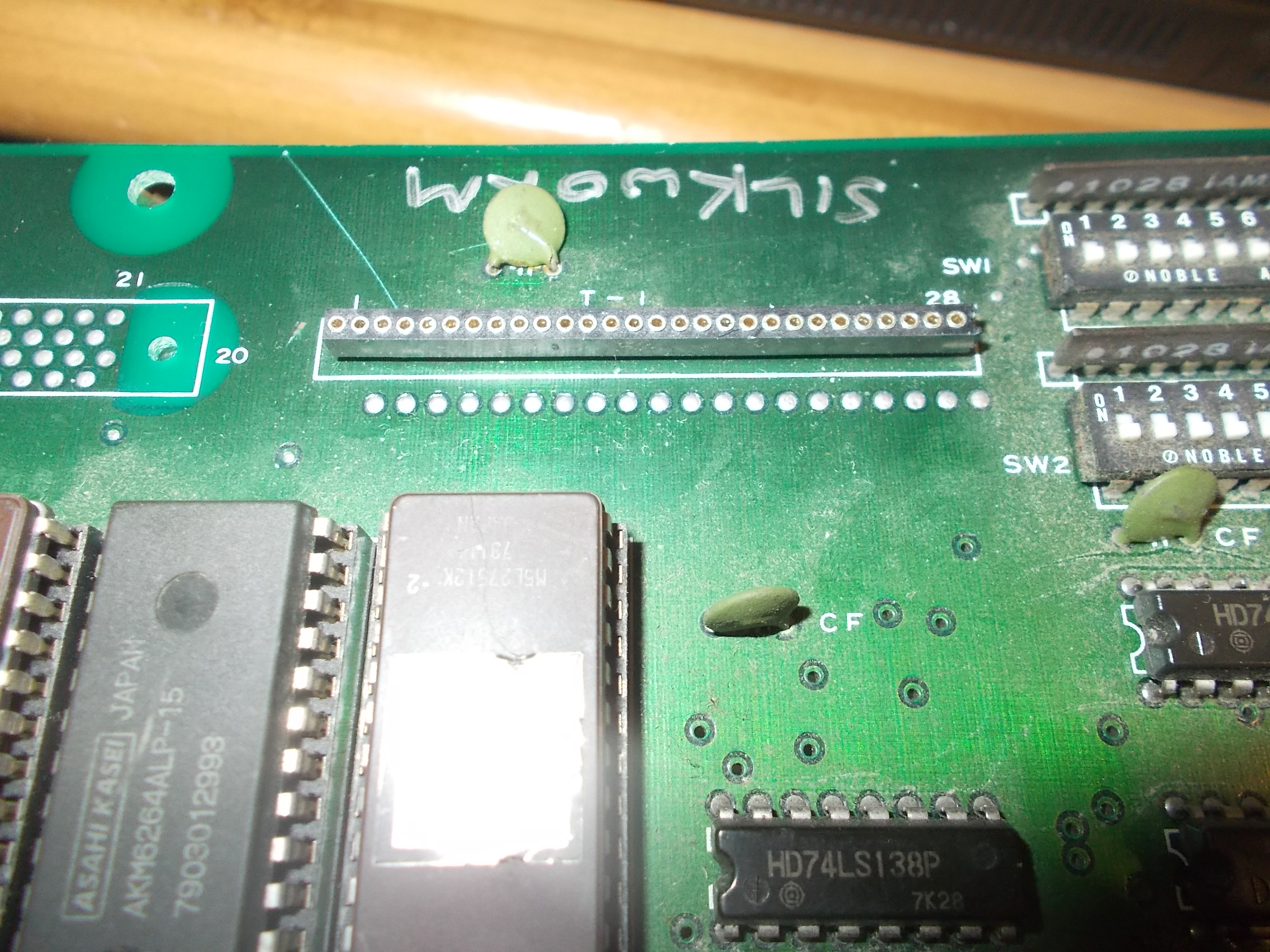
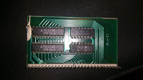
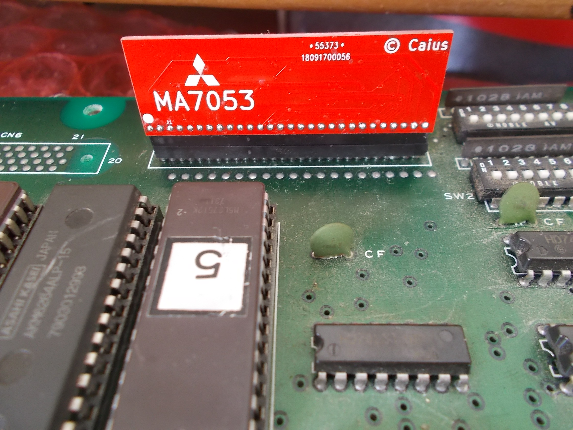
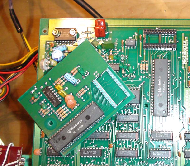
Which version you have is easily identified by a daughterboard (YM2203) on the underside of the PCB.
Symptoms
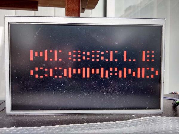
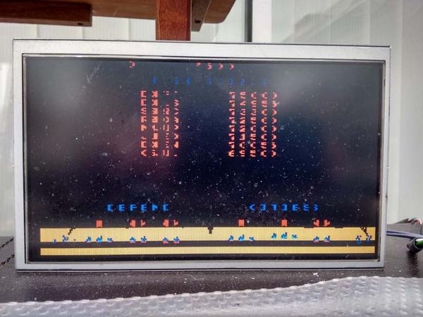
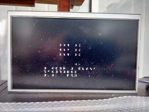
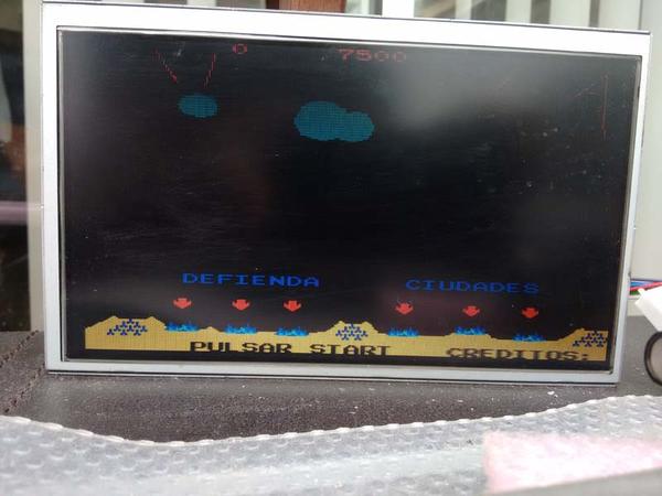
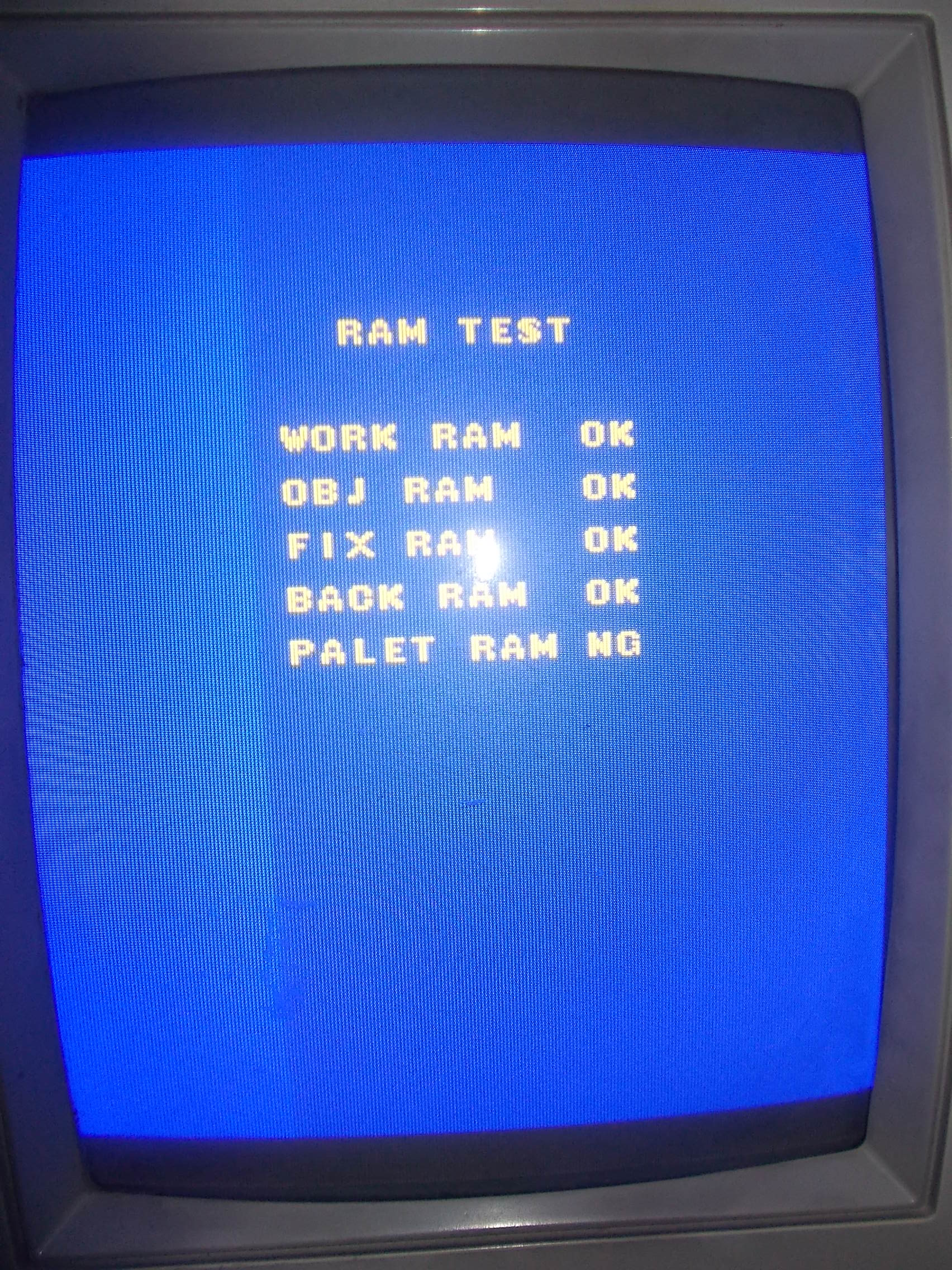
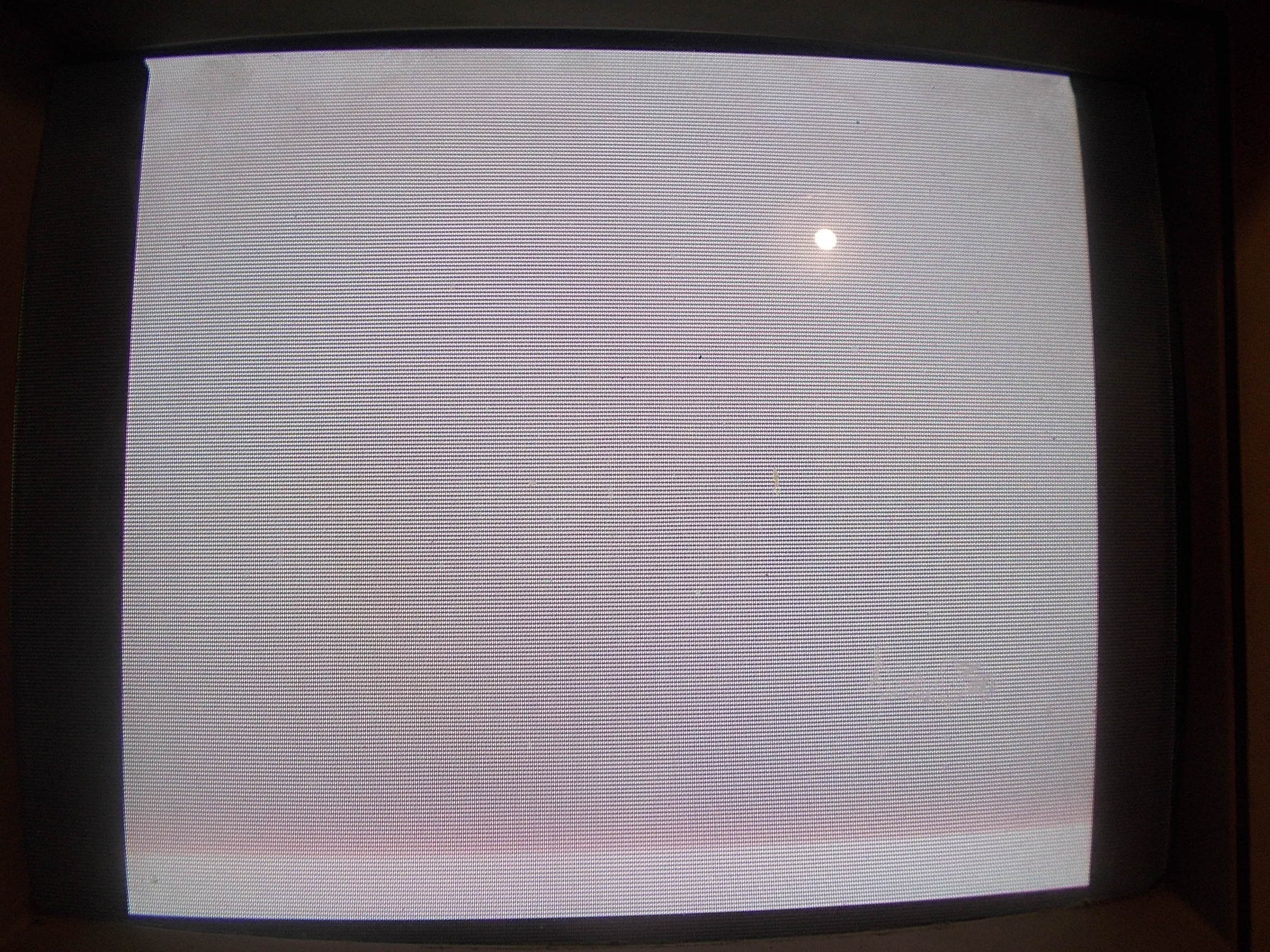
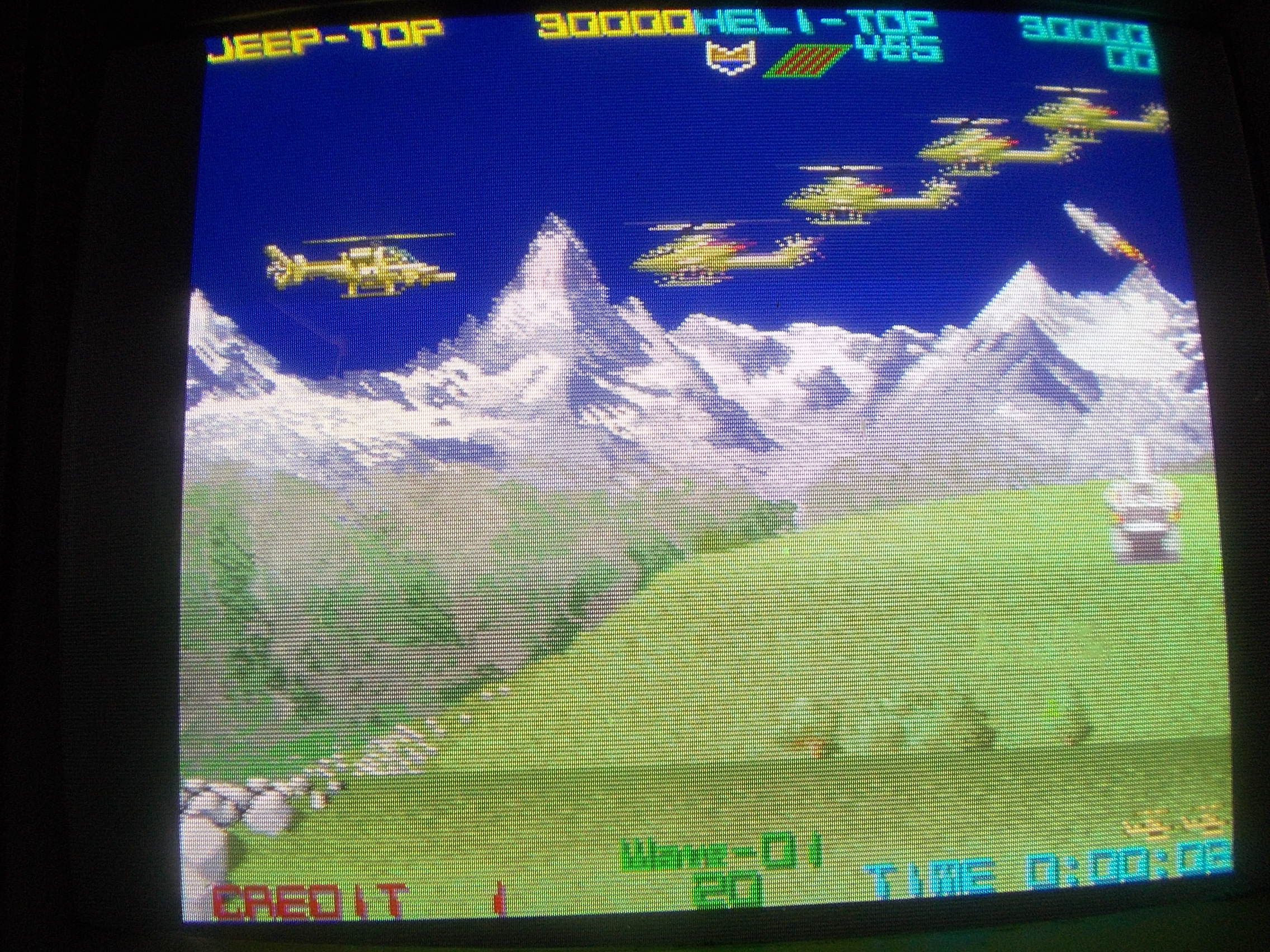
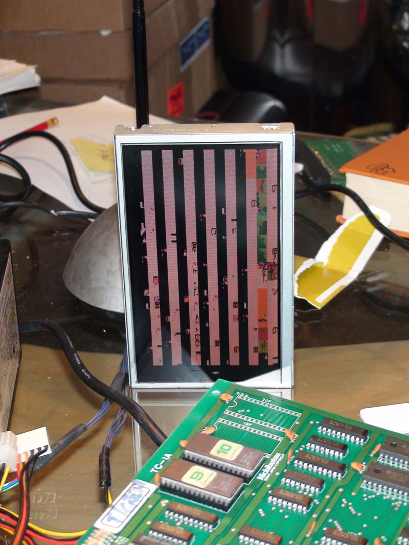
PCB will not run at all, all I get on the screen is static garbage which is always the same whenever I try to boot.
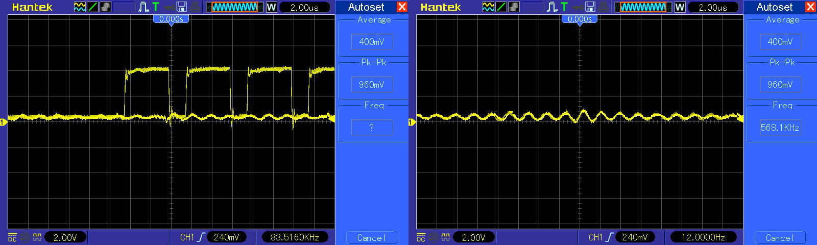
I started by looking at the clock circuit, I did this by checking the 68000 CPU’s Clock (CLK) pin which was pulsing as I expected, so the clock circuit must be good. The next thing to check was the RESET pin on the CPU which should have been HI, but it was LO and stayed LO, which mean’t no watchdog system was barking. Pin should have flipped to LO for a split second on boot and stayed on HI for an enabled CPU.
I probed further and checked the HALT pin on the CPU, which was LO, this told me there is a Bus error somewhere and the CPU has put its handbrake on.
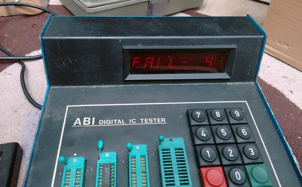
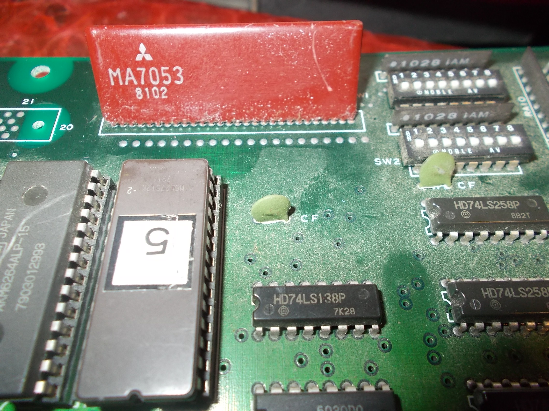
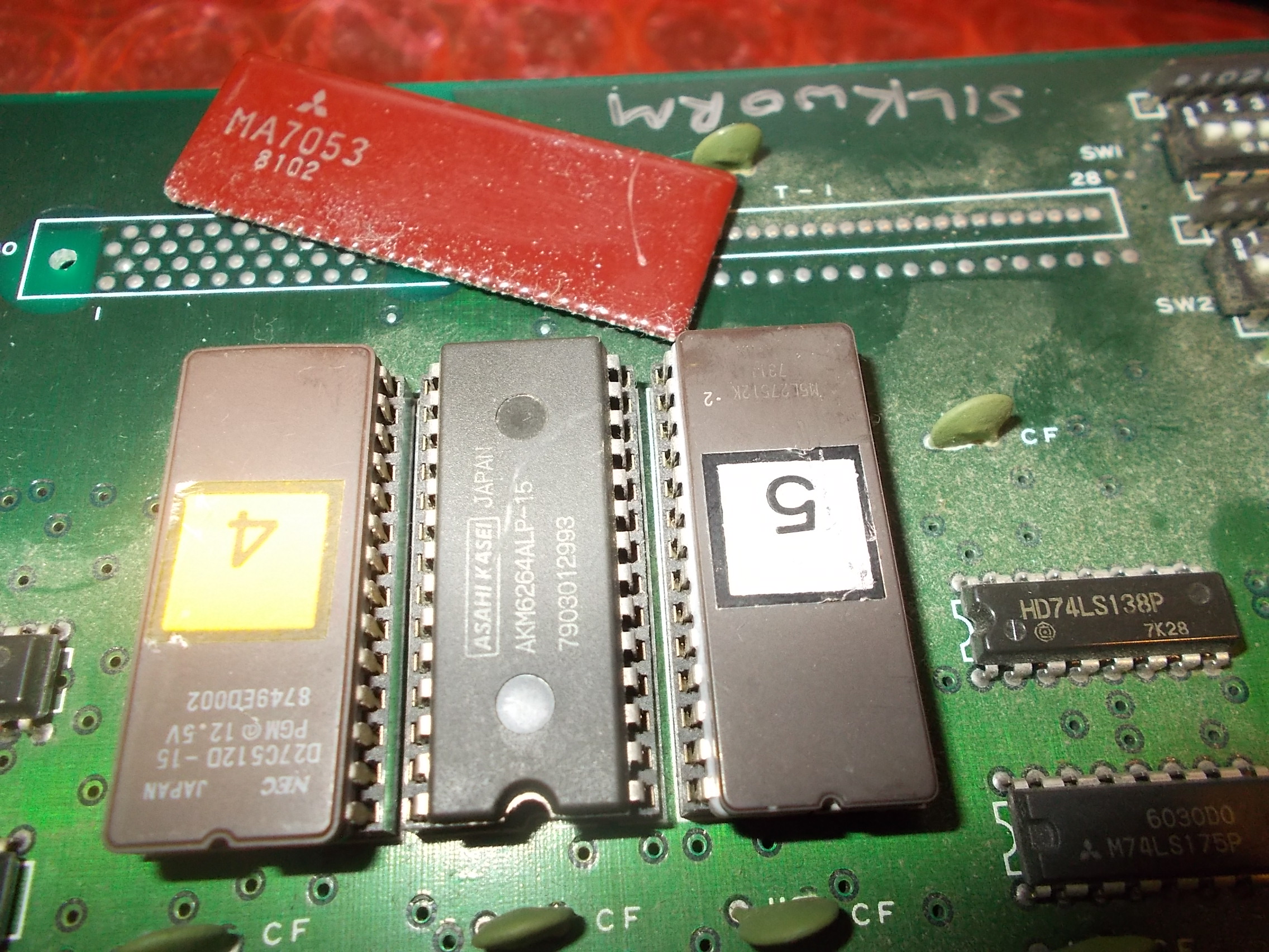
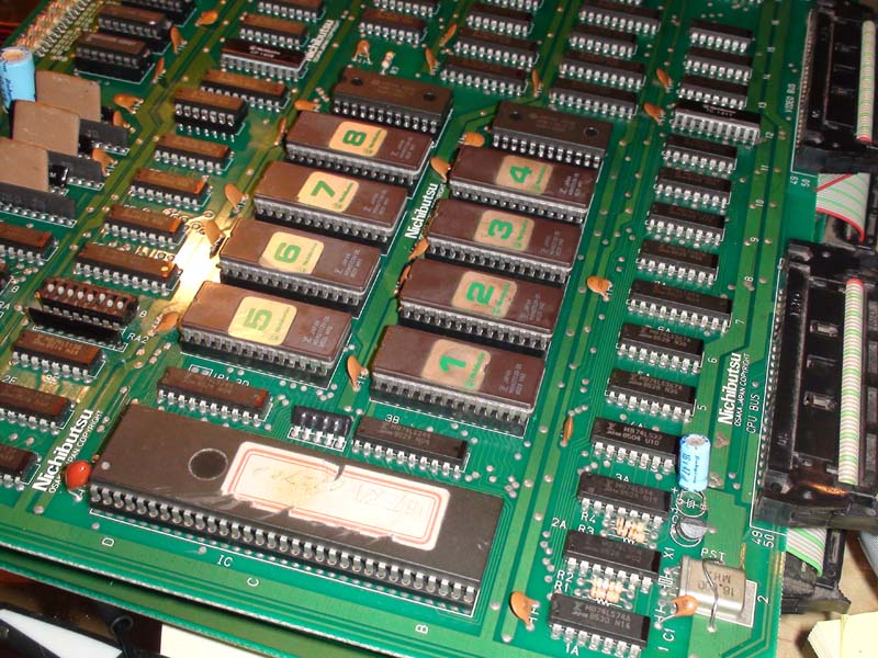
Next thing to do was verify the CPU program ROMS (1, 2, 3, 4, 5, 6, 7 & 8 ROMs) were good, as there is no point checking the PCB any further if it has nothing worth running. They all checked out good.
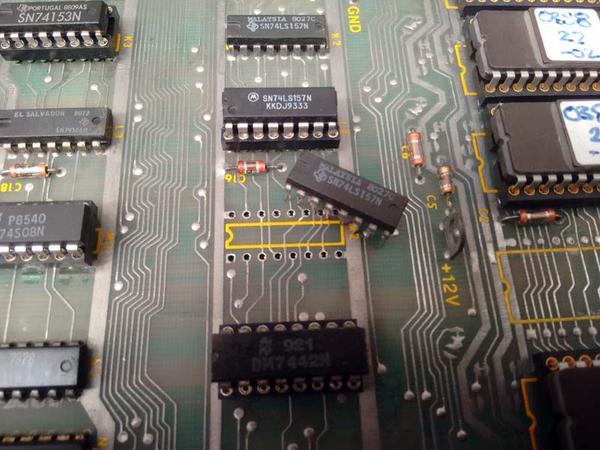
Next I checked the CPU buffers (74LS244), which were inactive as I expected but checked out good.
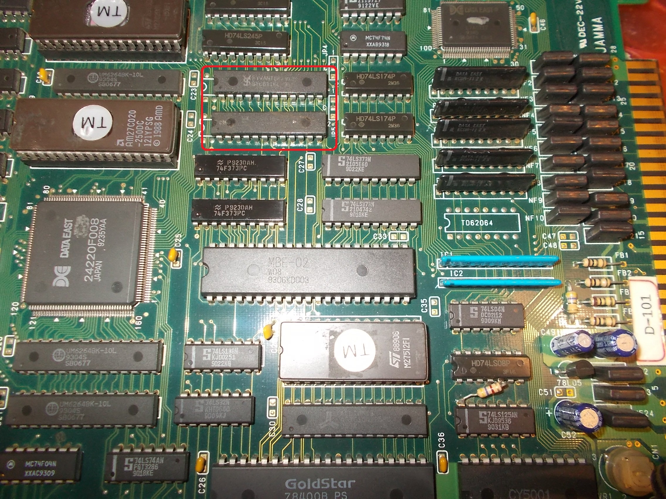
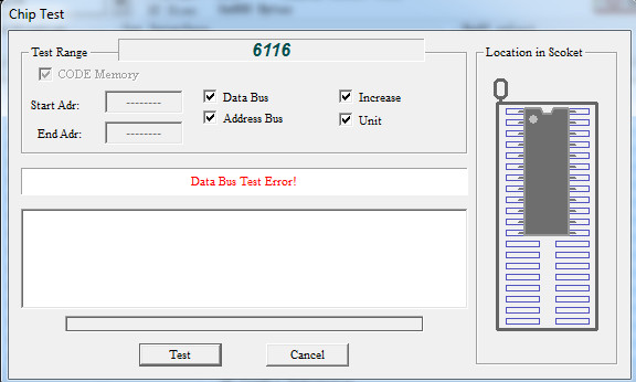
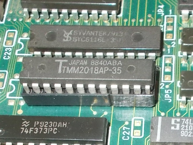
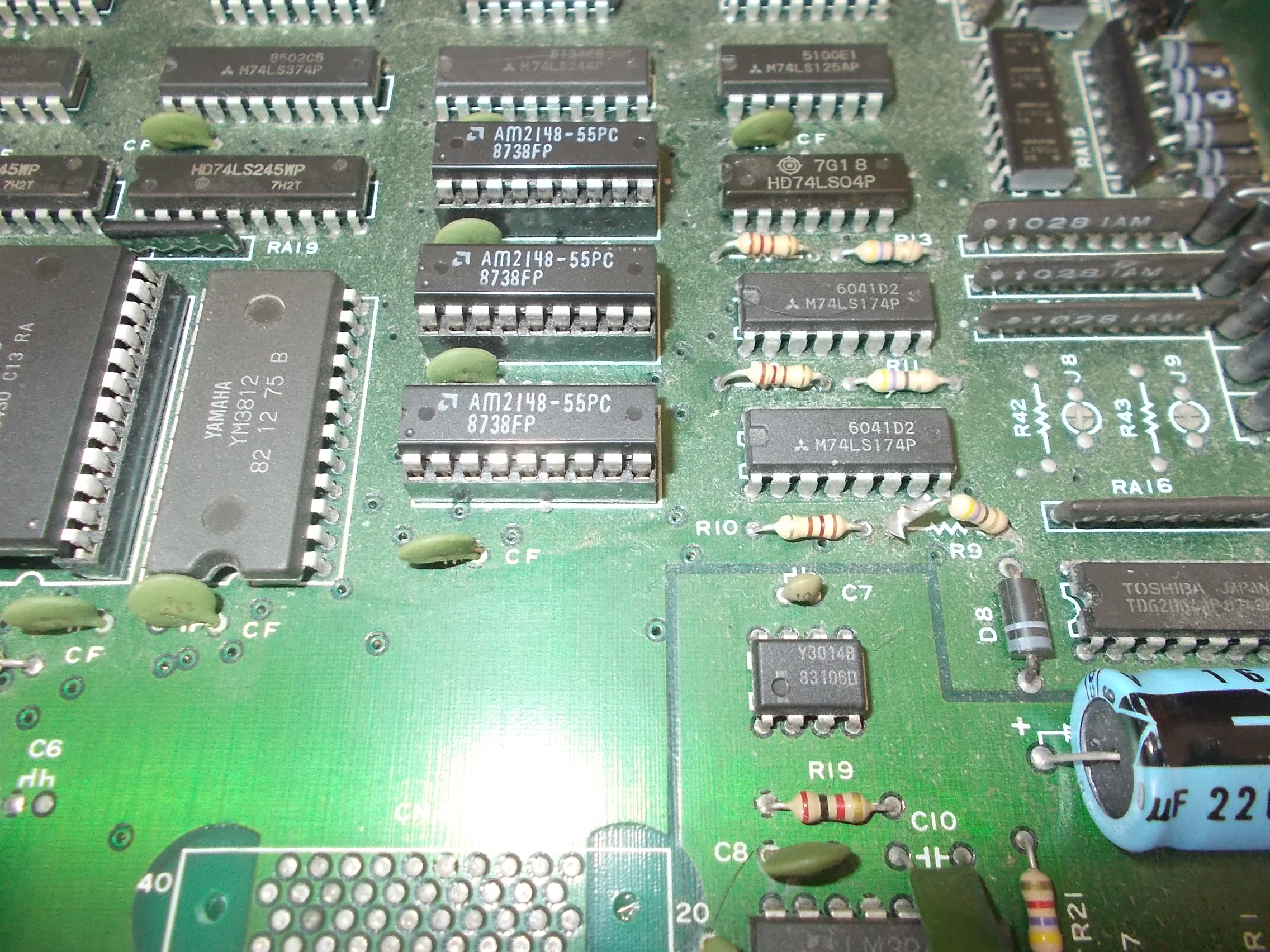
Ok I thought, must be the CPU RAM (6116) which is bad at locations 10b and 10d, I checked them but they were inactive as I expected, so desoldered them to test them. They both checked out good.
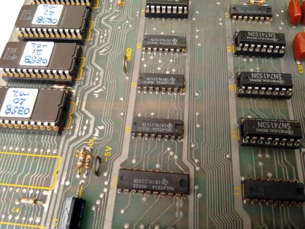
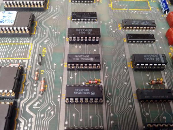
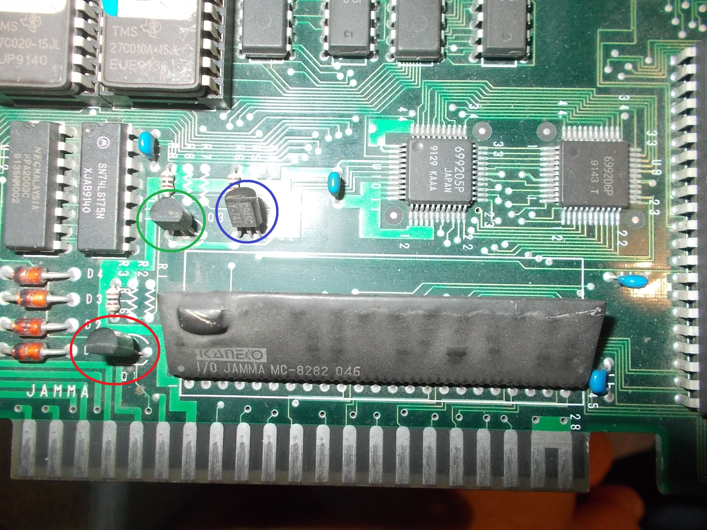
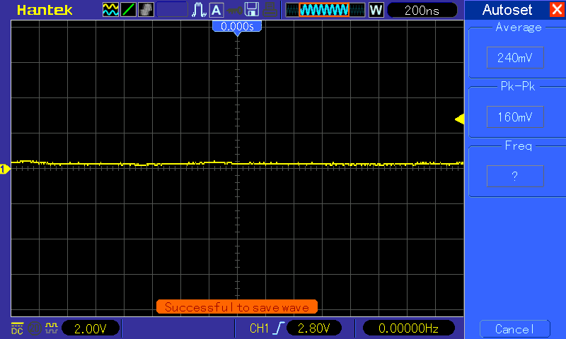
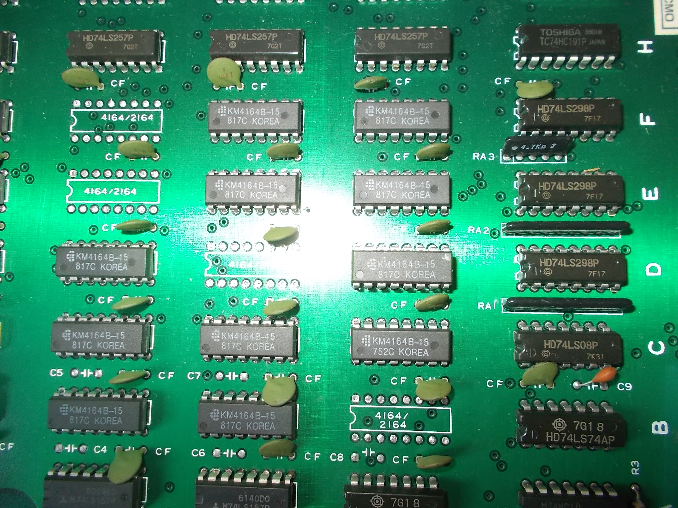
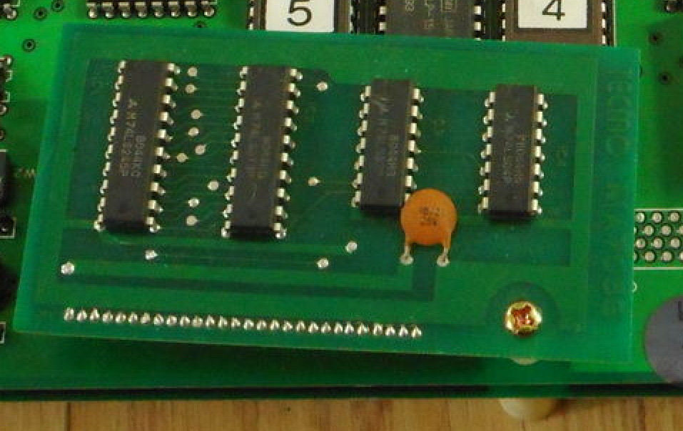
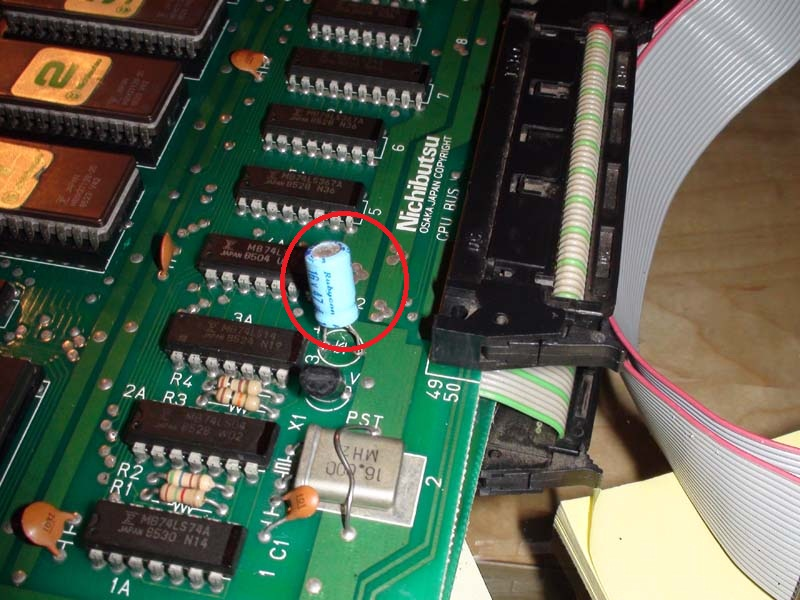
Hmm….at this point I had checked all components on the PCB which would stop the CPU running. I probed further and started to check the Caps. I found a Cap which when I checked both poles with my logic probe, it showed LO for both poles instead of LO (-) and HI(+) which I expected. This can only mean the Cap is shorted. I checked again with a Multimeter which confirmed this.
Off it came;
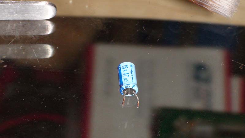
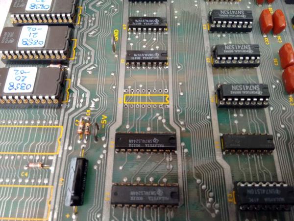
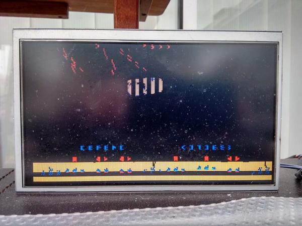
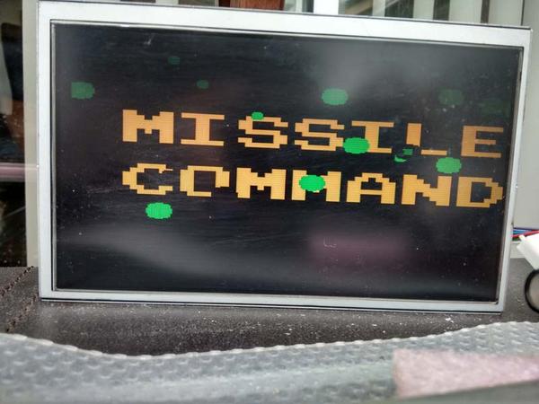
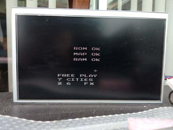
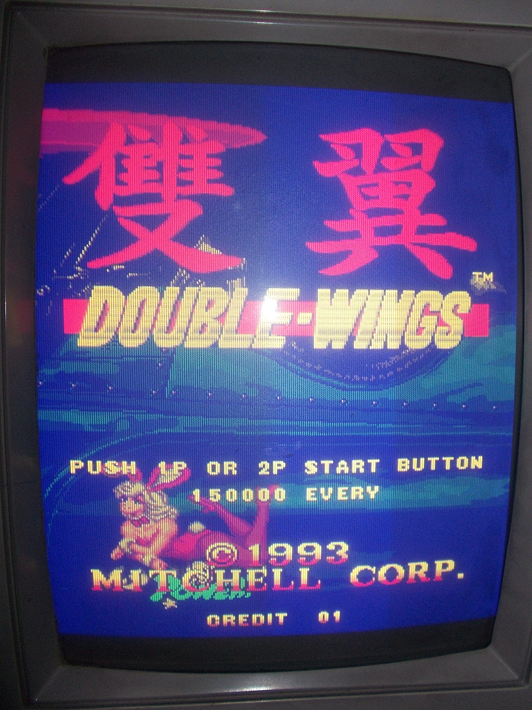
I soldered in a new Cap and the game came right up!
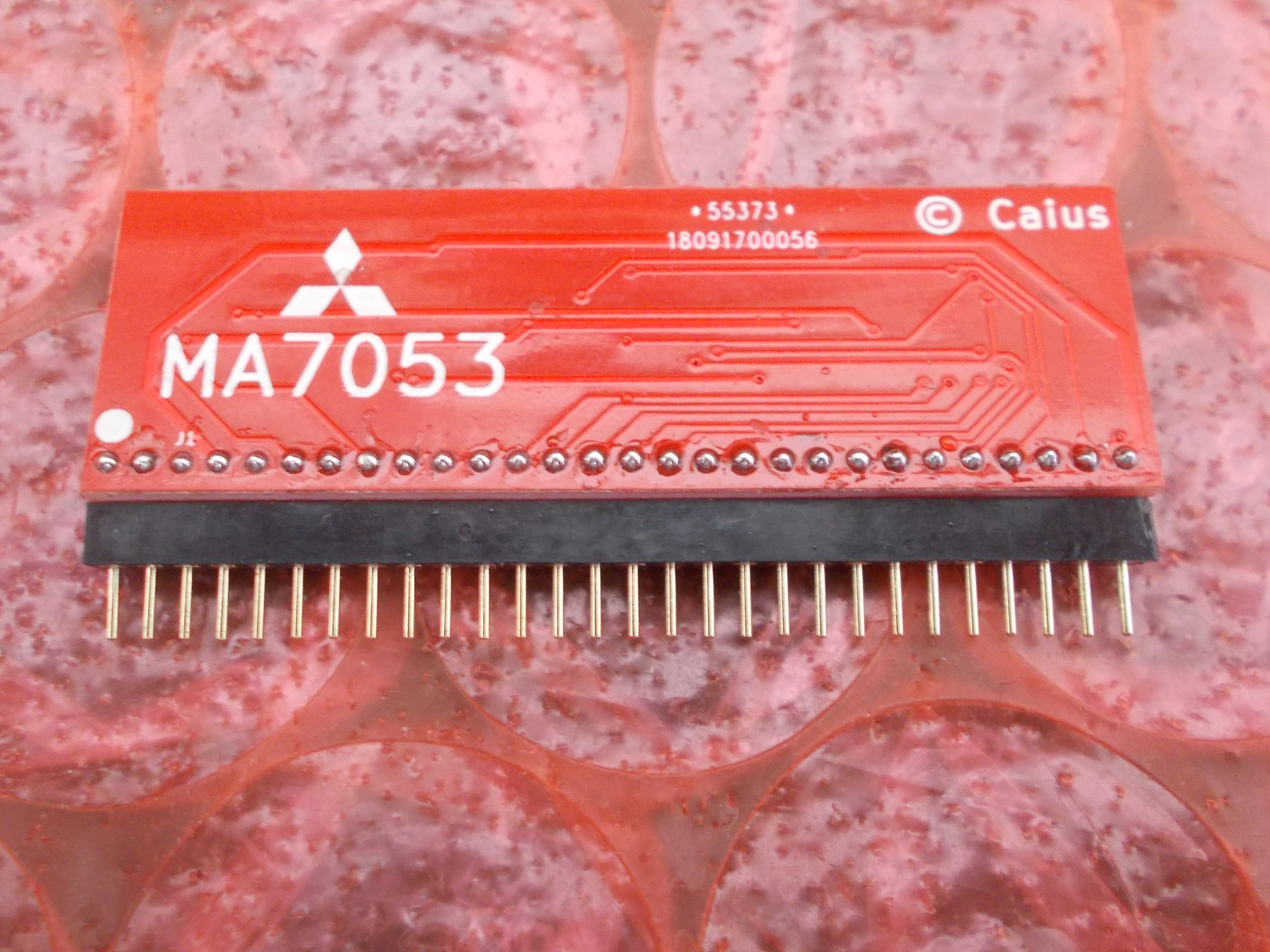
However, I was not finished yet! Time to convert this YM2203 PCB to a YM3626 version.
First, I removed the daughterboard, you can see the large YM2203 IC on the daughterboard with the Nichibutsu markings on it. The other large Nichibutsu on the PCB is the Z80A for the games sound and soundtrack. Was this an attempt by Nichibutsu to disguise these non-custom components?
Then we need to reburn ROMs 11(15b) & 12(17b) with the sound code from the YM3526 version of the game from MAME. Also, we need to introduce ROM 13(18b).
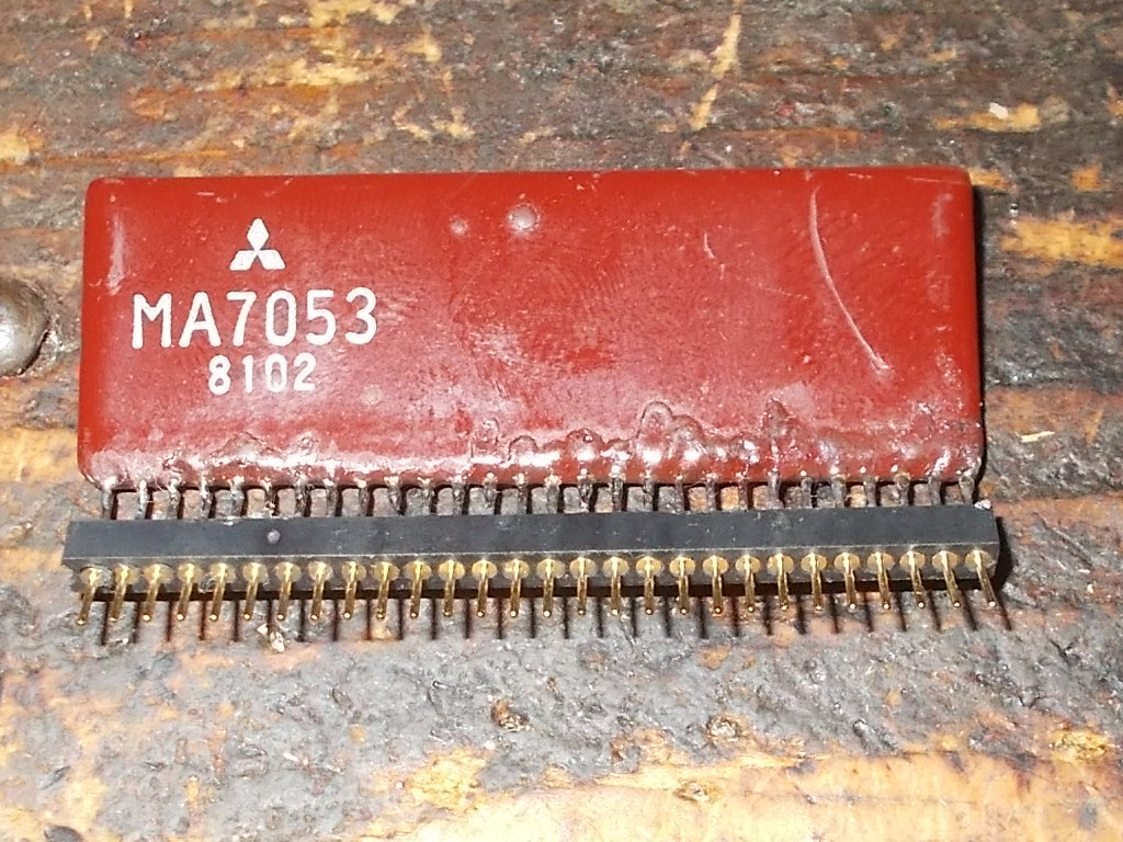
Next, seat the YM3526 IC where the daughterboard once was;
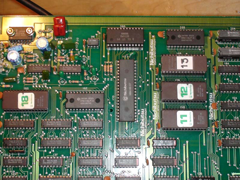
Job done!