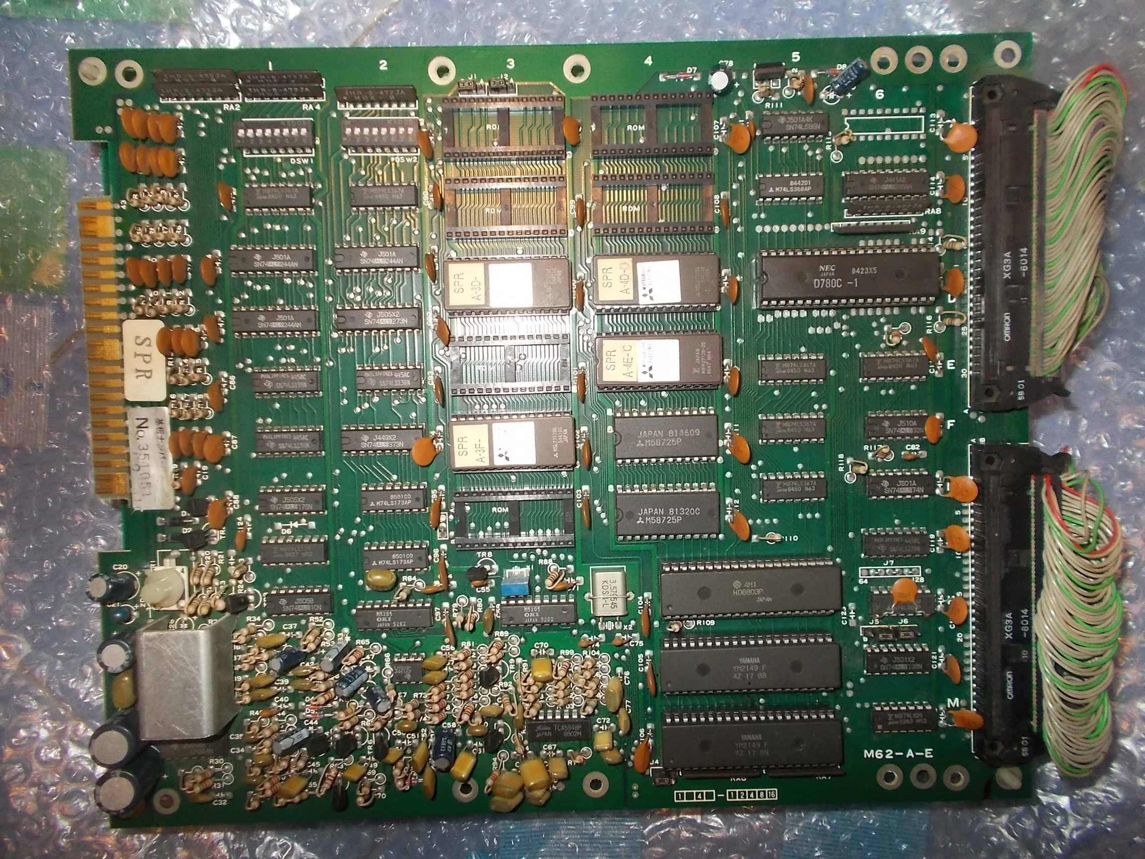
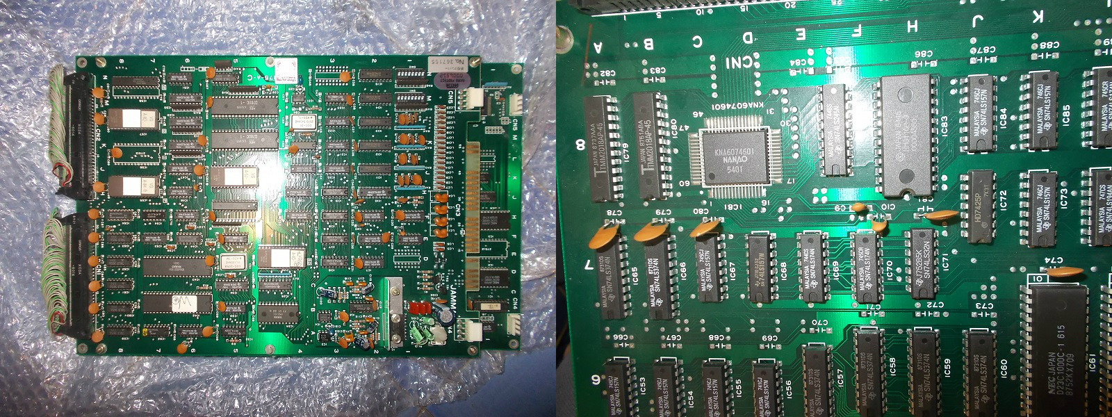
I received for repair a quite rare original Spelunker PCB (on Irem M62 hardware).Board is a three stack one made of a top board (which carries most of sound hardware) :
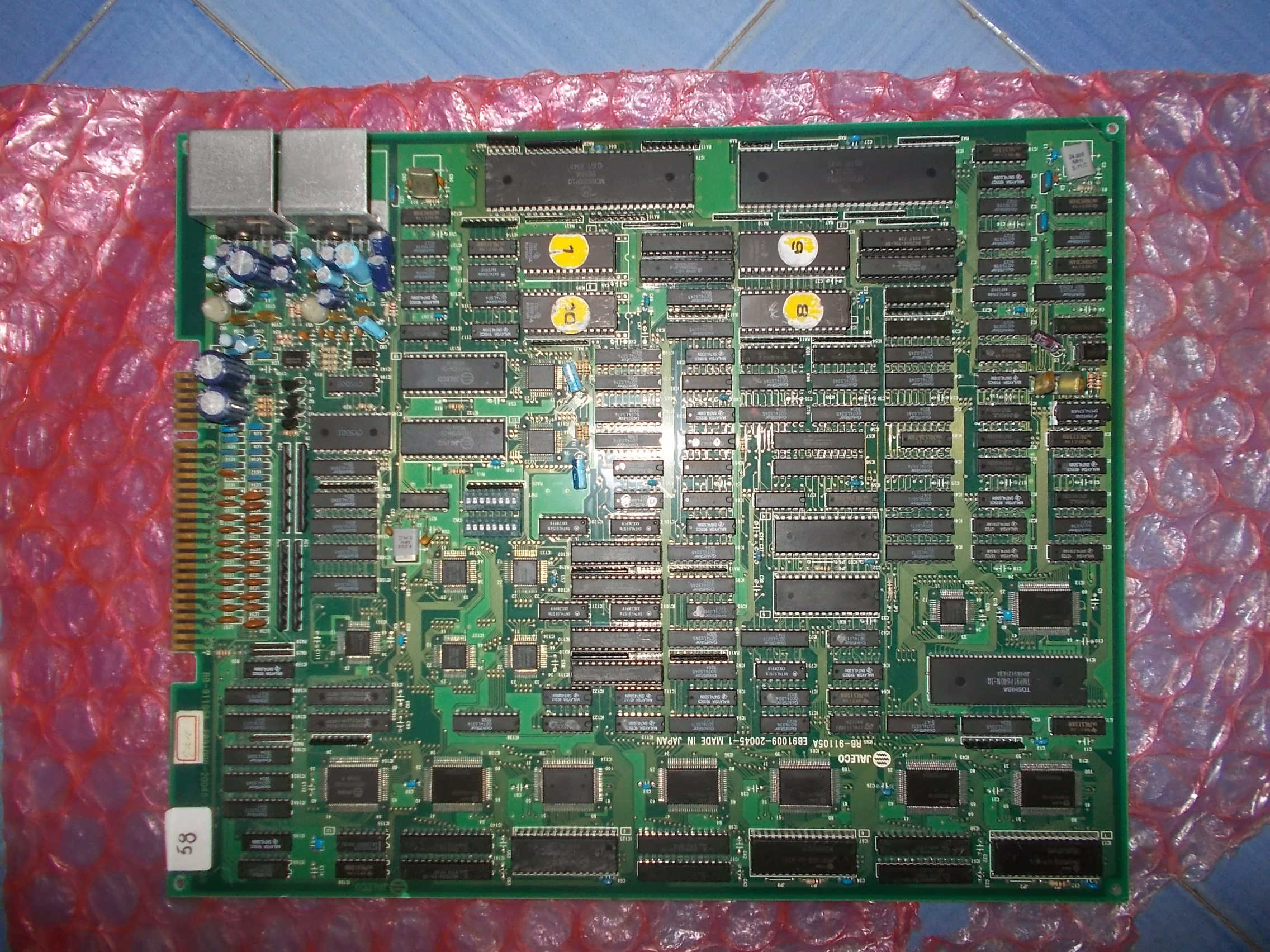
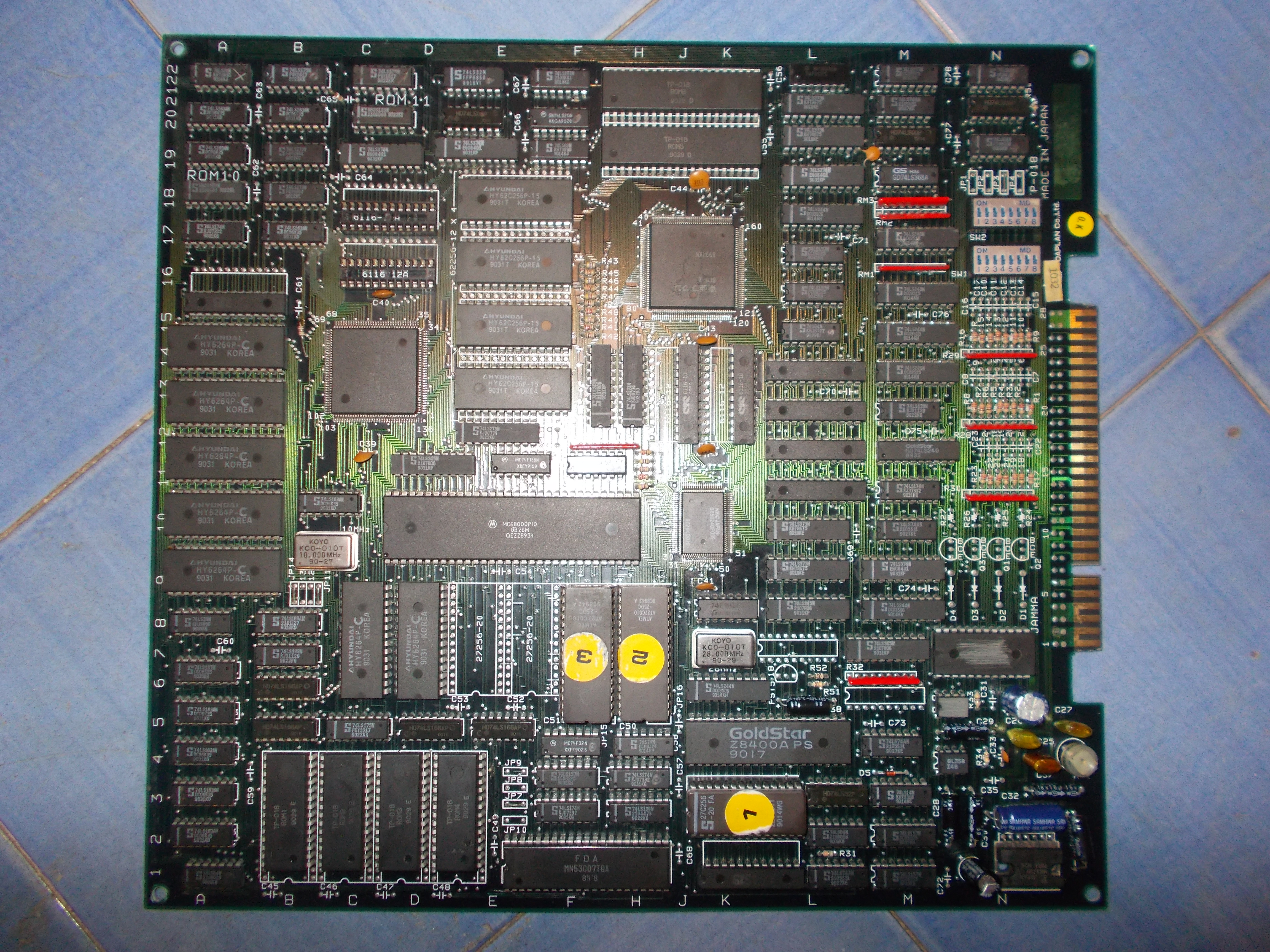
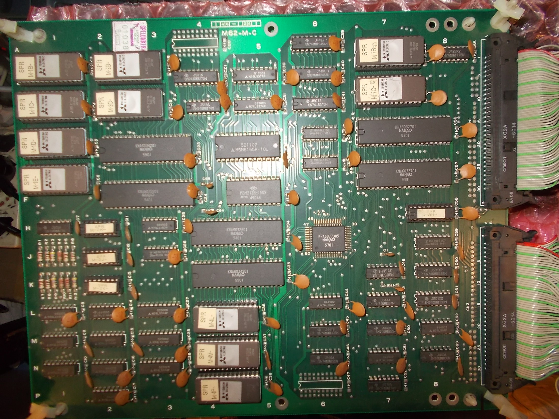
A middle CPU board (specific for each M62 game) :
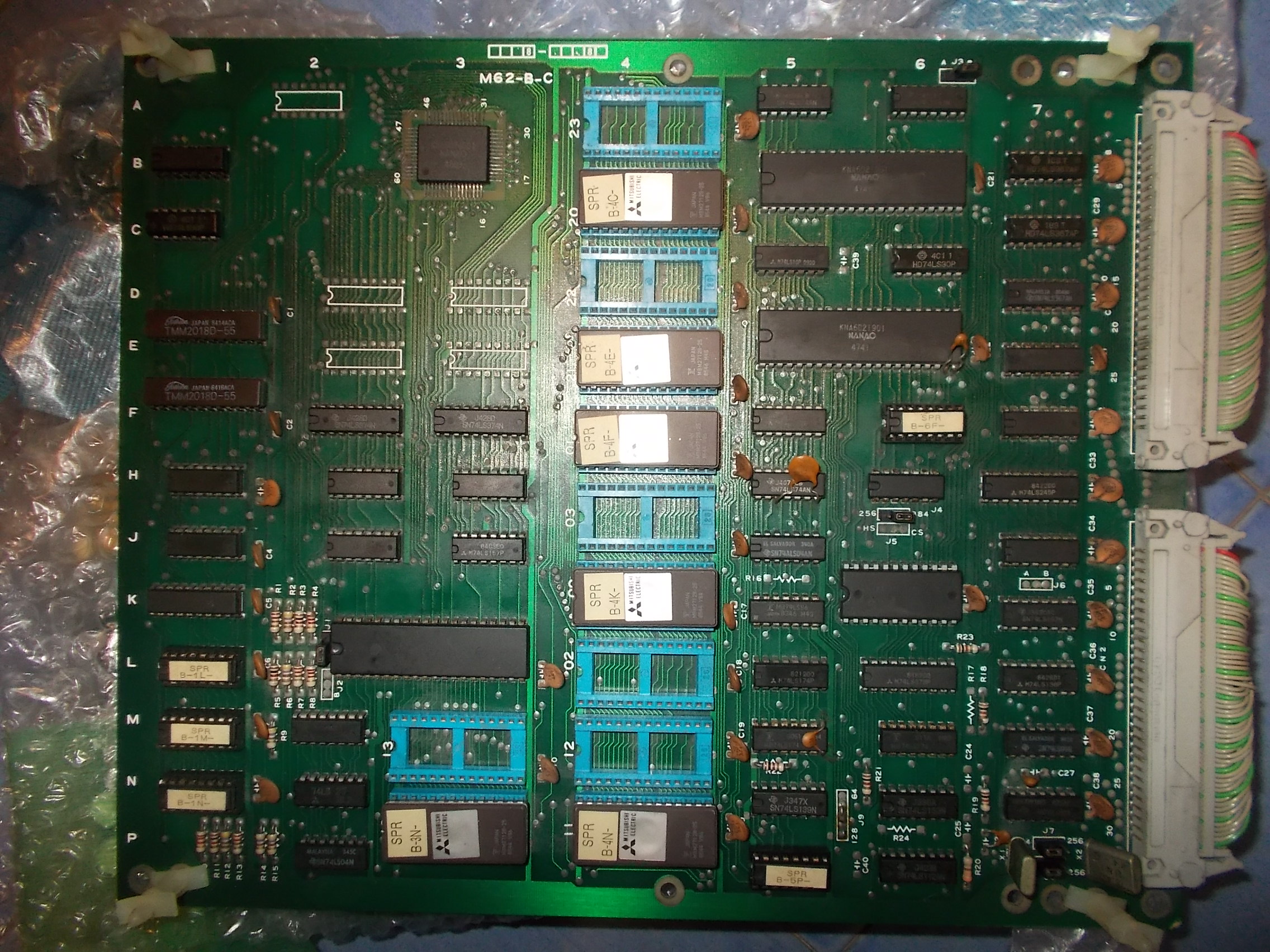
And a bottom VIDEO board :
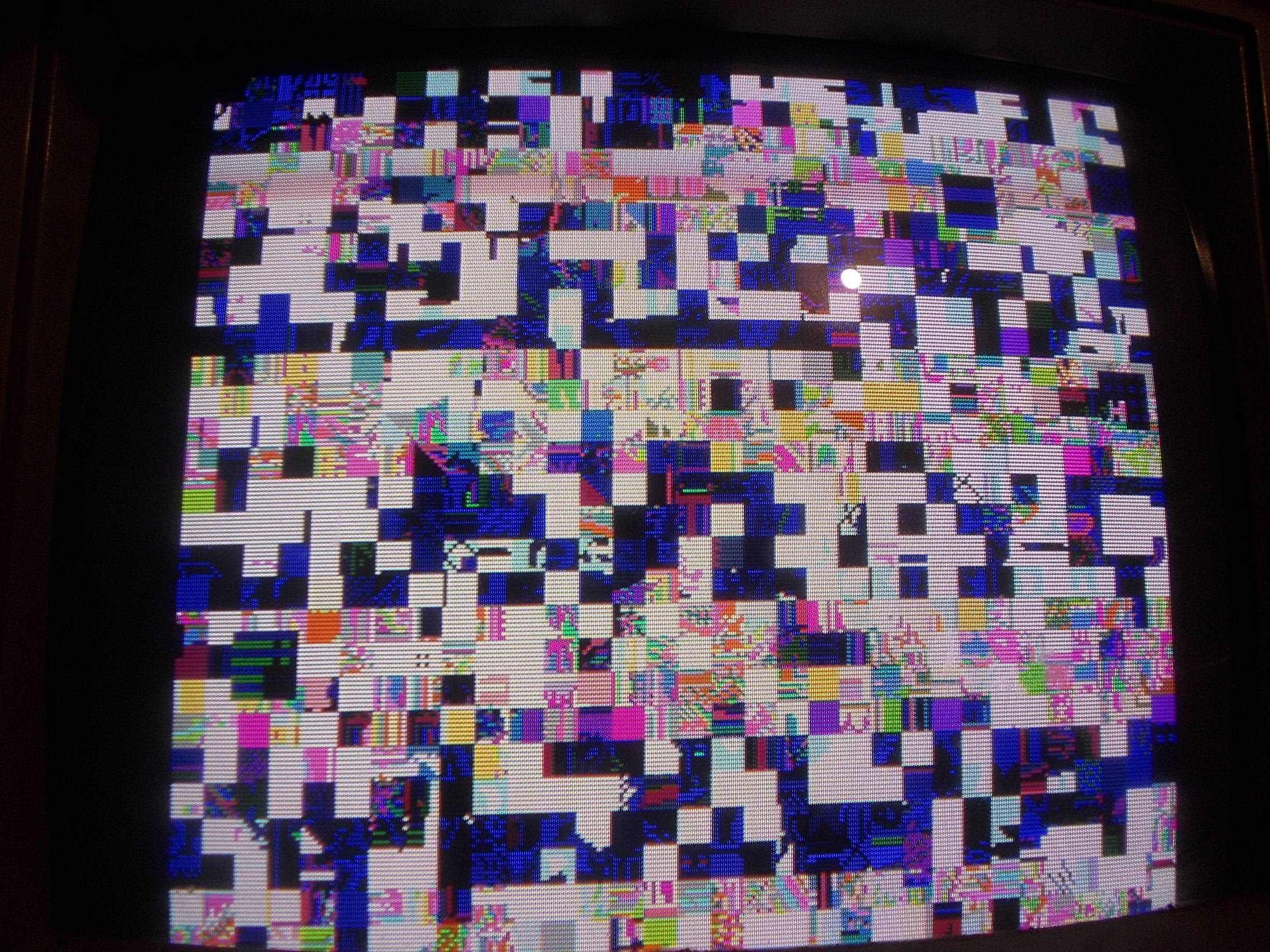
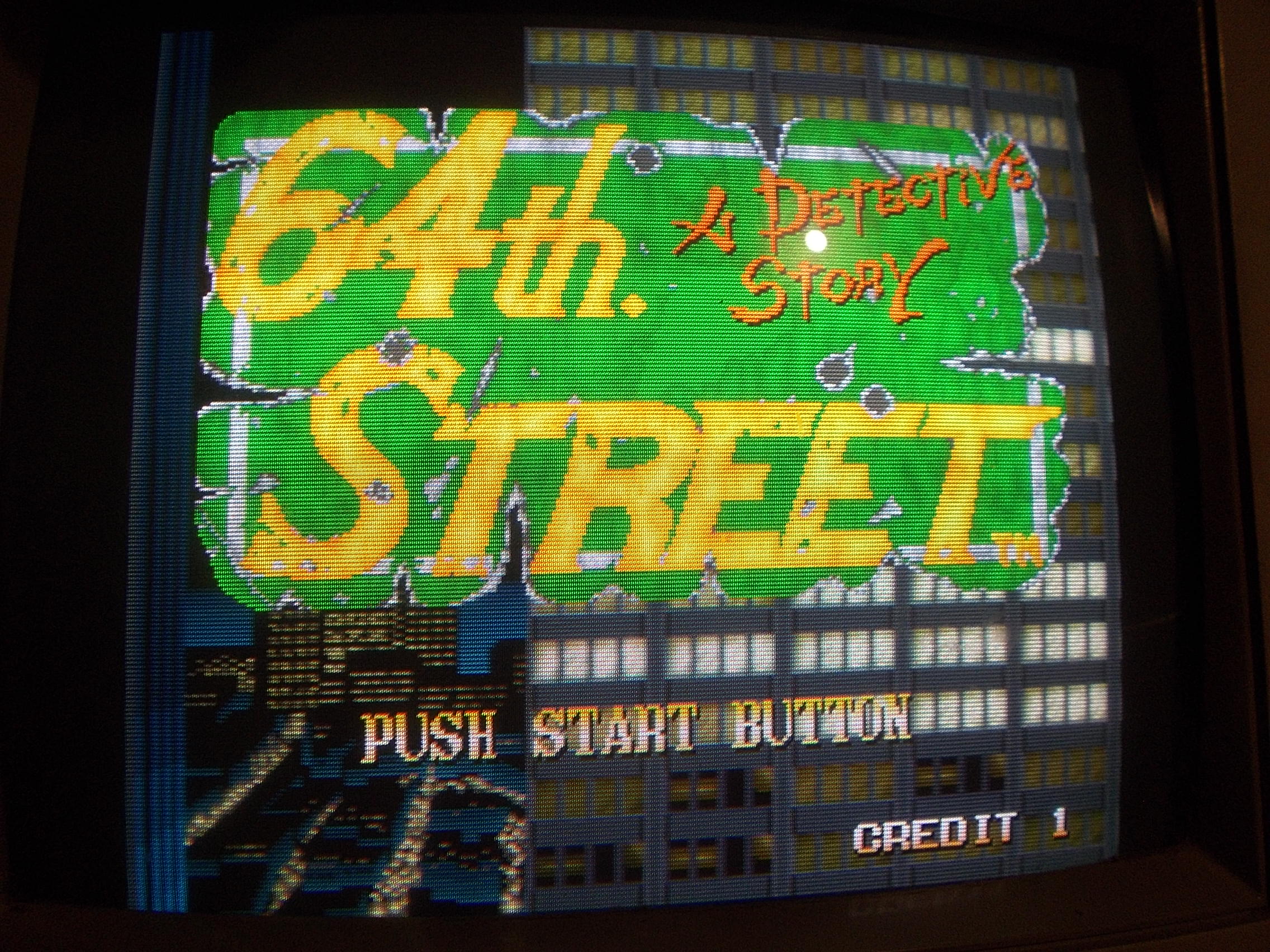
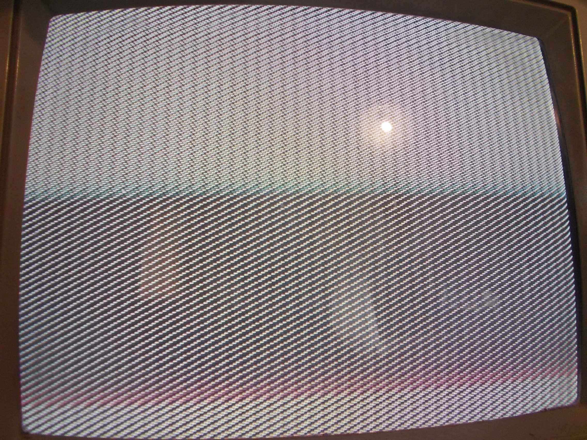
The PCB had severe GFX faults, the sprites were only lines vertically stretched all over the screen:
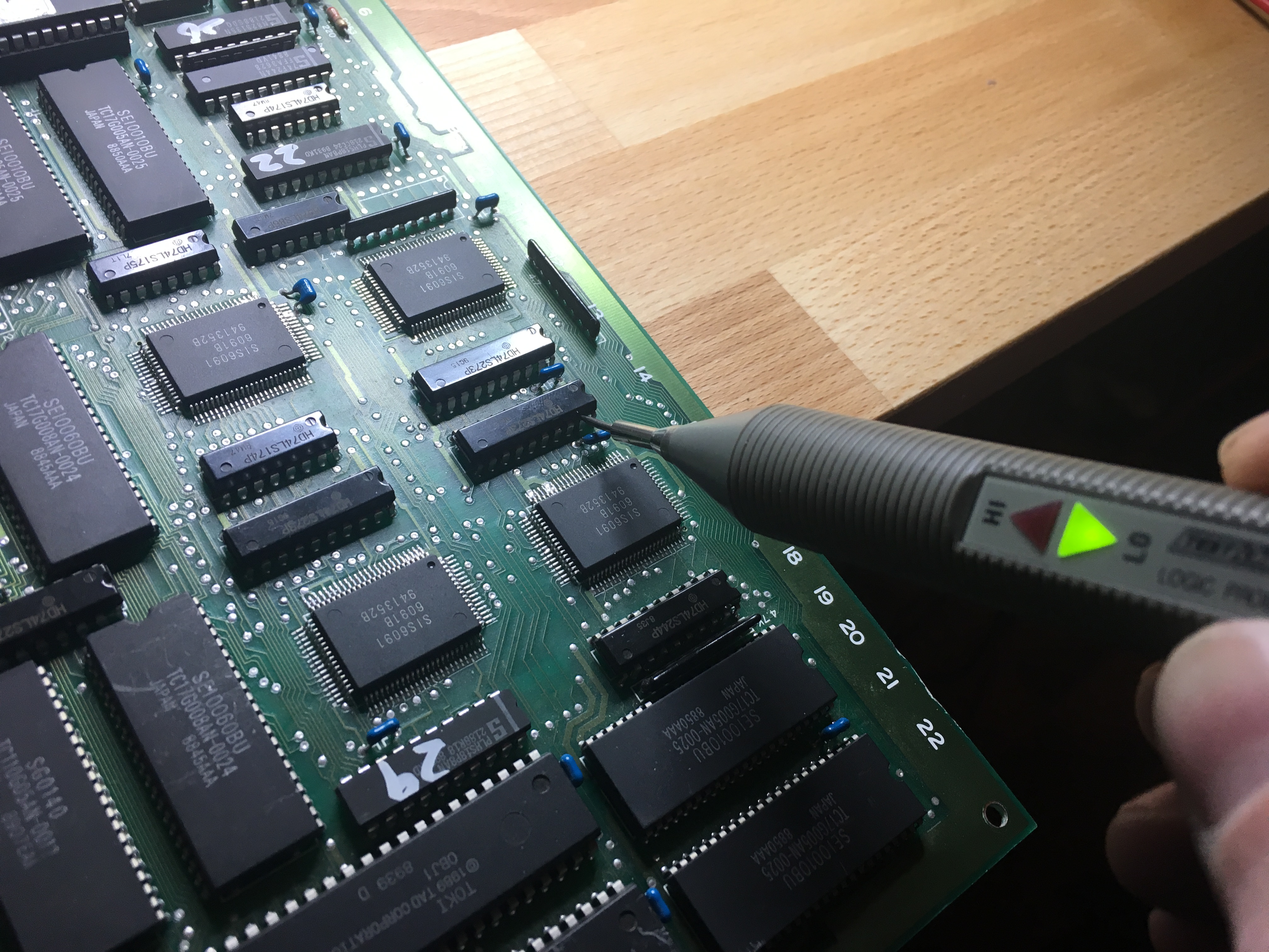
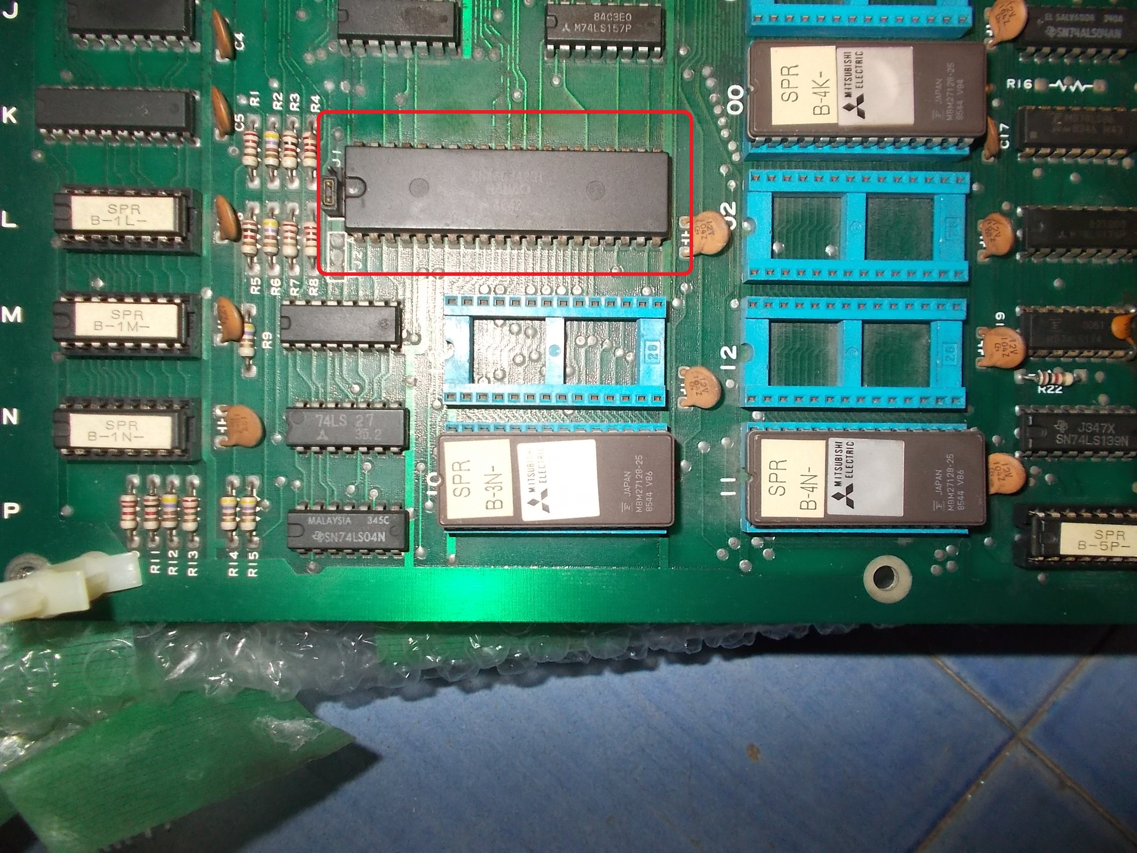
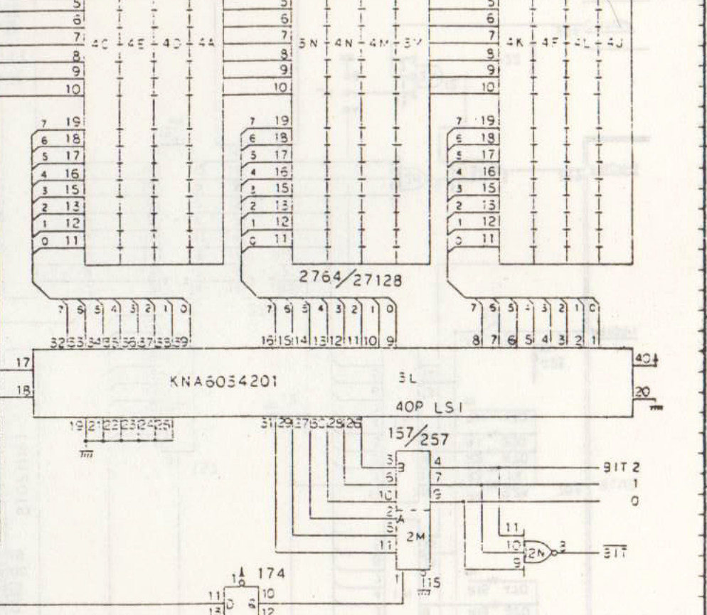
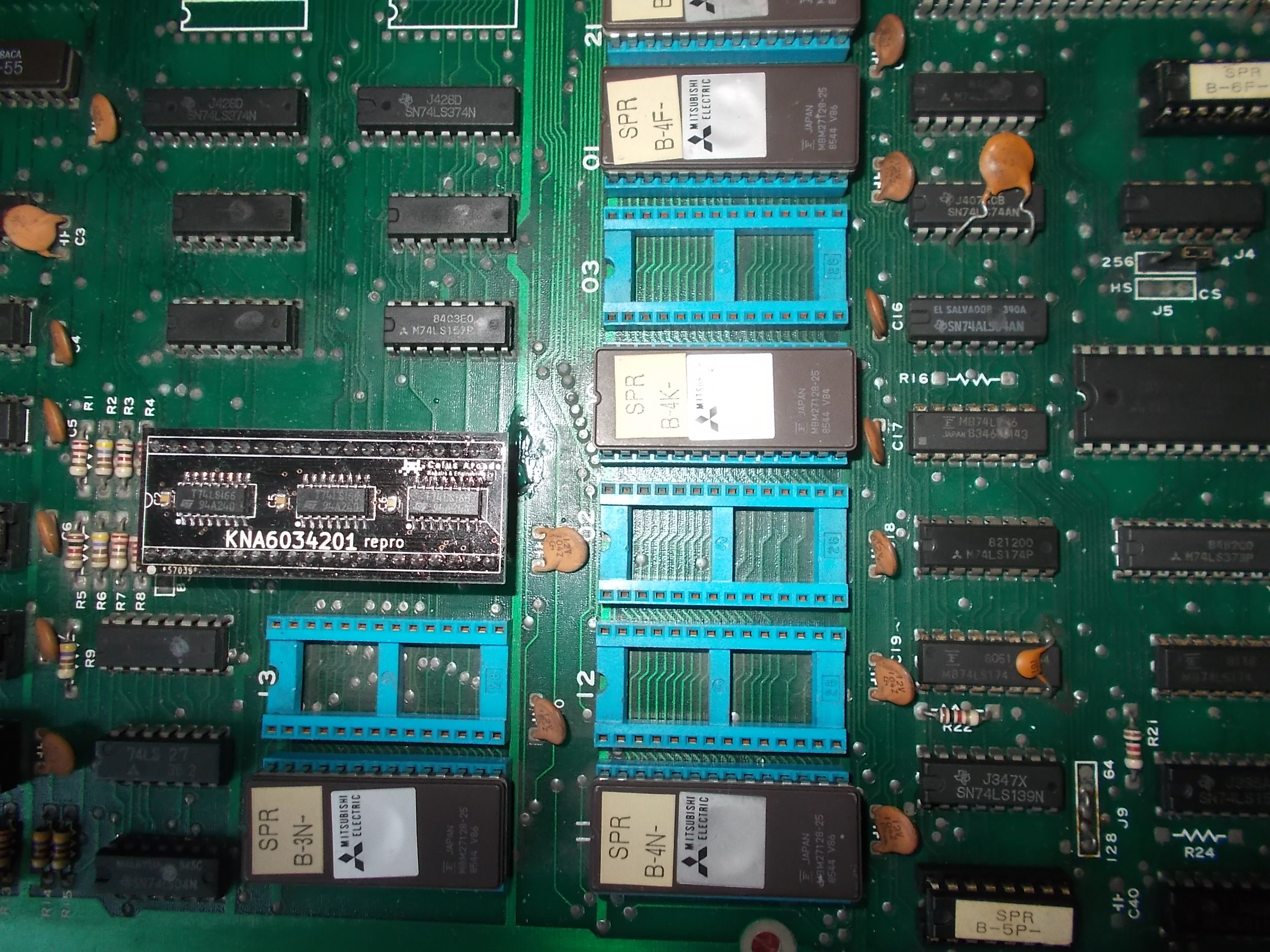
All the sprites circuit lies on bottom VIDEO board which is the same for all games that run on M62 hardware.Looking at Kung-Fu Master schematics I could figure out that data bits from sprite ROMs are fed into the custom marked ‘KNA6034201’ :
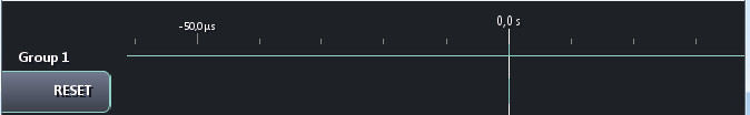
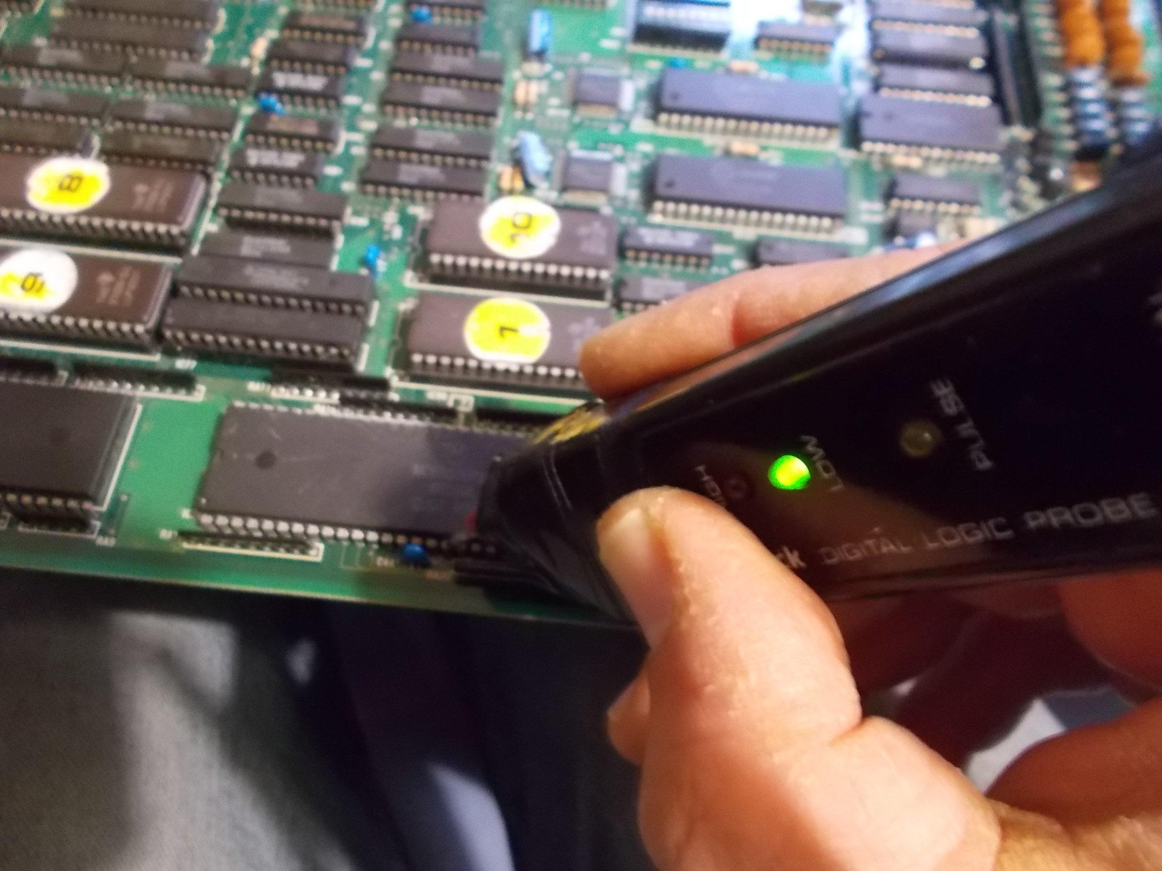
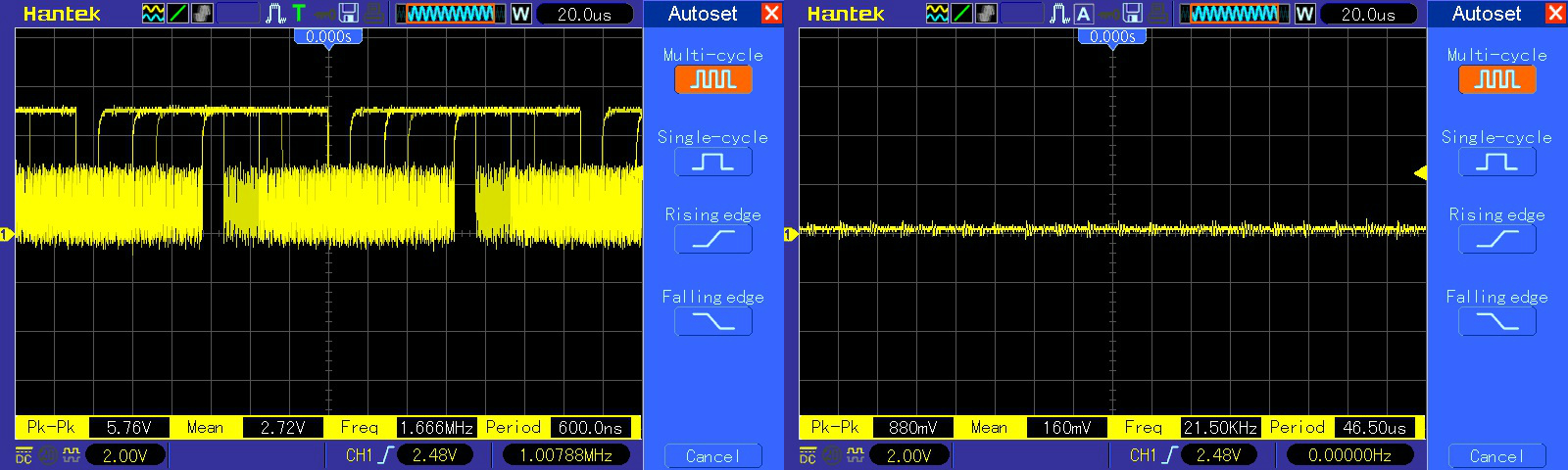
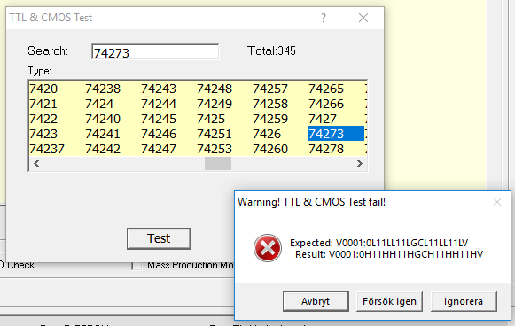
The inputs were all active but most of outputs floating:
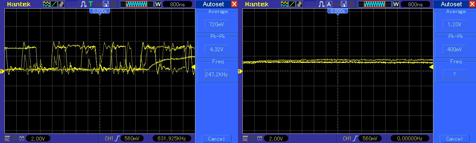
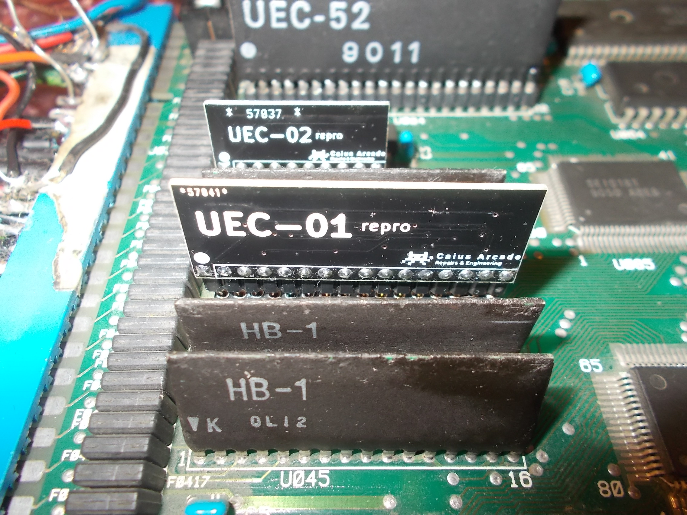
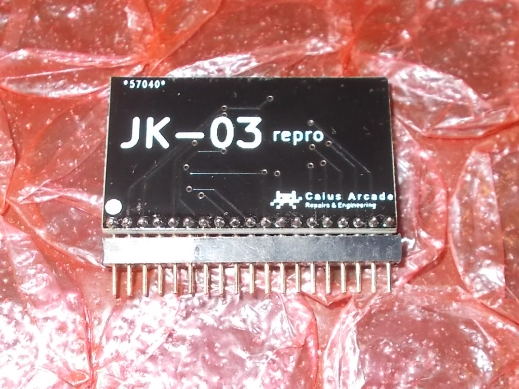
So the custom was most likely internally faulty.Luckily I have done a reproduction of this component some time ago.You can think of it like a 24-bit parallel to serial shift register:
I removed the custom and installed the reproduction:
The sprites were back but not perfectly as they were lacking of lines and misplaced too:
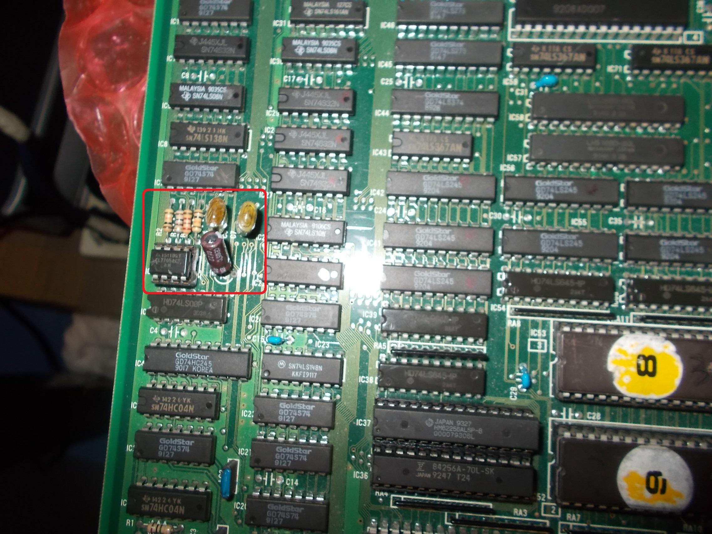
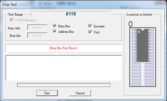
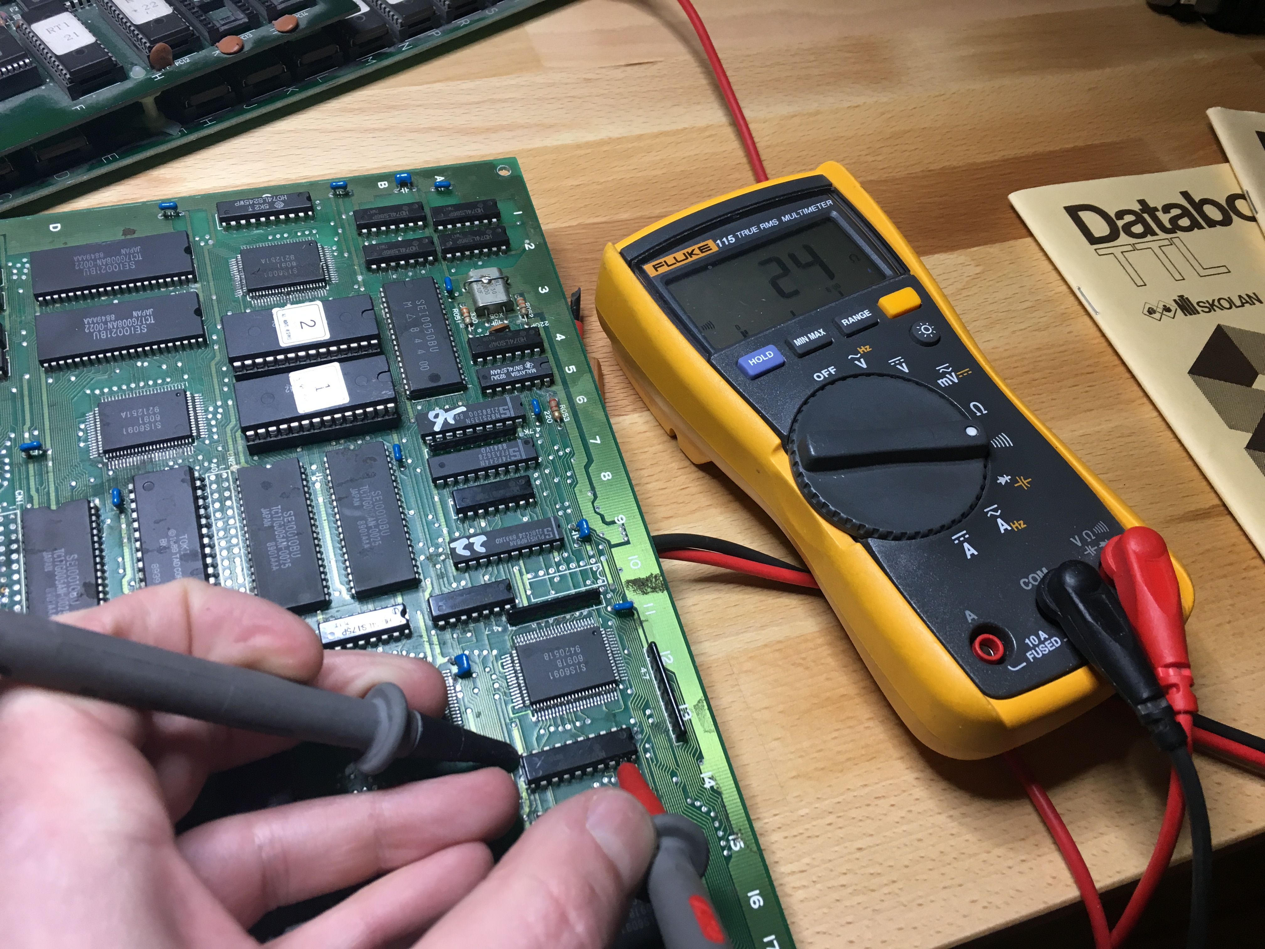
The sprite line buffer consists in two 2k x 8-bit static RAMs (Toshiba TMM2018 used here) :
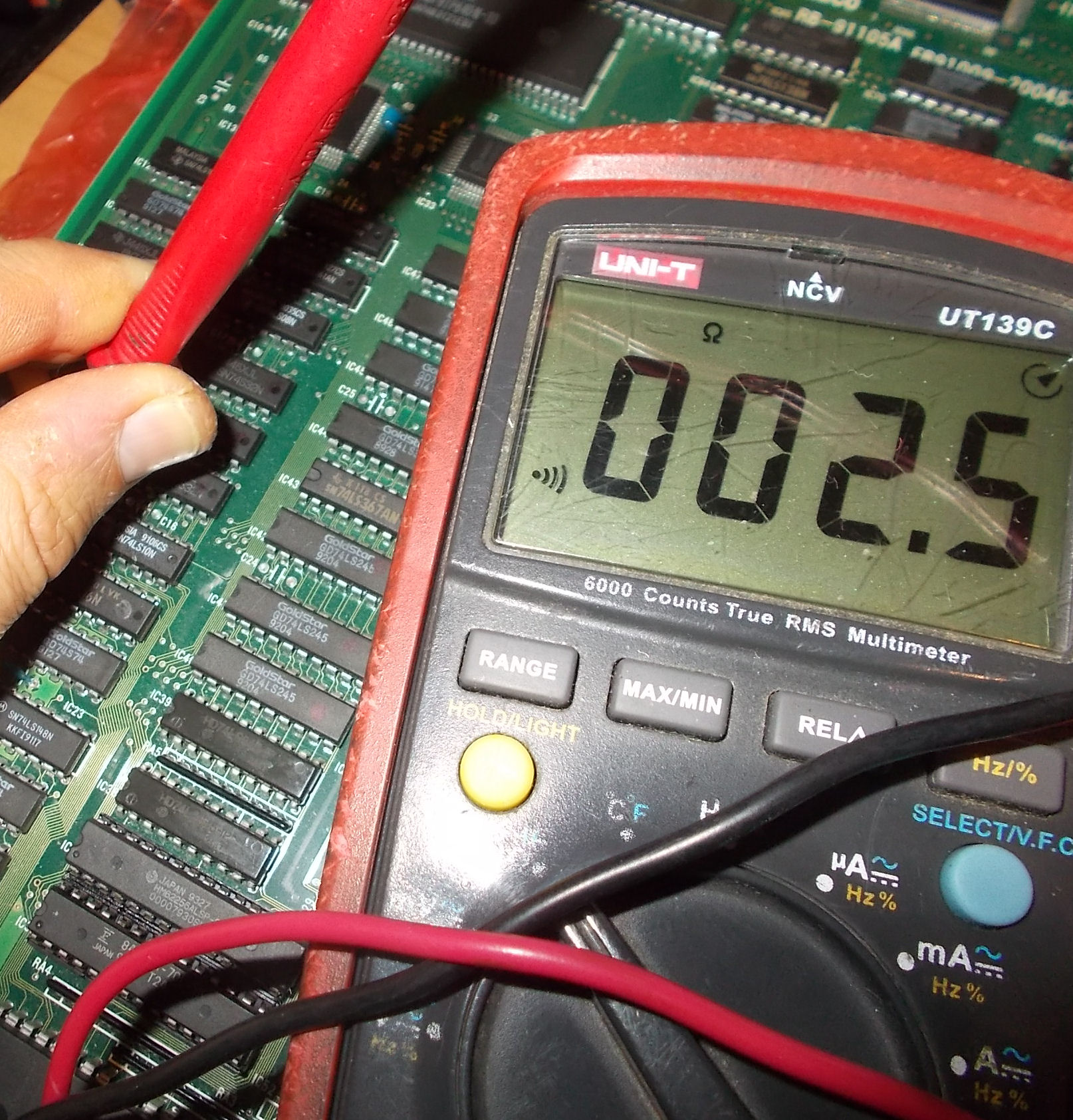
Probing them revealed on both a floating address line (pin 1, A7) :
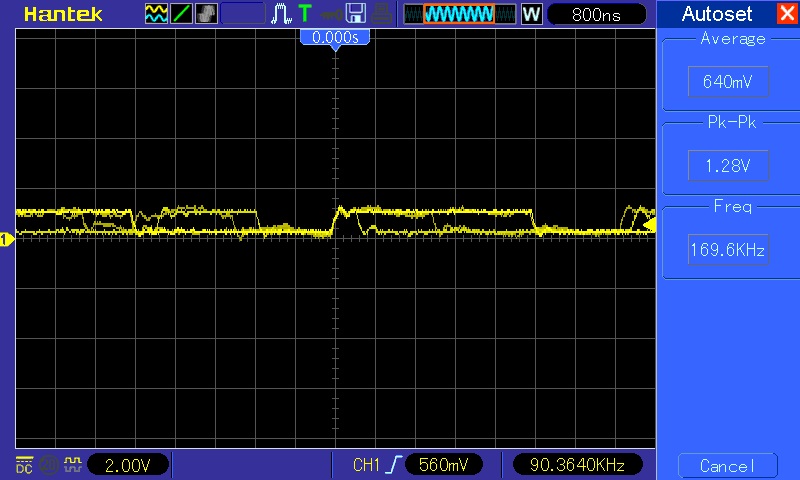
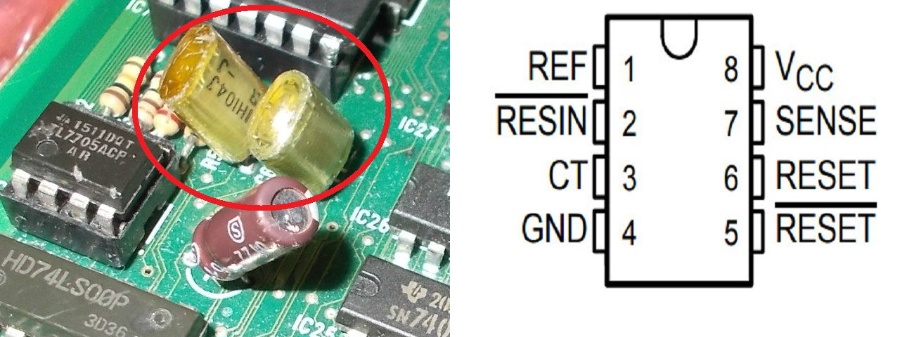
Address lines are generated by the surface mounted custom ‘KNA6074601’ :
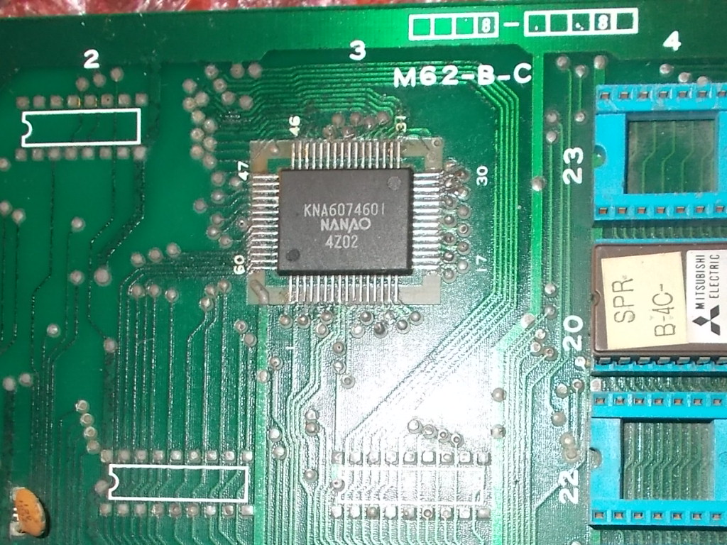
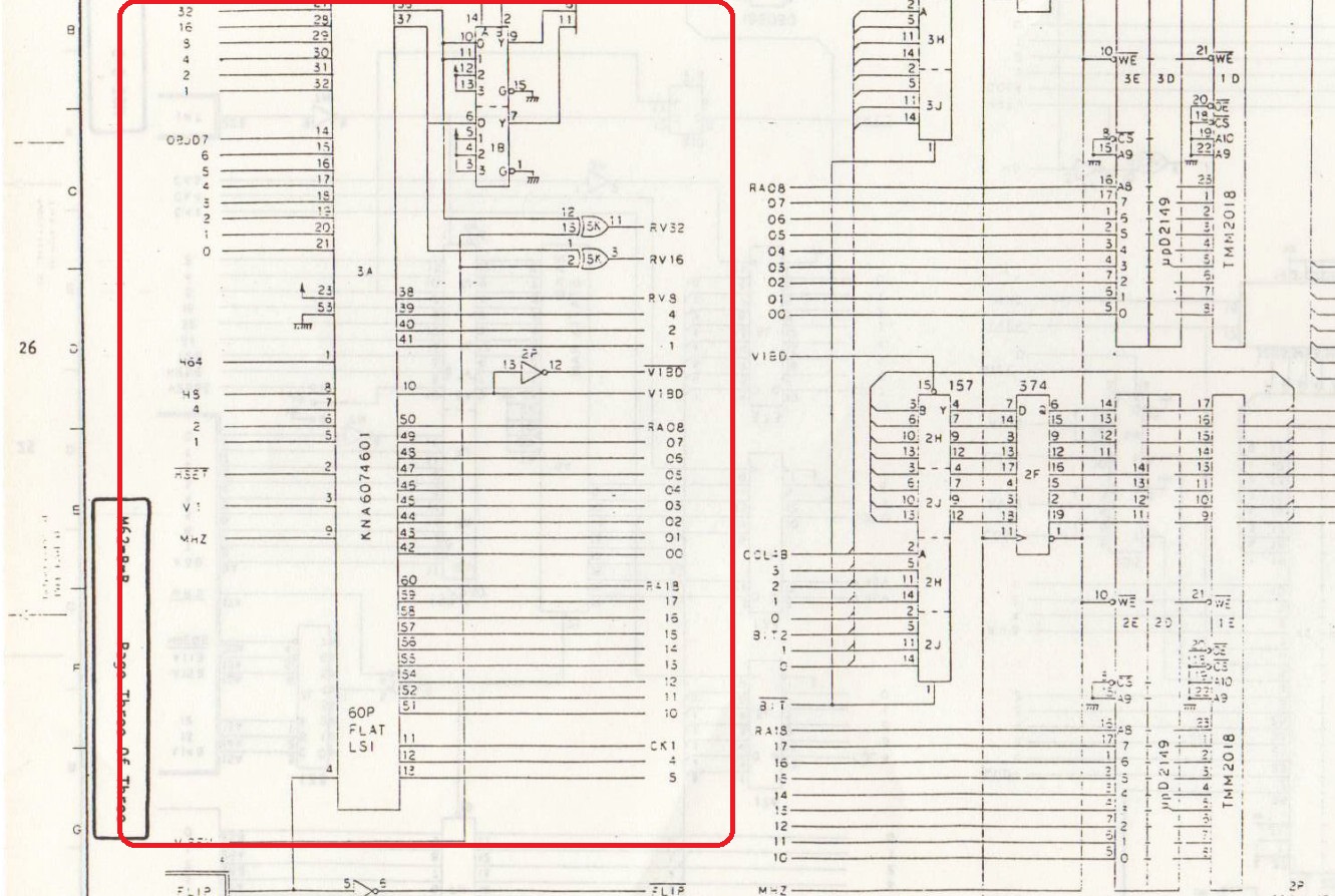
Its pinout/implementation from Kung-Fu Master schematics :
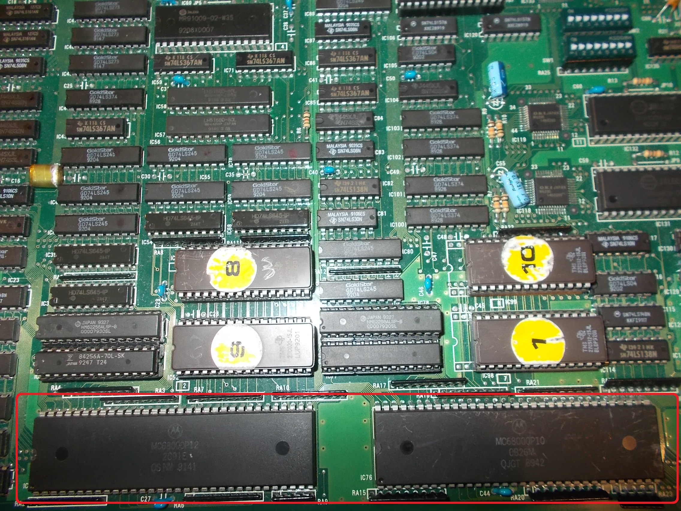
I had no other choice than replacing this part so I asked the owner to look for a donor board.He found and sent me a Vigilante PCB which carried the ‘KNA6074601’ on bottom board :
I removed the faulty one and soldered the spare back :
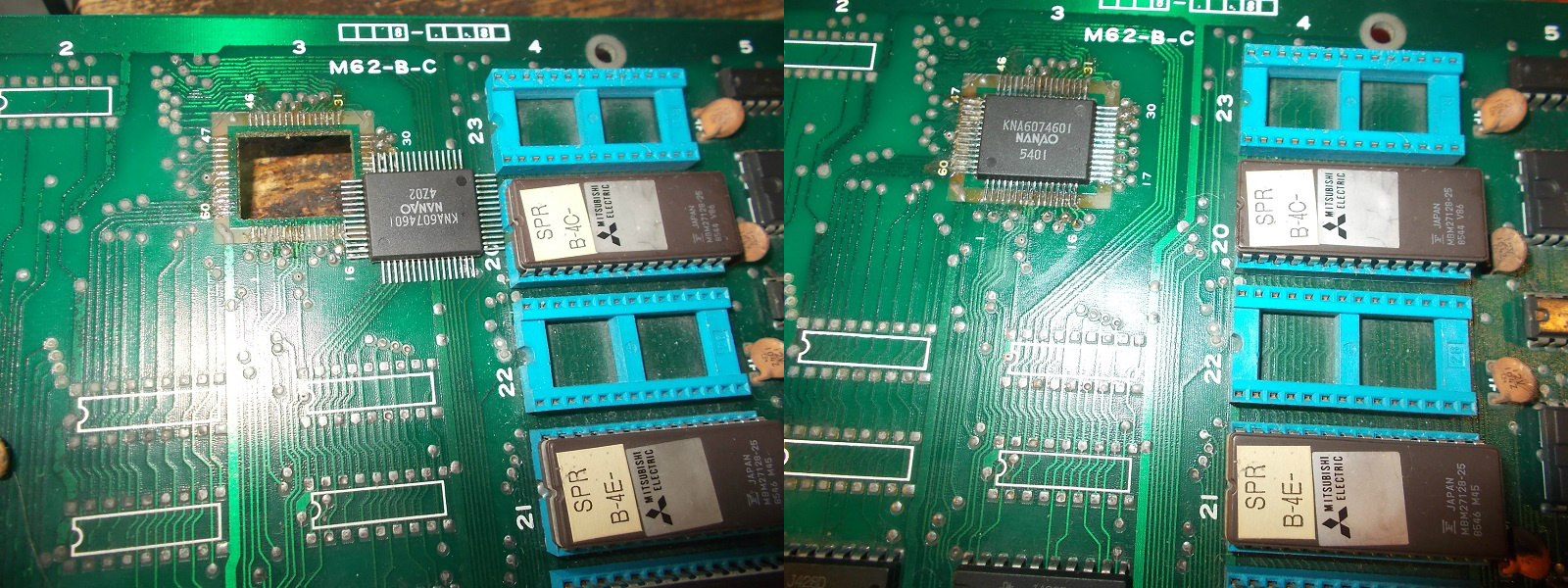
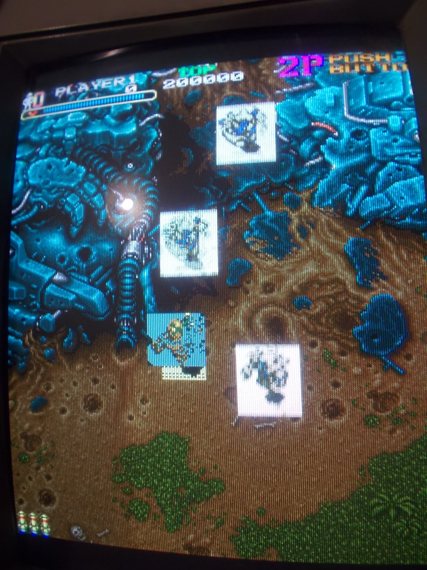
This restored the correct sprites:
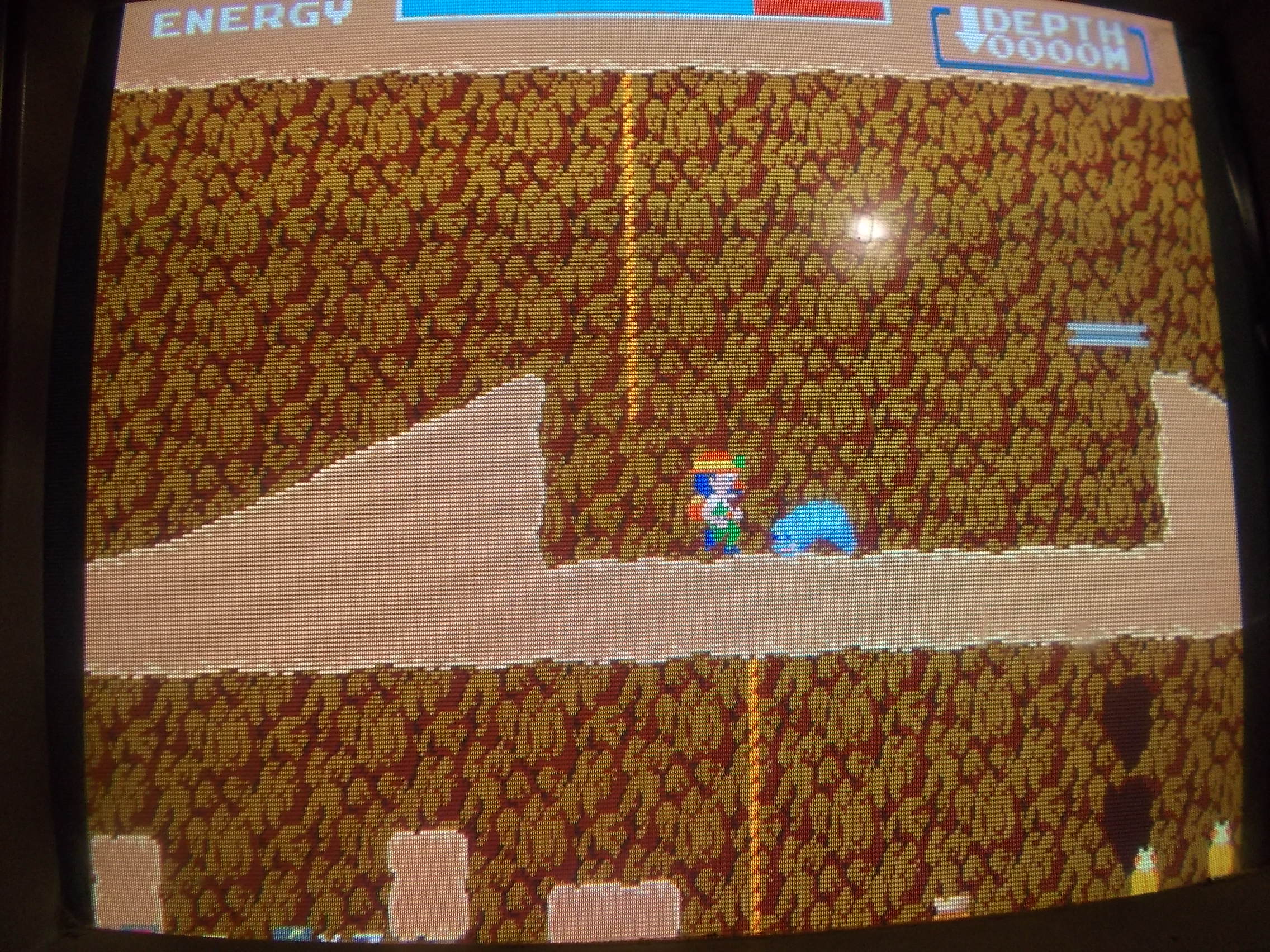
Board 100% fixed.Job done.