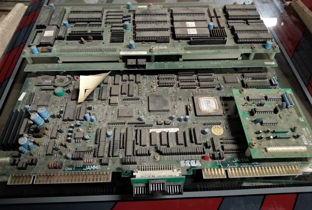
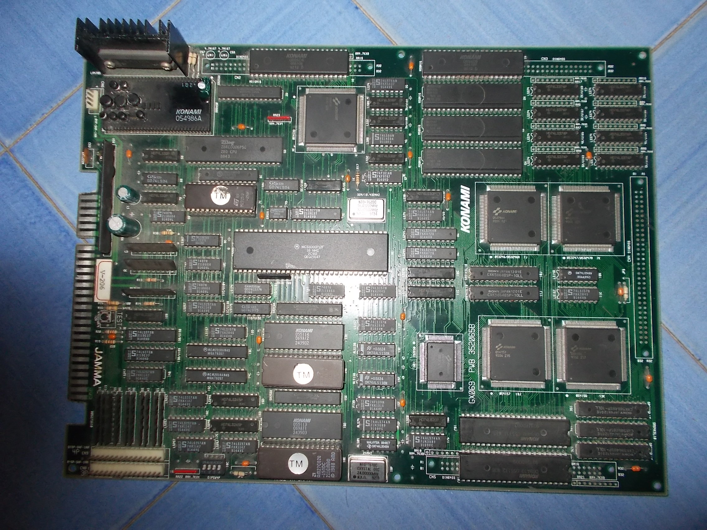
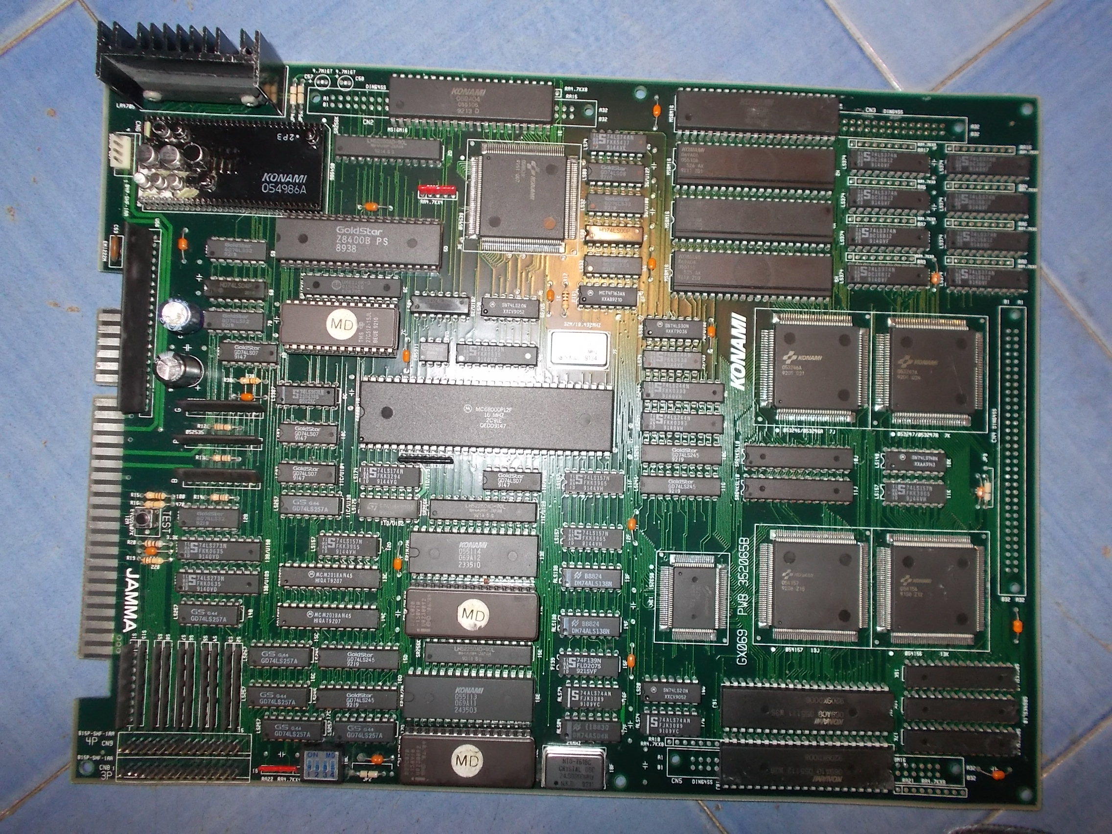
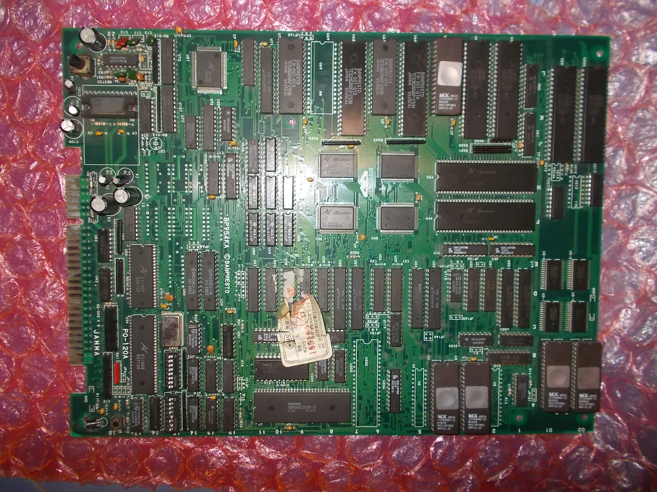
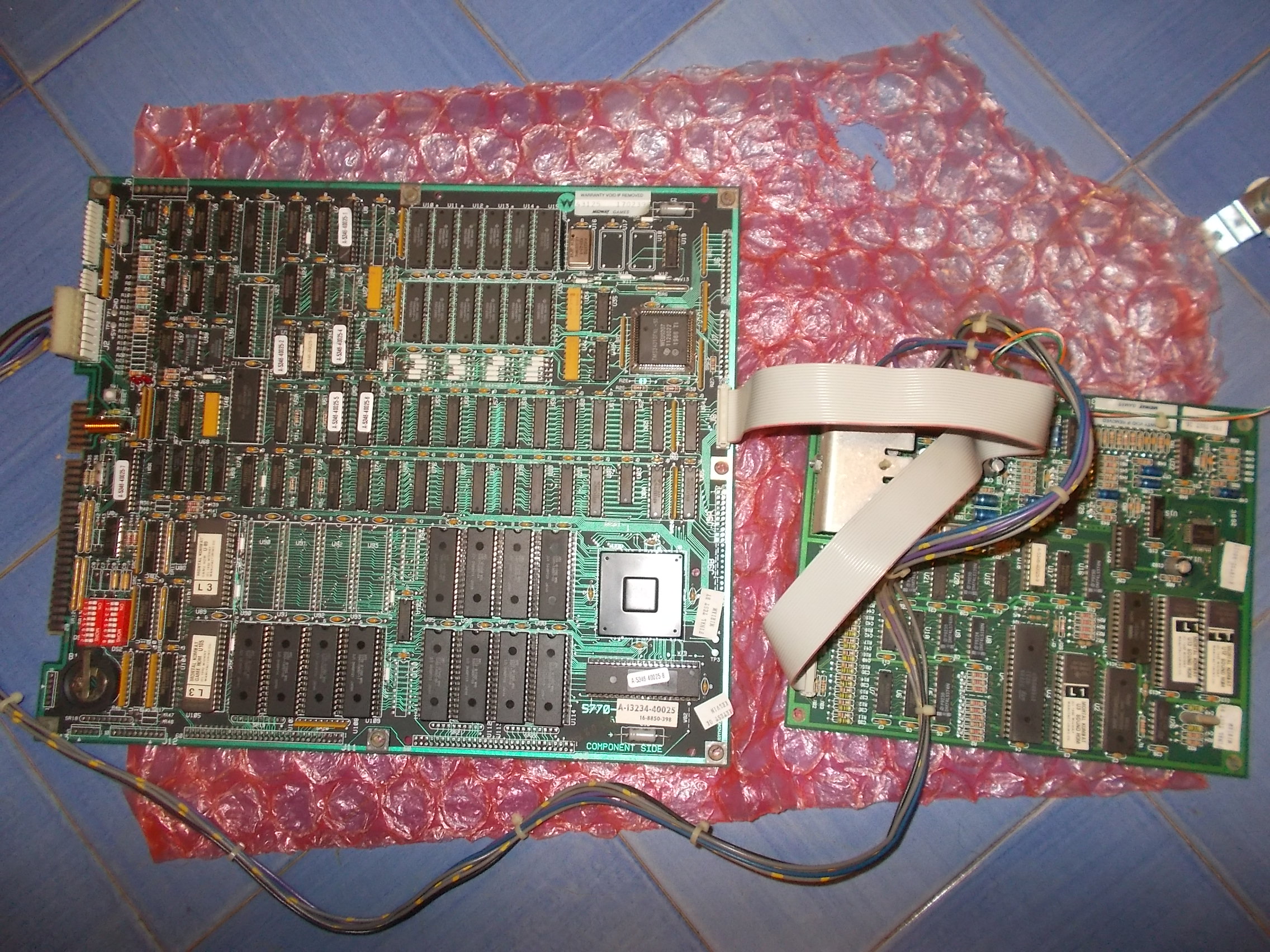
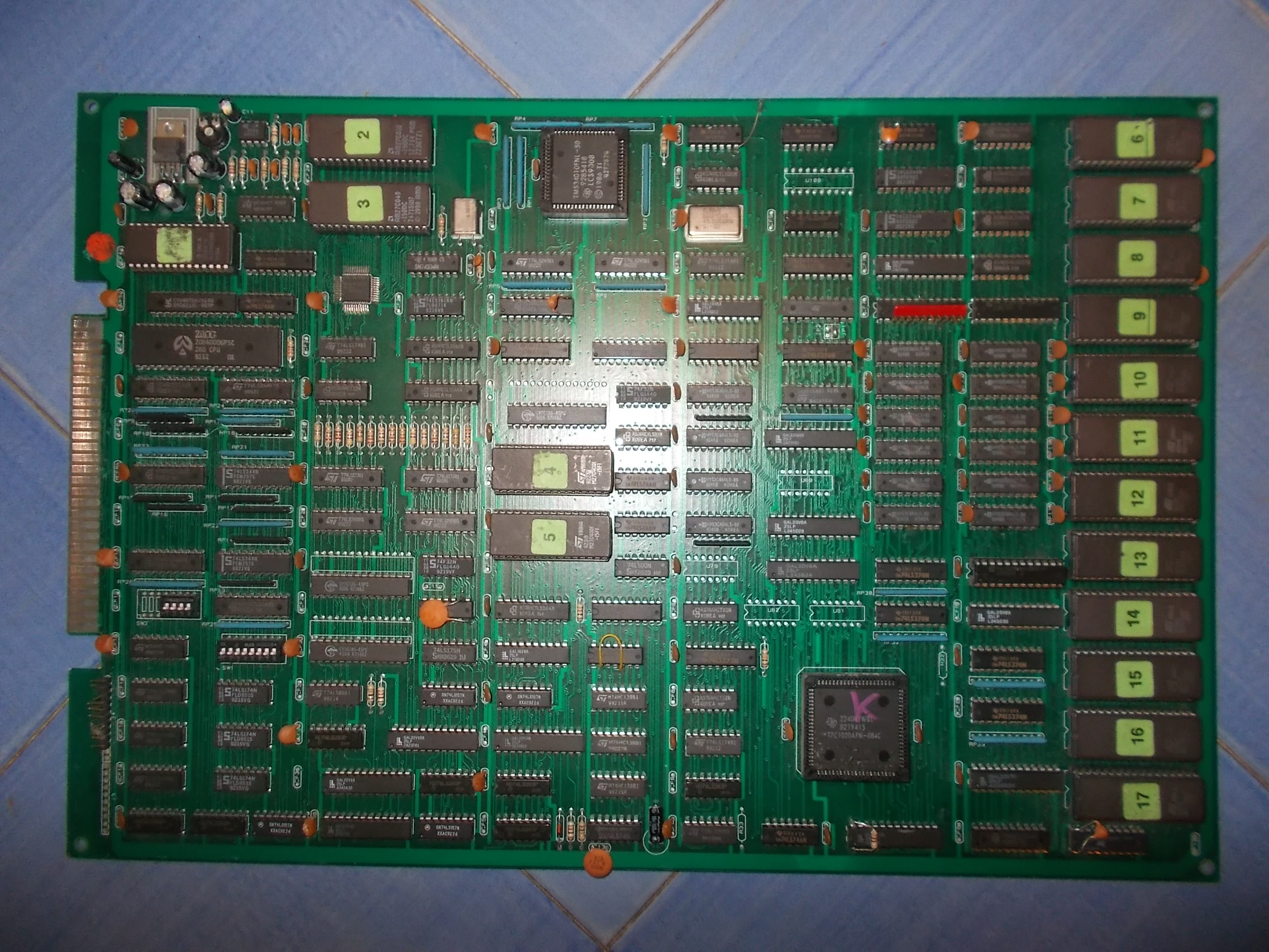
Got from USA an original Mortal Kombat PCB set complete with its sound board:
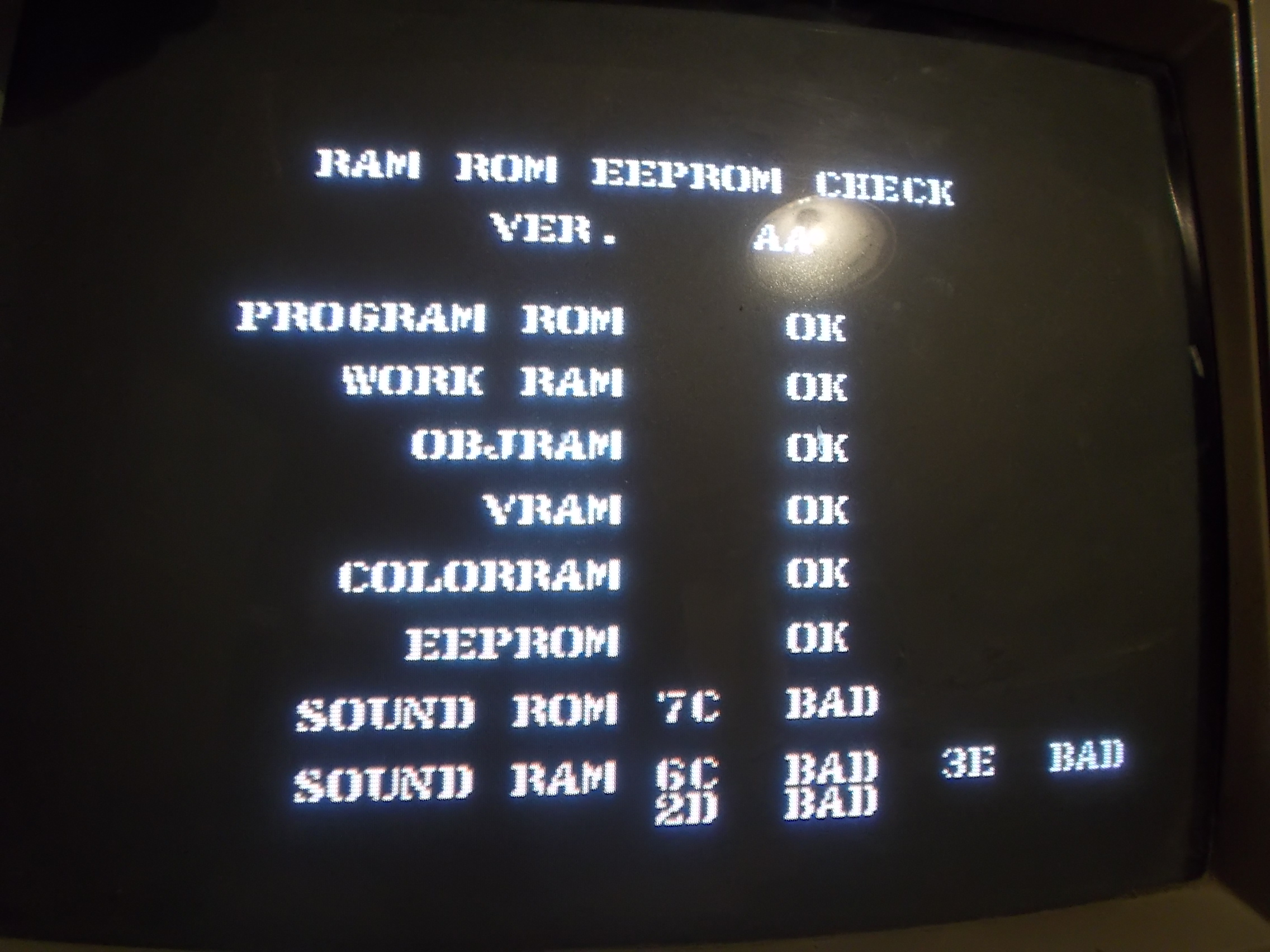
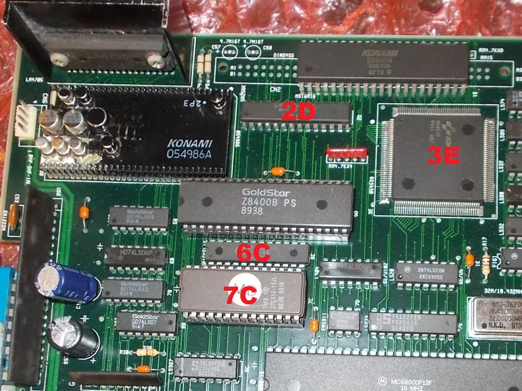
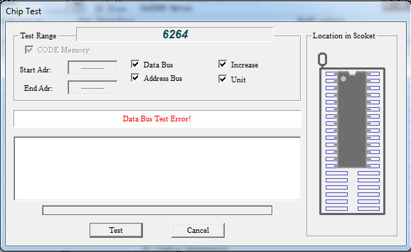
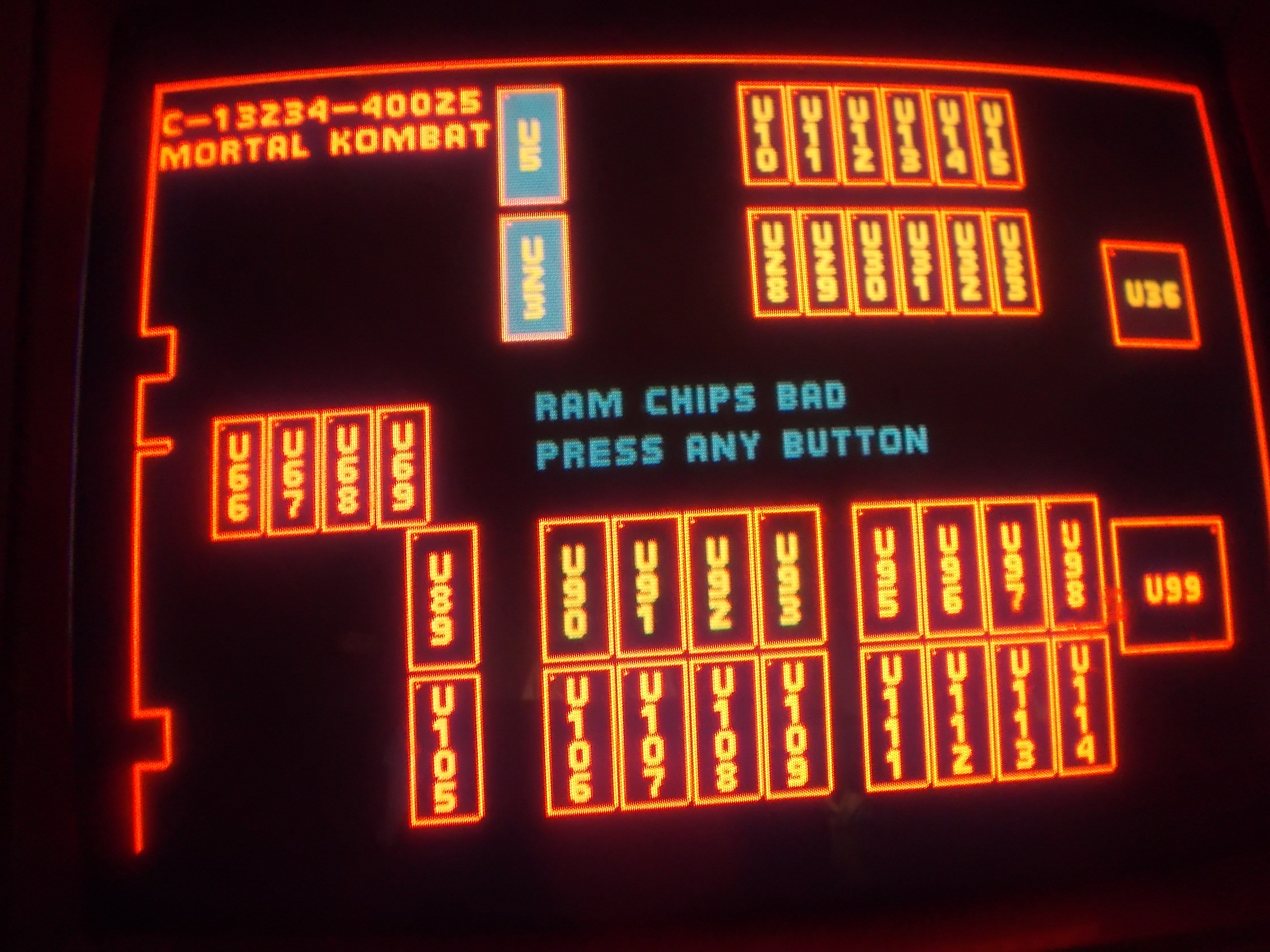
When I powered the board up the self-test reported two bad devices @U5 and U23:
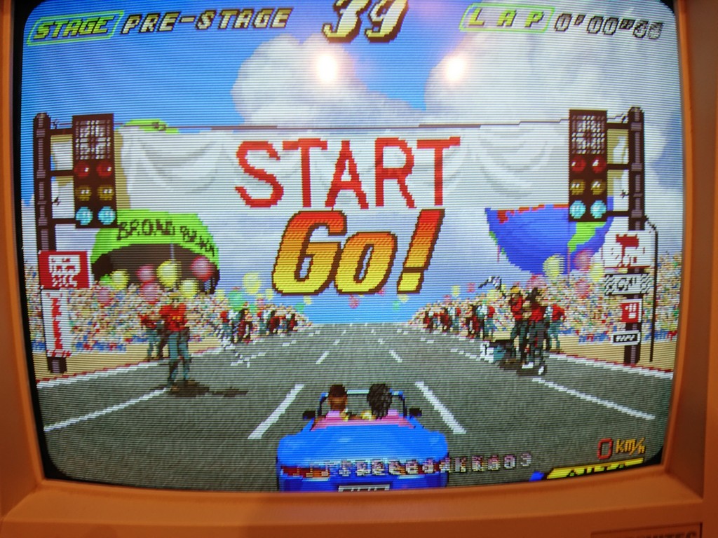
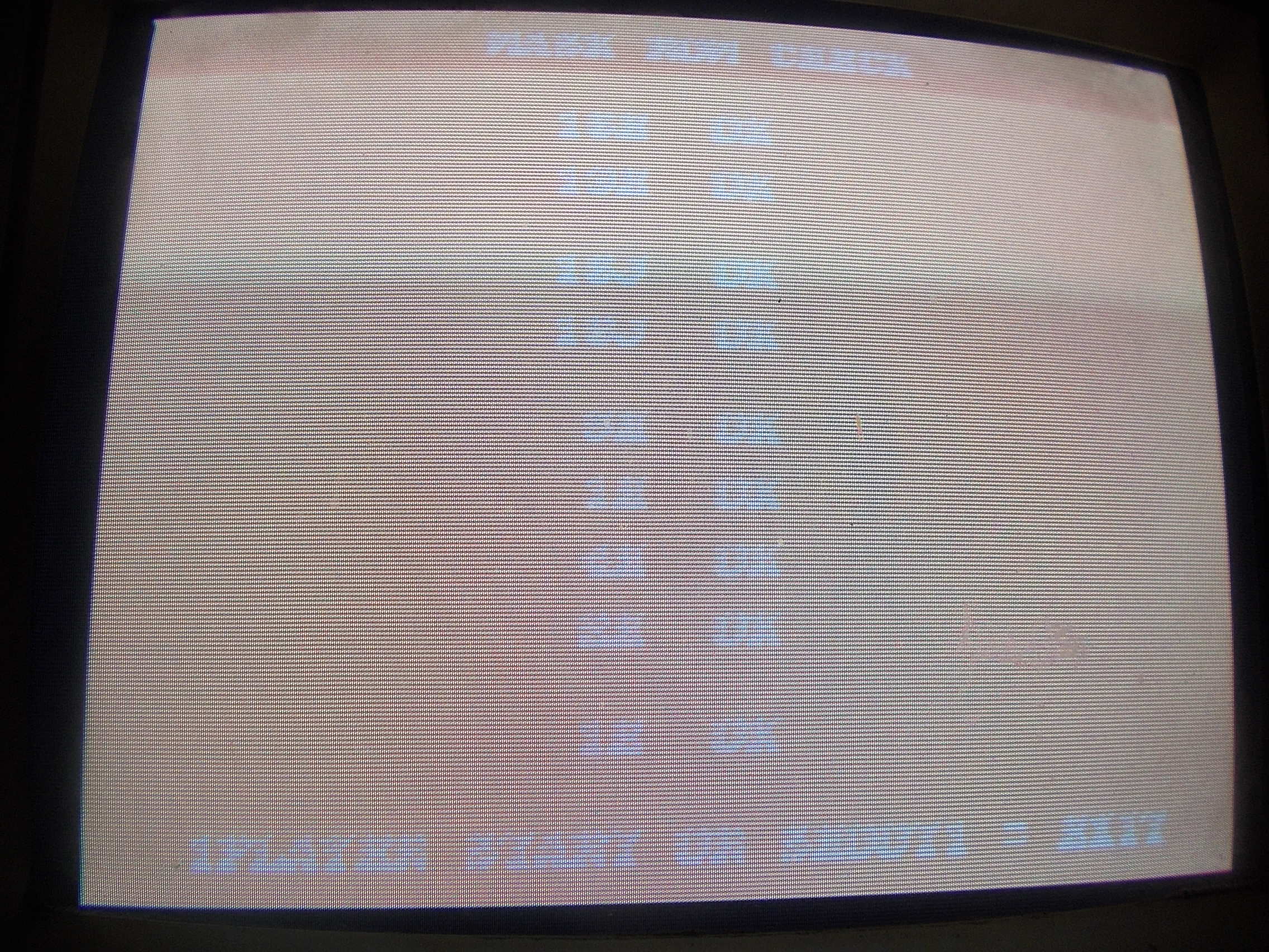
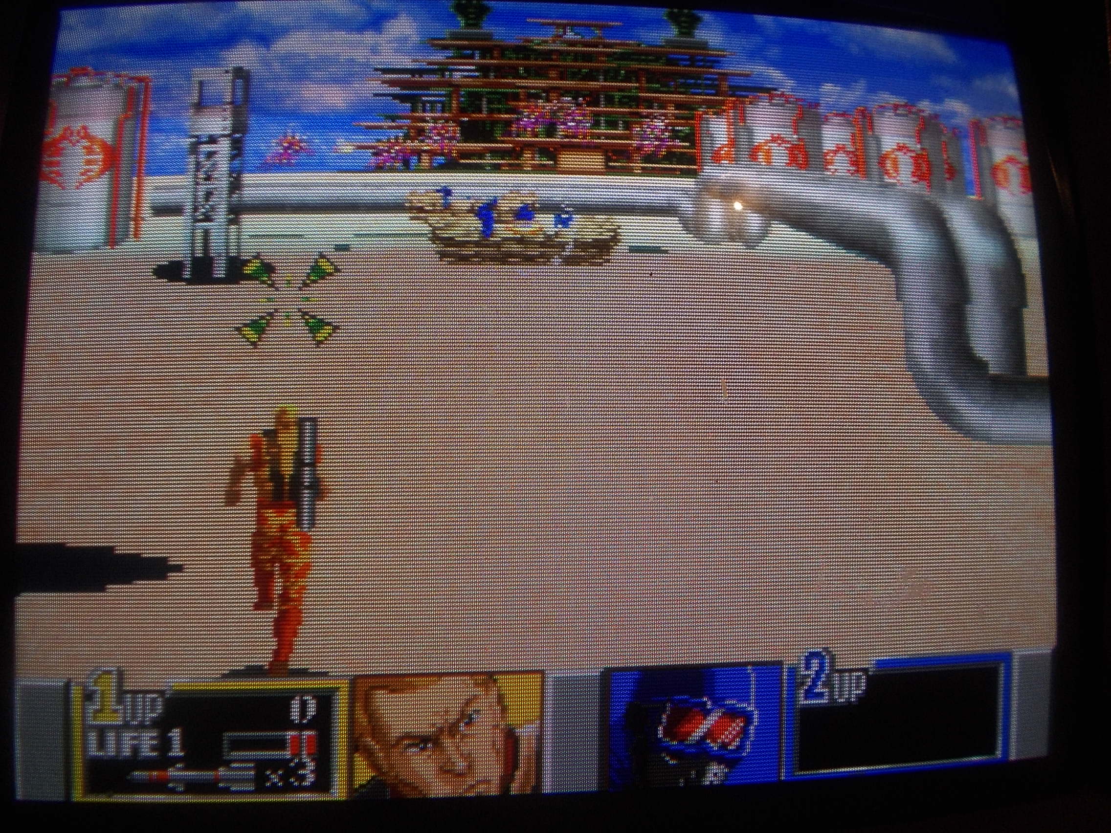
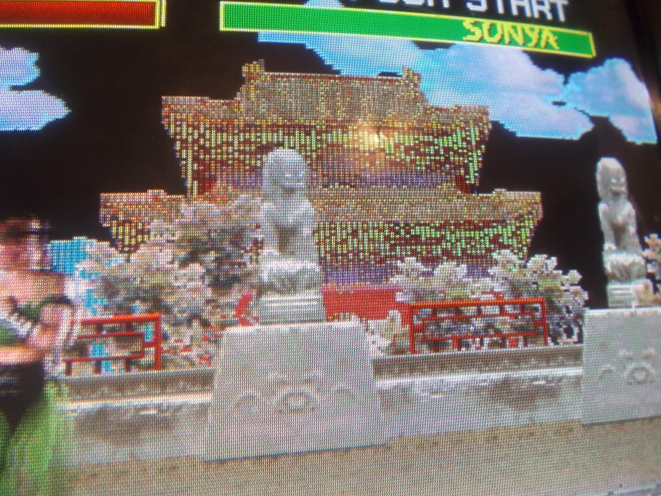
Then it booted into game but colors were completely wrong:
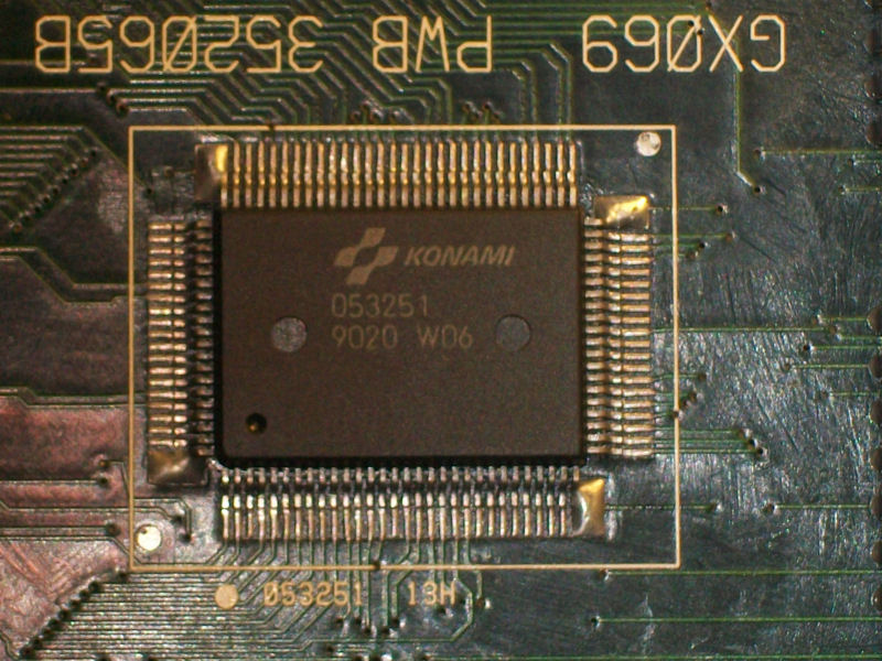
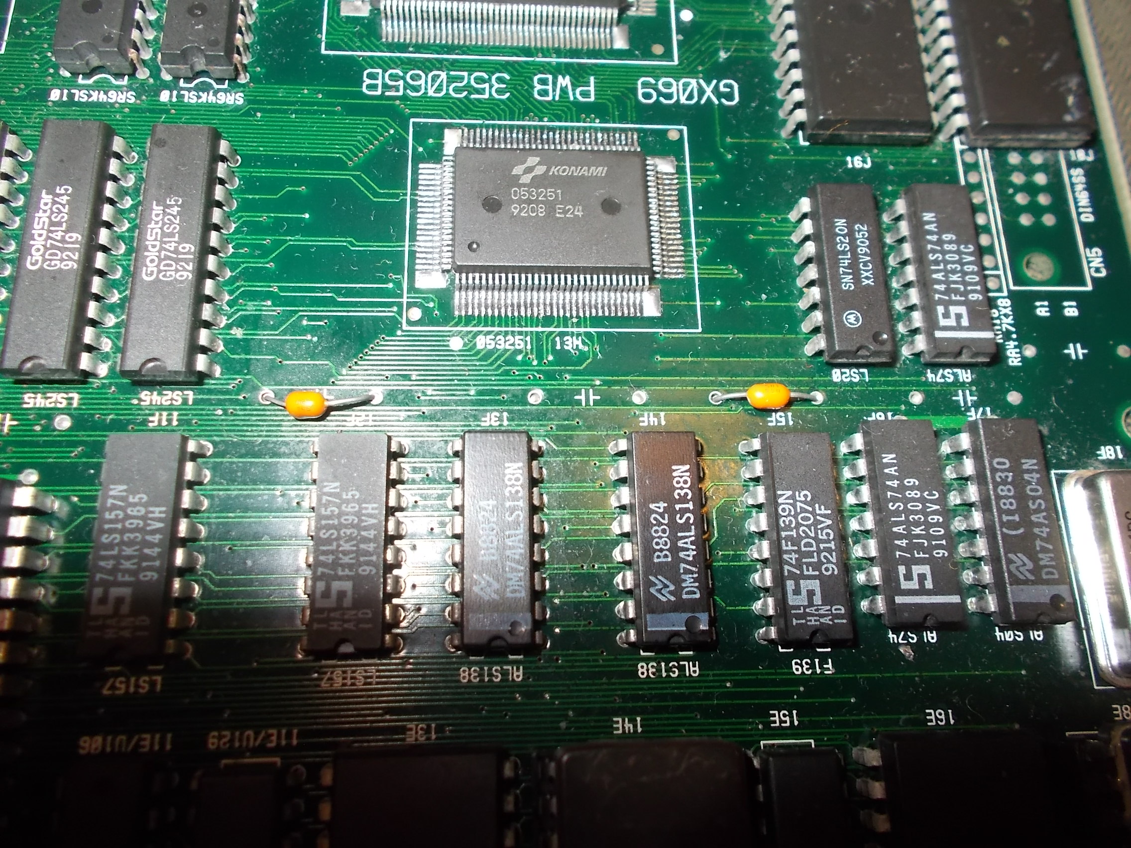
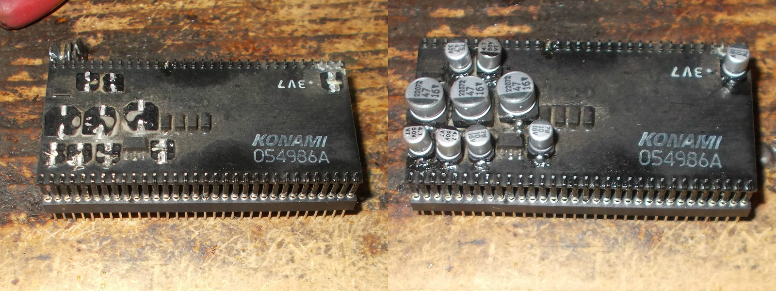
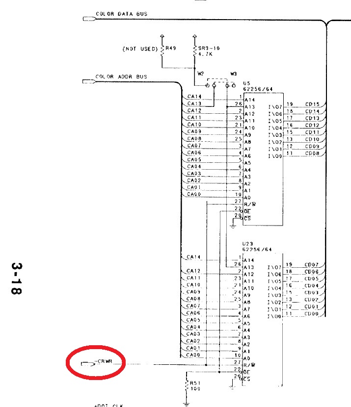
The two presumed bad devices are the color RAMs (Sony CXK5863 so 8K x 8-bit, pin-to-pin compatible with the more common 6264)
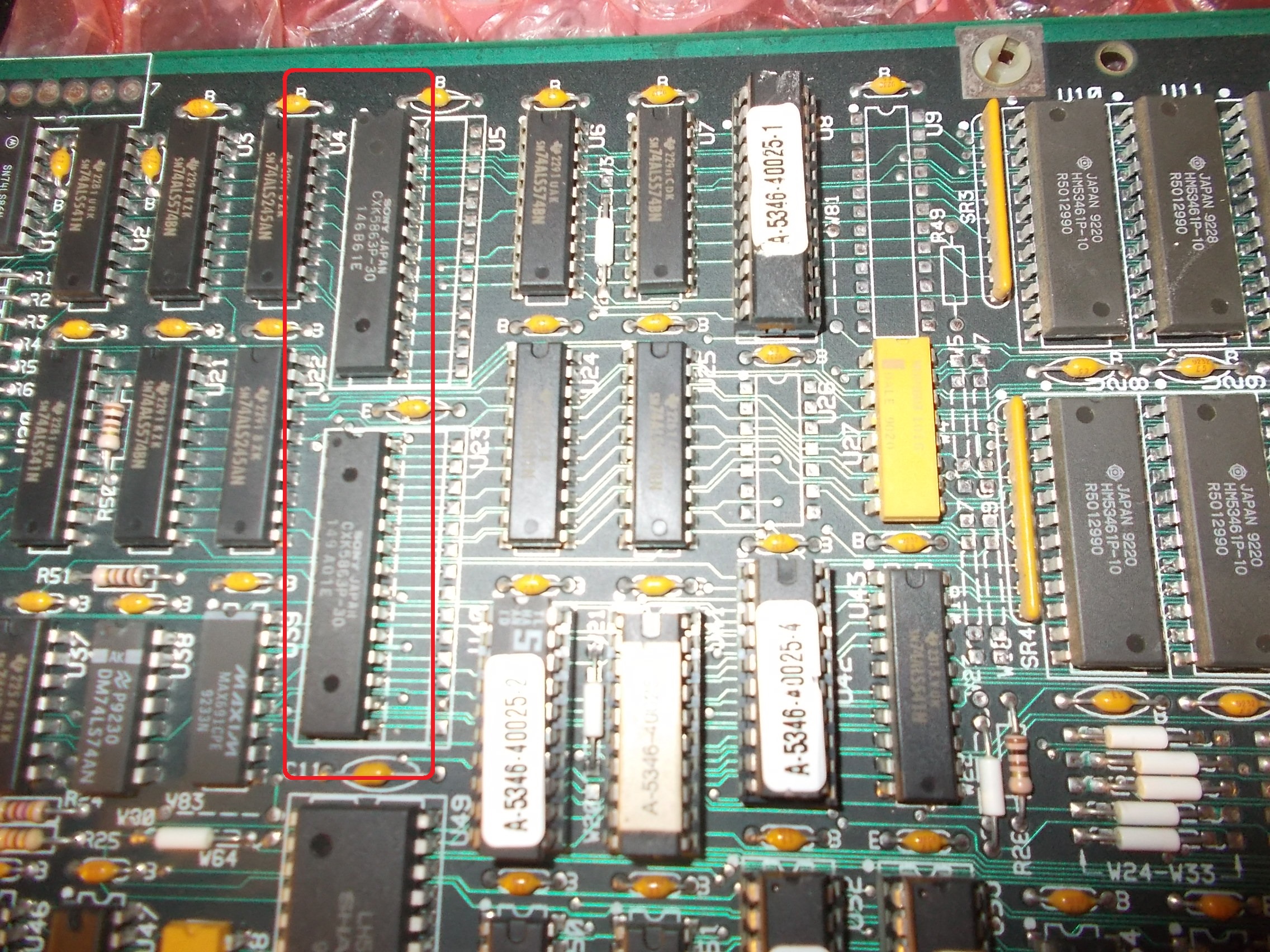
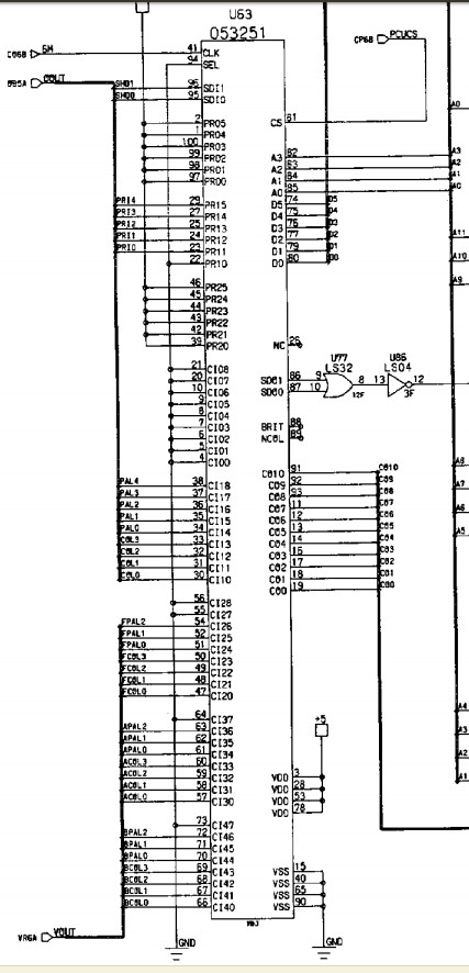
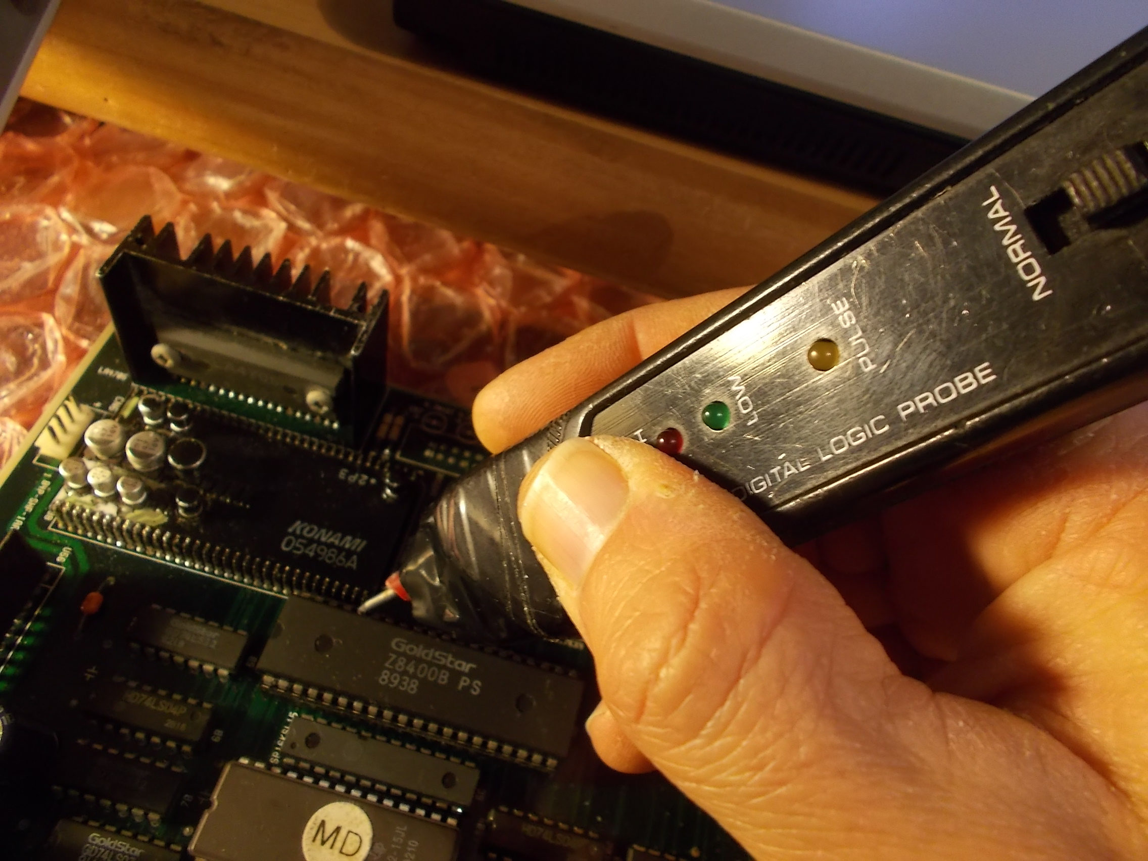
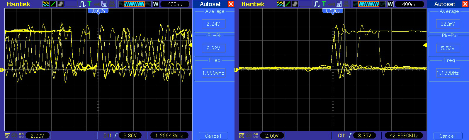
Probing them revealed that pin 27 (Read/Write enable line) of both was stuck high:
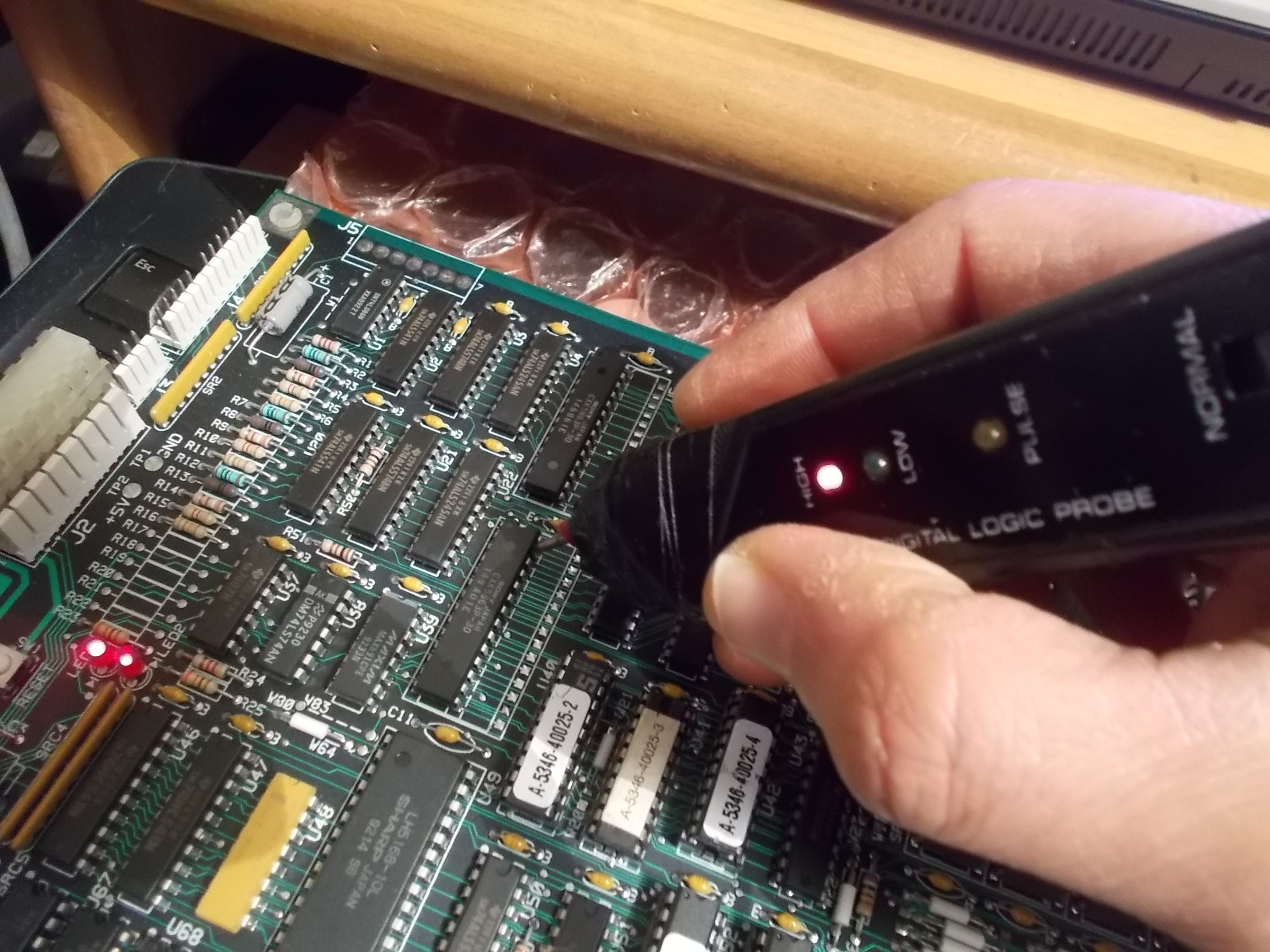
This input signal is labeled on schematics as ‘-CRWR’ :
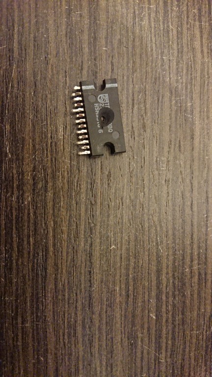
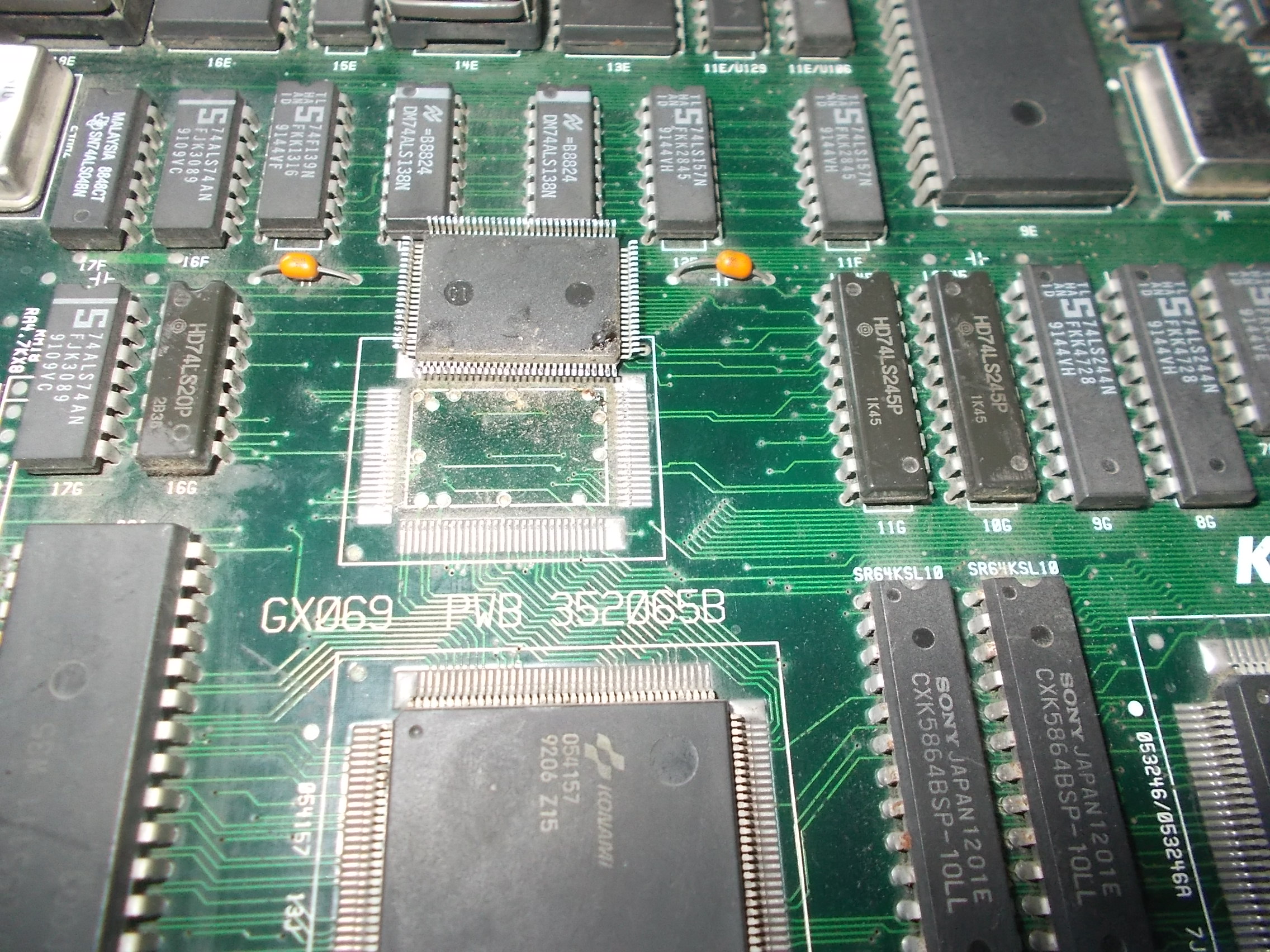
It comes from pin 22 of a 24 pin IC @U8:
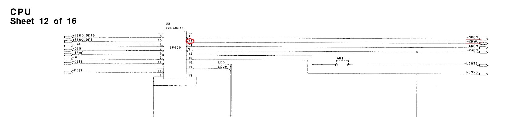
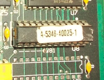
The IC was faulty and needed to be replaced.At first glance I thought it was a simple PAL/GAL but actually it turned out to be an Altera E600 EPLD (so still a programmable logic device but something more complex with two clock inputs providing sequential logic too ).I had no chance to dump or reverse it but only to look for a donor board.Luckily I was sent another original Mortal Kombat PCB completely dead which I took the part from.Board was then fixed :
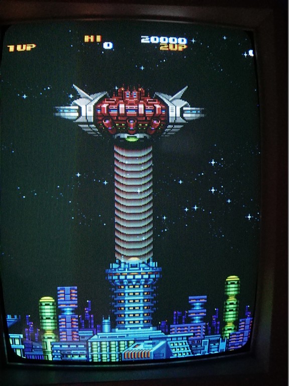
The bootleg I received for repair was the Yawdim one with no Midway logo on title screen :
It was fully playable but some backgrounds graphics were wrong :
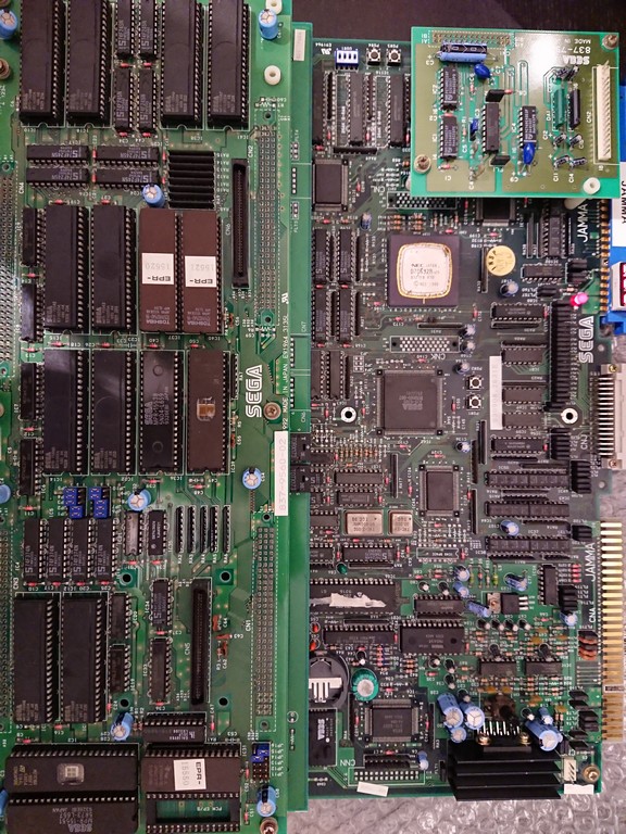
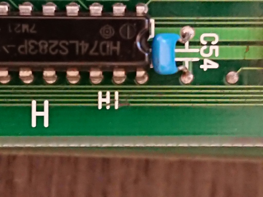
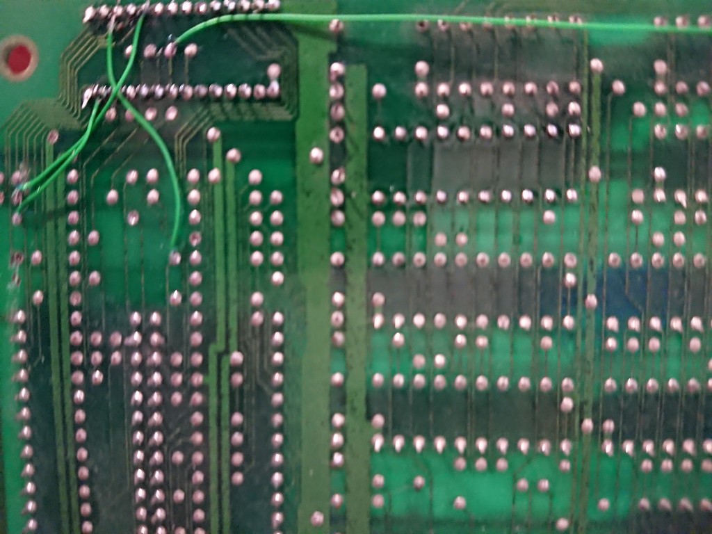
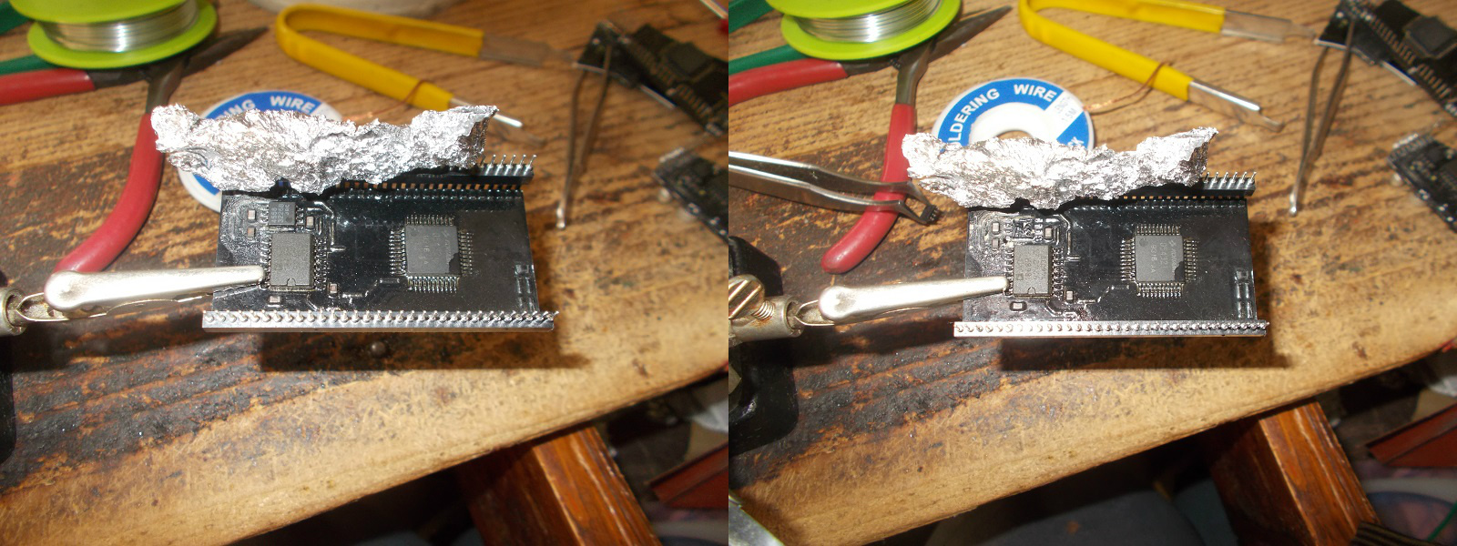
As usual I did a visual inspection of PCB and found on solder side a scratch that apparently had severed a trace:
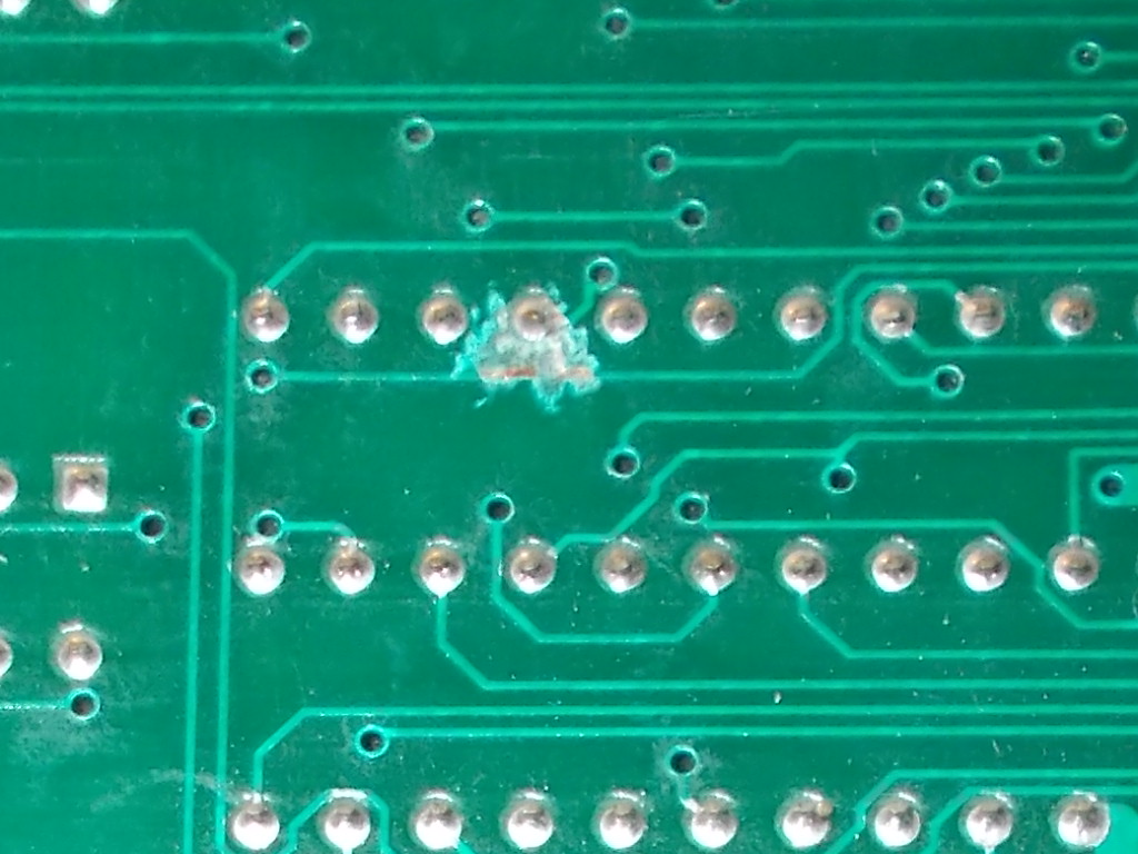
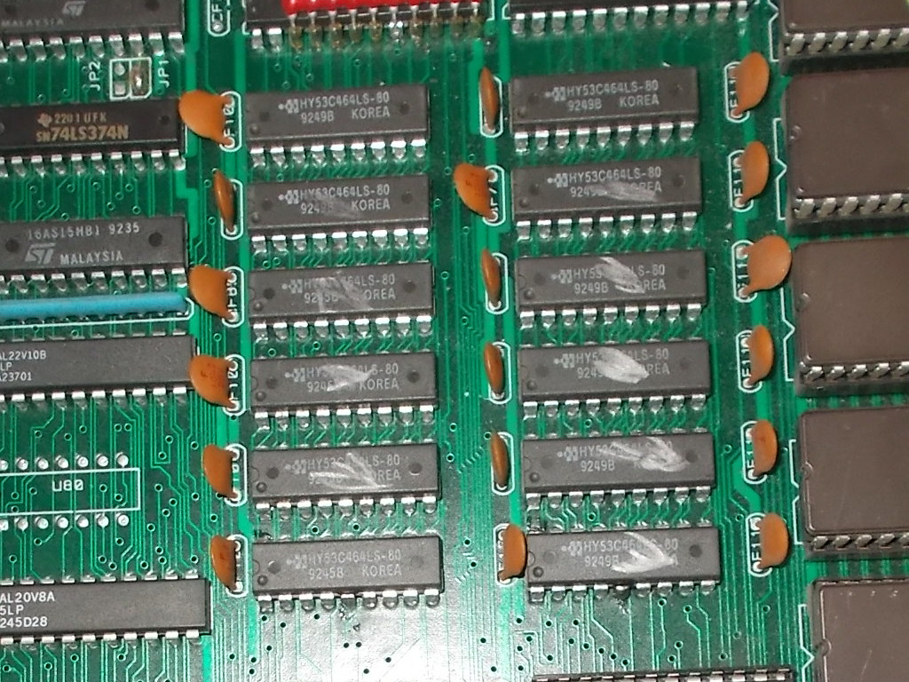
The involved area was the one populated by some 64K x 4-bit dynamic RAM so this was relevant to the kind of fault :
Checking with my multimeter confirmed the trace was really broken so I patched it, this restored background graphics and fixed the board:
Double repair accomplished.