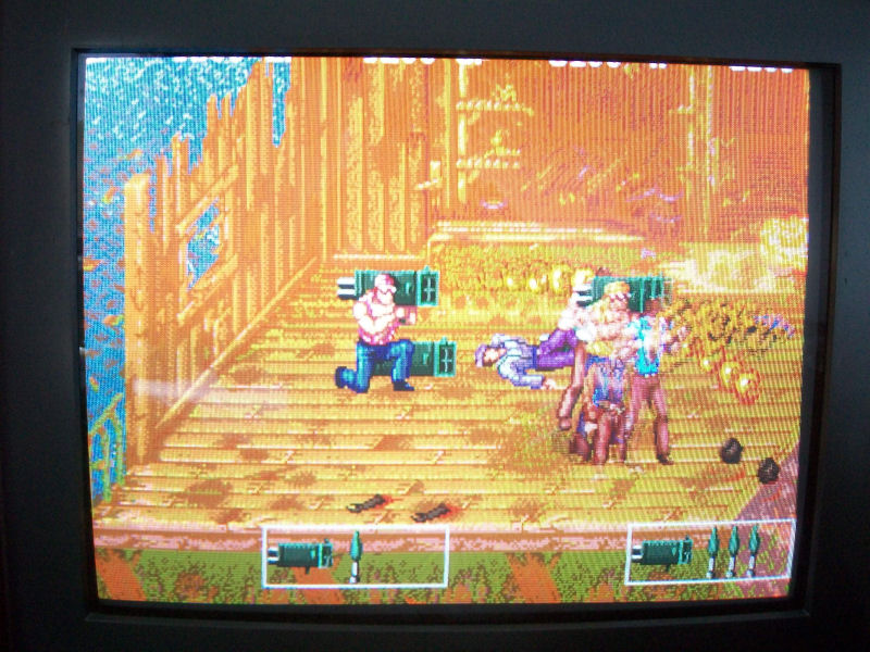
Yesterday I got a lot of faulty original PCBs.Among these there was a clean Growl PCB.I always like this game (and played it in MAME) where the player controls a forest ranger who must protect the local wildlife from a group of evil poachers who are driving the animals to extinction.
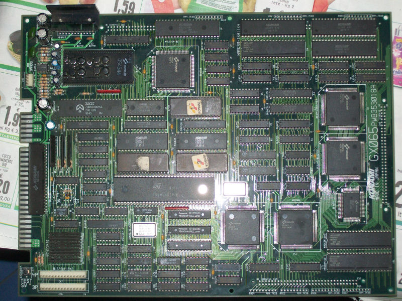
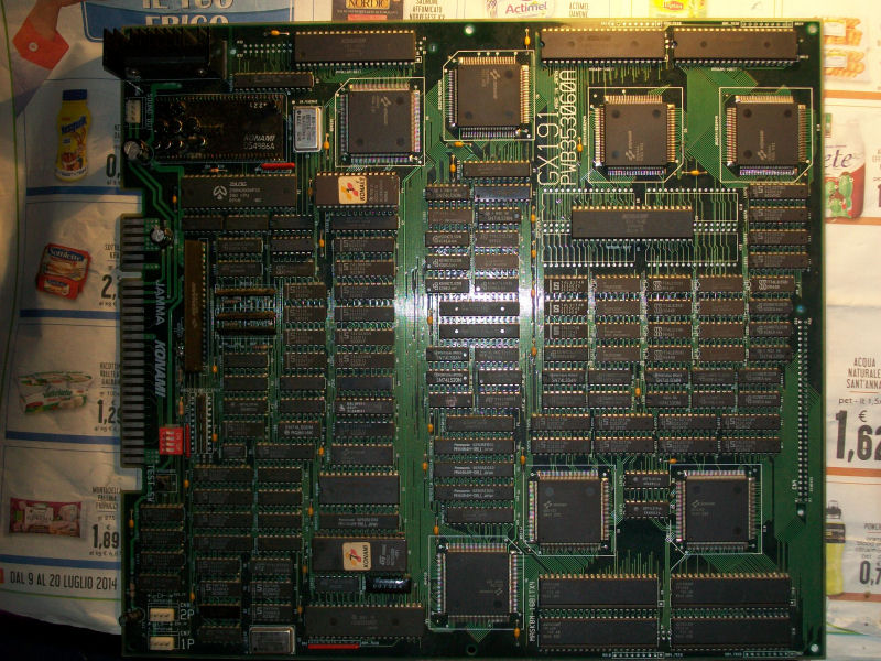
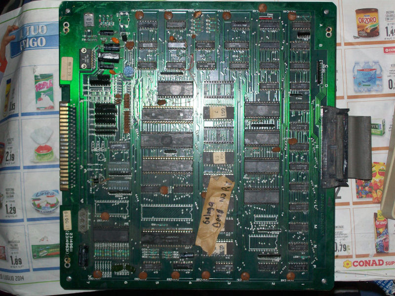
As said, PCB was in mint state:
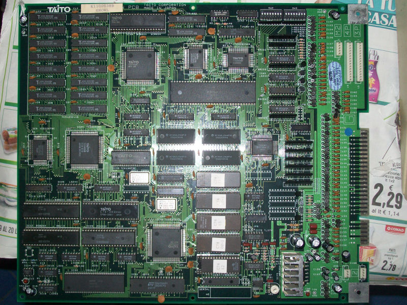
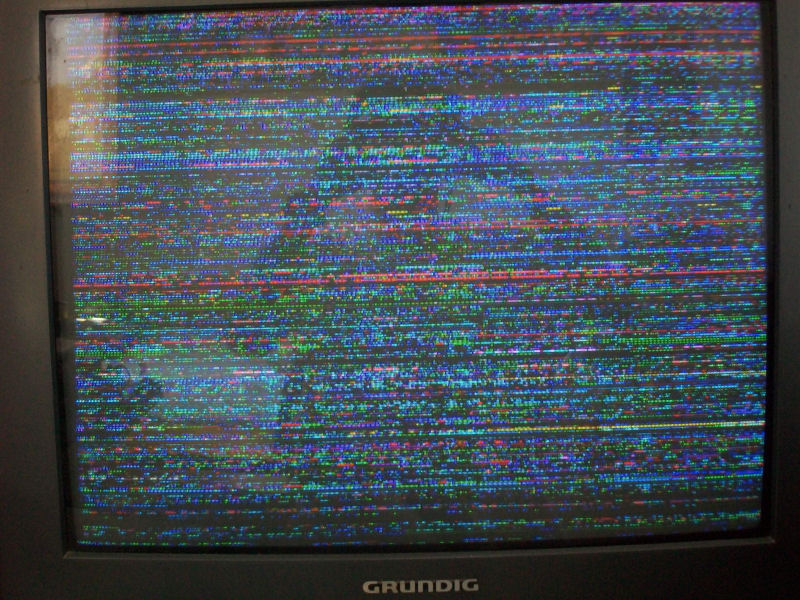
but once powered up it showed garbled sprites:
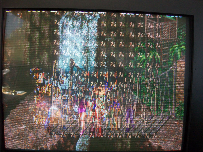
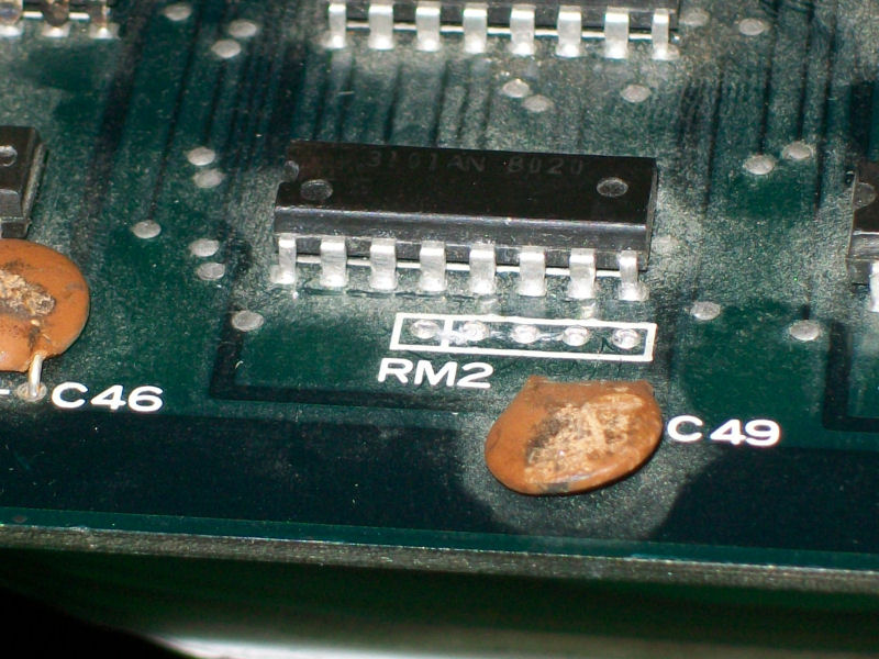
I noticed that, if I press the PCB in the area near the ASIC marked ‘TC0540OBN’ @IC25, all the sprites were restored.
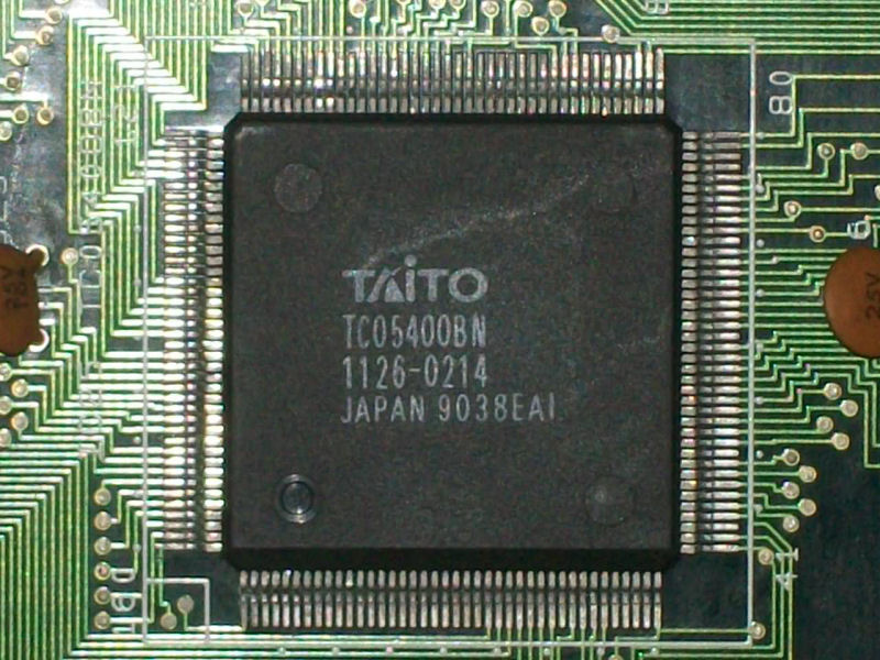
So ,after a quick consultation of MAME source that confirmed this ASIC as a sprites generator ( the letters ‘OB’ in the ASIC name stand for objects a.k.a. sprites), I understood this was the way to follow in my repair.Probing the tightness of the individual pins with a needle I found some lifted ones.A reflow with my hot air station at 390° and a bit of flux was enough to fix the sprites issue completely.