Got a mammoth box of boards from Ben76 the other day. This Star Jacker PCB is one of them.
Game gave a black screen when powered up and there was no sync signal.
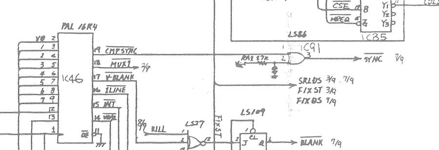
Ben also gave me a scan of the schematics for this board so was quickly able to determine where the sync came from.
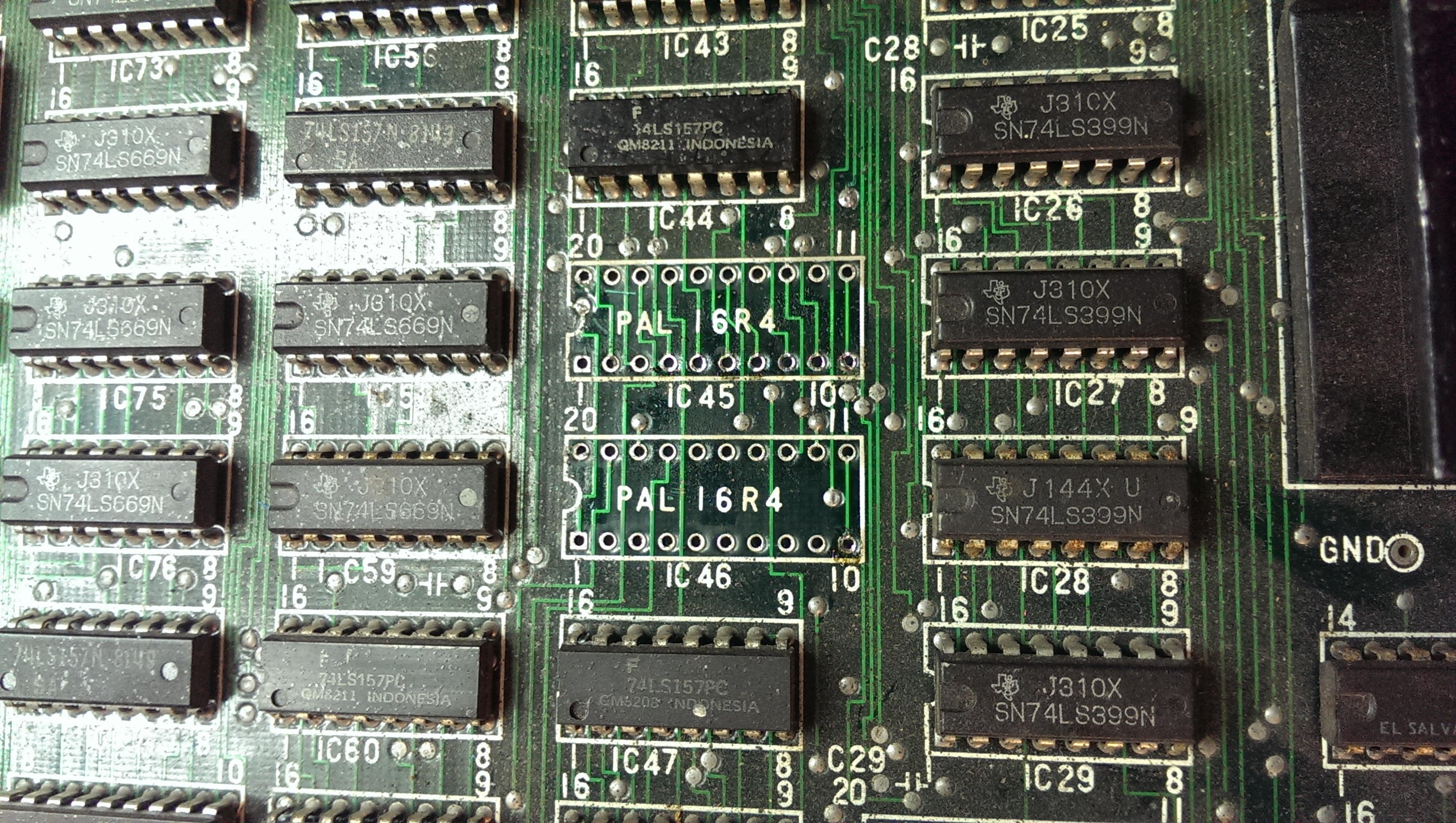
My heart sank a little bit as the sync comes from a PAL16R4 chip

On investigating I found the VCC pin was not making a good contact in the socket so I removed both of the PAL sockets and replaced them.

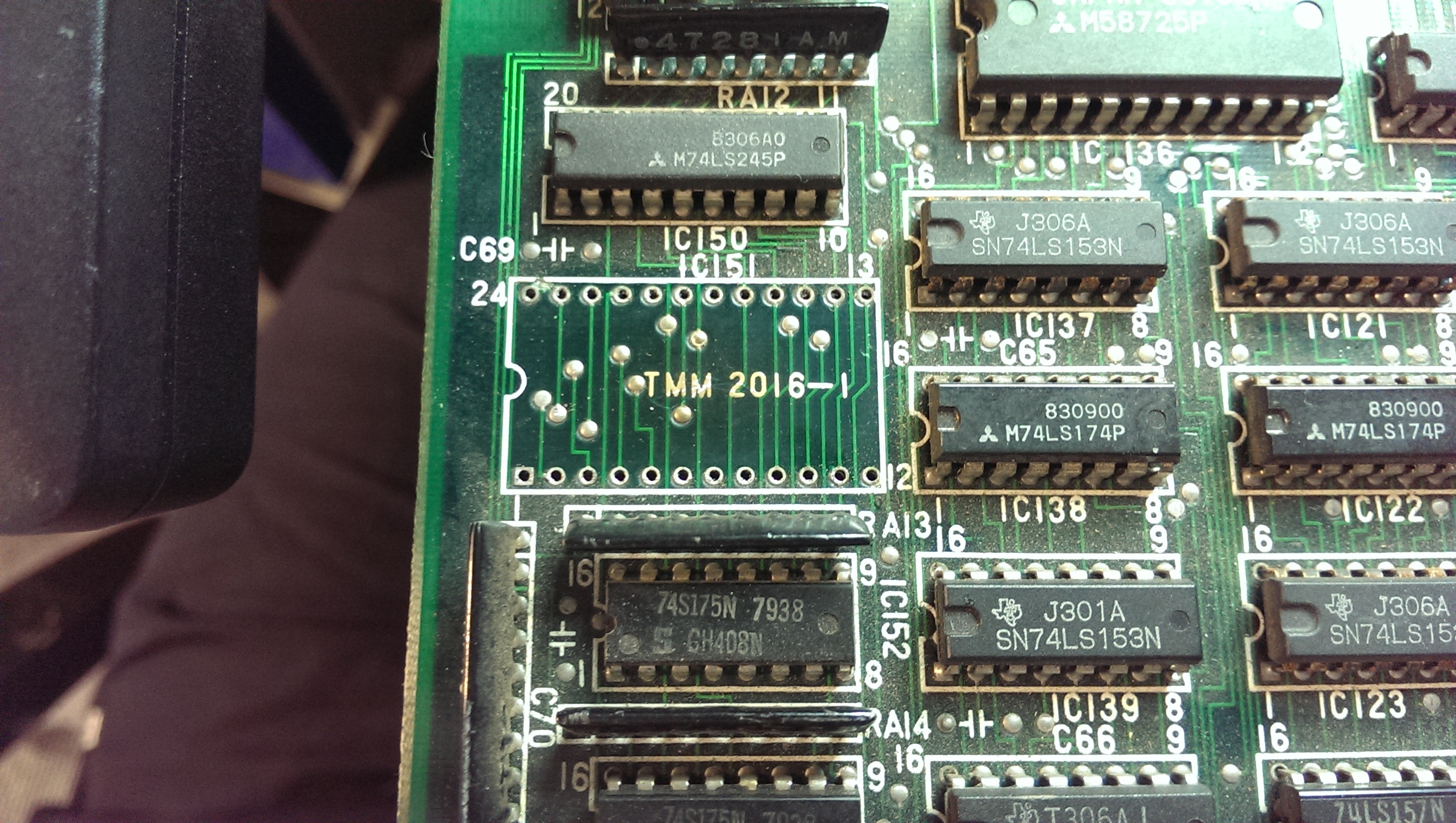
So booting now gave me sync but solid white screen. Ive seen this before on quite a few boards and its almost been RAM issues. I started probing the RAM chips and found a 2016 SRAM at location IC151 had completely dead outputs despite being enabled and having active inputs. I desoldered it and replaced it with a 6116 SRAM chip.
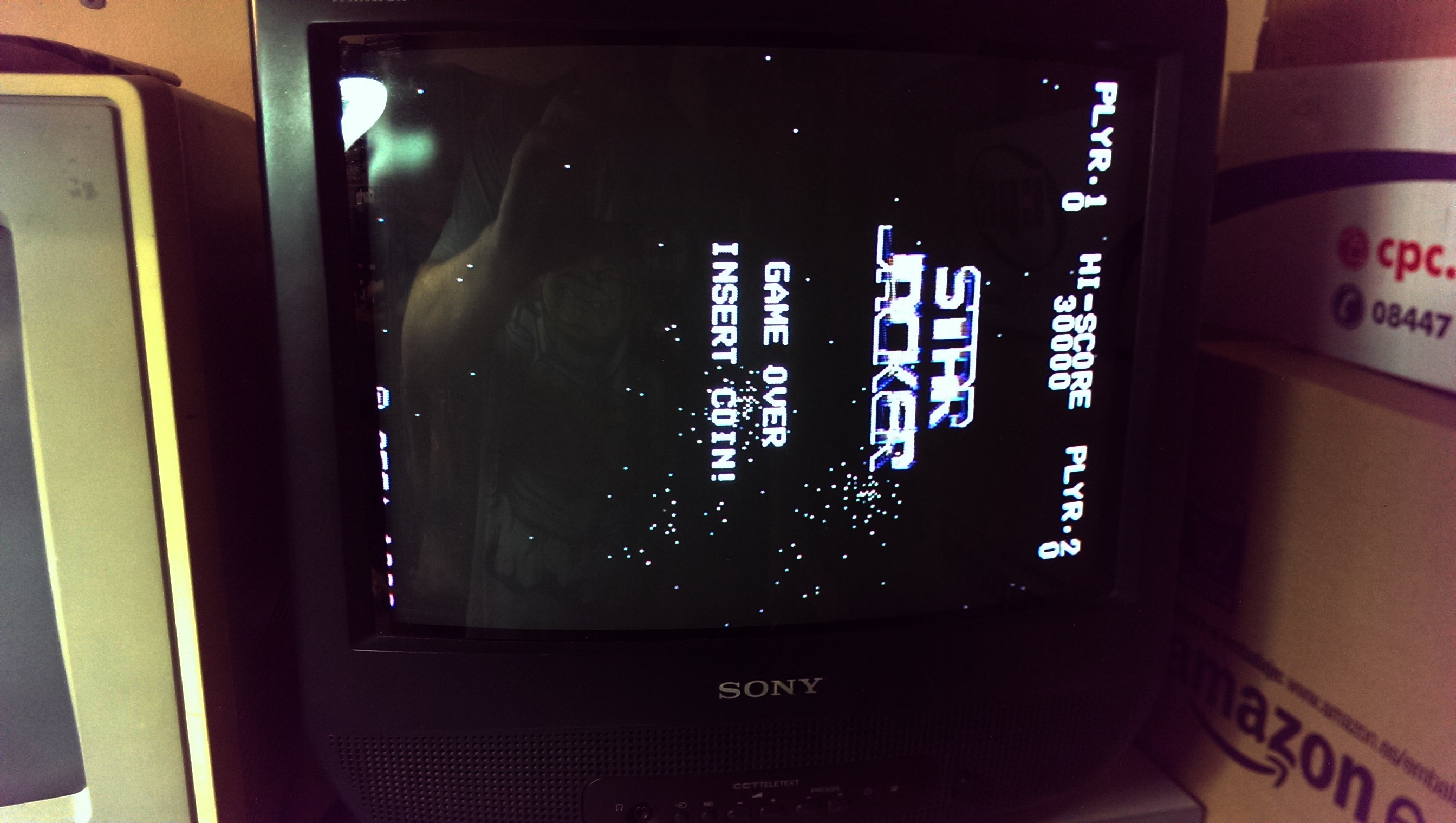
Now I get this (NOTE: the red colour is actually present but I have to edit my pictures these days as the HTC One makes low light pictures all purple)
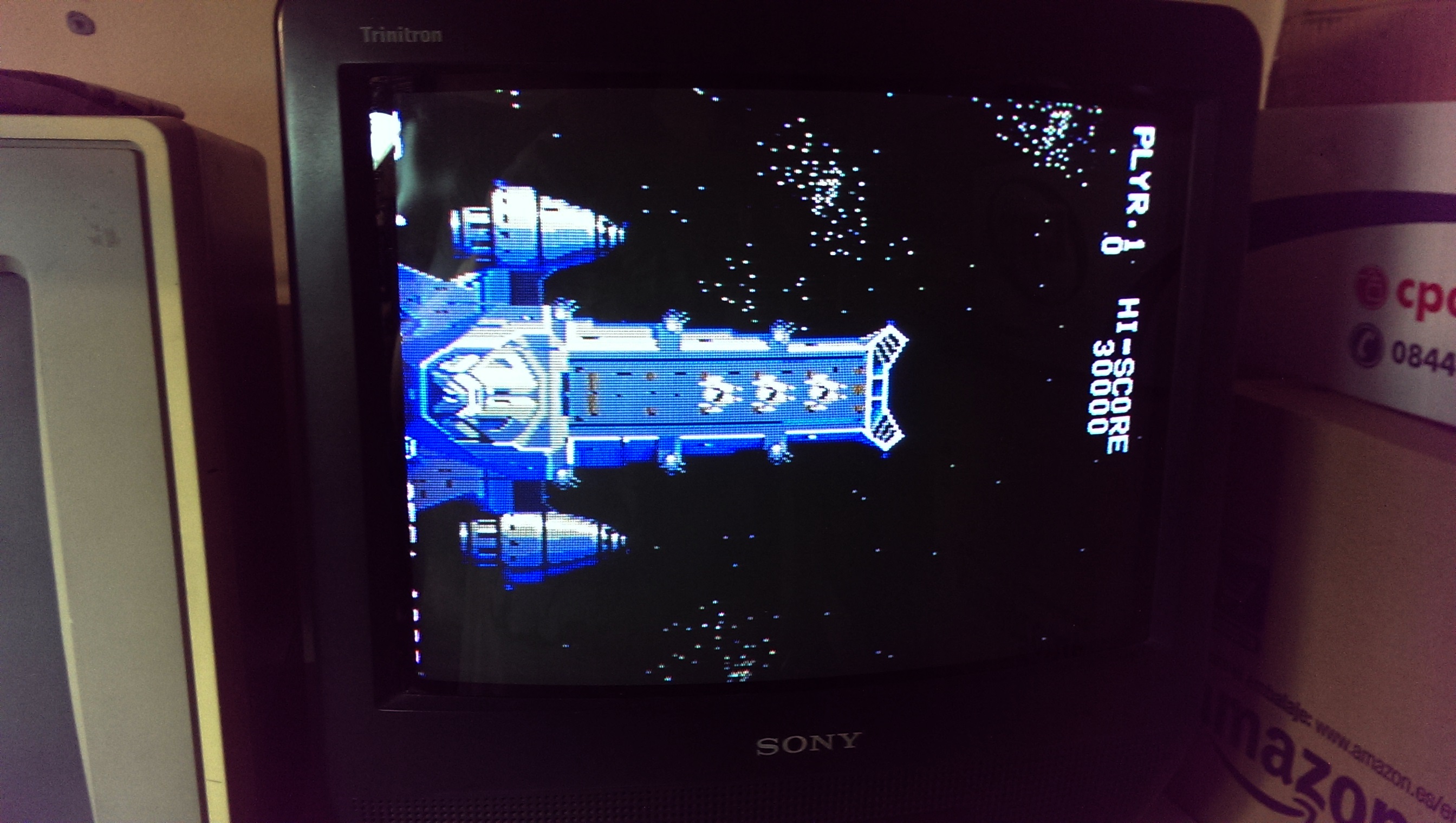
All fully working again.